#Adjusting CAD Drawing Size
Explore tagged Tumblr posts
Visit Tumblr Blog
Explore Tumblr blogs with no restrictions, modern design and the best experience.
Last Seen Tumblr Blogs


Fun Fact
12.7% of mobile users access Tumblr.
Text


FIRST TIME DOING COMMISSIONS WOOOO. I really wanted to open comms but I'm also busy with uni so for compromise, I'm just keeping it to simple, monochrome sketches for now! ko-fi here!
Detailed info + link to info document under cut
Commission document
FINALLY sketch commissions for $15 CAD.
- Any additional characters (more than 1) are $5 each added onto the original price, e.g. three characters would be $25 total.
- Headshots, busts, half-body, and full-body sizes are all $15 to keep it simple, I'll try to adjust by adding more detail the smaller the scale goes. Just let me know roughly which size you'd like 👍
✅ yea category (things I can/am comfortable with drawing):
OCs
ship/self-ship art
suggestive (not of underage characters)
light nudity and light gore
blood
anthro/furries and animals
simple props or foreground objects
❌ nah category (things I won't/am not comfortable with drawing):
nsfw/fetish
heavy gore
mech and detailed armor
backgrounds
very complex designs (think of genshin and monster hunter as the standard of complex designs)
- Always ask questions if you're unsure about stuff (like whether something is simple enough) and I'm open to discussing those details. Some things I might reject cuz of time or how experienced I am (like I said I could do anthro/animals but if I'm gonna be real, not sure if I can do insects and fish and the like justice). But it is just basic comms and sketches so nothing too wild so I'm willing to hear out anything
- Do NOT put my stuff in ai or give me anything related to ai/nft, I will EXPLODE your MIND
- Pay upfront 🙏, it's ko-fi so not like it matters but yeah
- Payments will be thru ko-fi, but if necessary, I also have paypal. Also this shouldnt be necessary but dont share my personal info (email, name, phone, etc), we do the "I do not see it" type of interaction.
- I can't guarantee how long it'll take given I gotta lock in on university, but it SHOULD be under three weeks max, and I'll try to give updates whenever.
- I'll also try to send progress sketches for you to examine and critique as you'd like! I'm forgetful as fuck so never be afraid of asking me for updates because my brain sure doesnt <3
- Also also I might ask if I'm allowed to post your comm as art (with a watermark saying it is a commission), and you're free to say yes or no.
- Most of all: this is my first time really doing this stuff so have mercy 🙏🙏🙏 especially with the payments and remembering stuff.
Ok DMs are open and you can ask me there YAYY
Other extra things:
sending me references is COOL and GOOD!
I am fine with you giving me as many details as possible (pose, colour, level of detail, lighting source, exact size of canvas, etc.). I love following instructions, it keeps my heart at rest <3
be free to also go crazy when reviewing progress sketches. again, love when I know what to do and follow instructions
I got a right to reject any comm
I am not a serious person ur free to go wild in DMs
but a reasonable wild in like. dont be inappropriate or mean or sexual n stuff
and I'd rather not have regular casual conversations since it is still commissions
IF i get a lot of comms, I'll close them temporarily
if you tell me to draw stuff like. a carrot. I will do it. idk why youd spend money on it but ill do it
the canadian economy is in shambles so lowkey, pay me enough and I'm willing to draw stuff in the nah category lol (will take much longer tho)
Other places to contact me:
twitter: chamops
instagram: chamopss
discord: chamops
bluesky: jorenilee.bsky.social
#art#since ig i did do new art for this#comms#art comms open#artist comms#comms open#commission#commissions open#art commissions#commission sheet#artist comissions#open commissions#commission info#josuyasu
30 notes
·
View notes
Text
CNC development history and processing principles

CNC machine tools are also called Computerized Numerical Control (CNC for short). They are mechatronics products that use digital information to control machine tools. They record the relative position between the tool and the workpiece, the start and stop of the machine tool, the spindle speed change, the workpiece loosening and clamping, the tool selection, the start and stop of the cooling pump and other operations and sequence actions on the control medium with digital codes, and then send the digital information to the CNC device or computer, which will decode and calculate, issue instructions to control the machine tool servo system or other actuators, so that the machine tool can process the required workpiece.

1. The evolution of CNC technology: from mechanical gears to digital codes
The Beginning of Mechanical Control (late 19th century - 1940s)
The prototype of CNC technology can be traced back to the invention of mechanical automatic machine tools in the 19th century. In 1887, the cam-controlled lathe invented by American engineer Herman realized "programmed" processing for the first time by rotating cams to drive tool movement. Although this mechanical programming method is inefficient, it provides a key idea for subsequent CNC technology. During World War II, the surge in demand for military equipment accelerated the innovation of processing technology, but the processing capacity of traditional machine tools for complex parts had reached a bottleneck.
The electronic revolution (1950s-1970s)
After World War II, manufacturing industries mostly relied on manual operations. After workers understood the drawings, they manually operated machine tools to process parts. This way of producing products was costly, inefficient, and the quality was not guaranteed. In 1952, John Parsons' team at the Massachusetts Institute of Technology (MIT) developed the world's first CNC milling machine, which input instructions through punched paper tape, marking the official birth of CNC technology. The core breakthrough of this stage was "digital signals replacing mechanical transmission" - servo motors replaced gears and connecting rods, and code instructions replaced manual adjustments. In the 1960s, the popularity of integrated circuits reduced the size and cost of CNC systems. Japanese companies such as Fanuc launched commercial CNC equipment, and the automotive and aviation industries took the lead in introducing CNC production lines.
Integration of computer technology (1980s-2000s)
With the maturity of microprocessor and graphical interface technology, CNC entered the PC control era. In 1982, Siemens of Germany launched the first microprocessor-based CNC system Sinumerik 800, whose programming efficiency was 100 times higher than that of paper tape. The integration of CAD (computer-aided design) and CAM (computer-aided manufacturing) software allows engineers to directly convert 3D models into machining codes, and the machining accuracy of complex surfaces reaches the micron level. During this period, equipment such as five-axis linkage machining centers came into being, promoting the rapid development of mold manufacturing and medical device industries.
Intelligence and networking (21st century to present)
The Internet of Things and artificial intelligence technologies have given CNC machine tools new vitality. Modern CNC systems use sensors to monitor parameters such as cutting force and temperature in real time, and use machine learning to optimize processing paths. For example, the iSMART Factory solution of Japan's Mazak Company achieves intelligent scheduling of hundreds of machine tools through cloud collaboration. In 2023, the global CNC machine tool market size has exceeded US$80 billion, and China has become the largest manufacturing country with a production share of 31%.
2. CNC machining principles: How code drives steel
The essence of CNC technology is to convert the physical machining process into a control closed loop of digital signals. Its operation logic can be divided into three stages:
Geometric Modeling and Programming
After building a 3D model using CAD software such as UG and SolidWorks, CAM software “deconstructs” the model: automatically calculating parameters such as tool path, feed rate, spindle speed, and generating G code (such as G01 X100 Y200 F500 for linear interpolation to coordinates (100,200) and feed rate 500mm/min). Modern software can even simulate the material removal process and predict machining errors.
Numerical control system analysis and implementation
The "brain" of CNC machine tools - the numerical control system (such as Fanuc 30i, Siemens 840D) converts G codes into electrical pulse signals. Taking a three-axis milling machine as an example, the servo motors of the X/Y/Z axes receive pulse commands and convert rotary motion into linear displacement through ball screws, with a positioning accuracy of up to ±0.002mm. The closed-loop control system uses a grating ruler to feedback position errors in real time, forming a dynamic correction mechanism.
Multi-physics collaborative control
During the machining process, the machine tool needs to coordinate multiple parameters synchronously: the spindle motor drives the tool to rotate at a high speed of 20,000 rpm, the cooling system sprays atomized cutting fluid to reduce the temperature, and the tool changing robot completes the tool change within 0.5 seconds. For example, when machining titanium alloy blades, the system needs to dynamically adjust the cutting depth according to the hardness of the material to avoid tool chipping.


3. The future of CNC technology: cross-dimensional breakthroughs and industrial transformation
Currently, CNC technology is facing three major trends:
Combined: Turning and milling machine tools can complete turning, milling, grinding and other processes on one device, reducing clamping time by 90%;
Additive-subtractive integration: Germany's DMG MORI's LASERTEC series machine tools combine 3D printing and CNC finishing to directly manufacture aerospace engine combustion chambers;
Digital Twin: By using a virtual machine tool to simulate the actual machining process, China's Shenyang Machine Tool's i5 system has increased debugging efficiency by 70%.


From the meshing of mechanical gears to the flow of digital signals, CNC technology has rewritten the underlying logic of the manufacturing industry in 70 years. It is not only an upgrade of machine tools, but also a leap in the ability of humans to transform abstract thinking into physical entities. In the new track of intelligent manufacturing, CNC technology will continue to break through the limits of materials, precision and efficiency, and write a new chapter for industrial civilization.
#prototype machining#cnc machining#precision machining#prototyping#rapid prototyping#machining parts
2 notes
·
View notes
Text
Revit for Architectural Building Design

Building design has evolved significantly over the years, and architects now rely on advanced software to create precise and efficient designs. One such powerful tool is Autodesk Revit. Revit is a BIM software that helps architects, engineers, and construction professionals design, plan, and manage building projects efficiently. Unlike traditional drafting tools, Revit allows users to create intelligent 3D models that contain real-world information, making the design process more streamlined and effective.
What is Revit?
Revit is a software application developed by Autodesk that enables architects and designers to create detailed digital models of buildings. It is specifically designed for BIM, which means that every component in a Revit model is connected and intelligent. If a designer makes a change to one part of the model, it automatically updates related elements, ensuring consistency and reducing errors.
Unlike traditional CAD software, which focuses on 2D drawings, Revit creates a complete 3D model that incorporates data related to materials, dimensions, and construction phases. This ability to integrate detailed project information makes Revit a valuable tool in the architecture, engineering, and construction (AEC) industry, allowing teams to work more collaboratively and efficiently.
Benefits of Using Revit in Architectural Design
1. Efficient Design Process
Revit simplifies the architectural design process by allowing users to create floor plans, elevations, sections, and 3D views within a single platform. The software provides an intuitive interface that enables architects to design buildings more efficiently and make real-time modifications. With Revit, designers can quickly explore different design concepts and configurations without having to start from scratch each time.
2. BIM-Based Collaboration
One of the biggest advantages of Revit is its ability to support collaboration among different teams. Since Revit models contain all project data in a central location, architects, structural engineers, and MEP (mechanical, electrical, plumbing) professionals can work on the same model simultaneously. This reduces miscommunication, minimizes design conflicts, and improves overall project coordination. Cloud-based collaboration tools like Autodesk BIM 360 further enhance teamwork by allowing real-time access to project files from different locations.
3. Parametric Components
Revit uses parametric modeling, which means that every component in the model is defined by parameters and relationships. If an architect modifies a wall’s height or a window’s size, the changes automatically reflect throughout the entire model. This feature helps maintain accuracy and consistency across the design, preventing errors that might otherwise occur in manual drafting. Additionally, parametric components allow for rapid design changes and adjustments without compromising project integrity.

4. 3D Visualization and Presentation
Revit provides high-quality 3D visualization tools that help architects present their designs effectively. It allows designers to generate realistic renderings, walkthroughs, and fly-through animations, making it easier to communicate ideas to clients and stakeholders. This visualization capability enhances decision-making by offering a clear representation of how the final structure will look, even before construction begins.
5. Accurate Documentation and Scheduling
Revit automatically generates accurate construction documentation, including floor plans, elevations, and schedules. Any changes made in the design are instantly updated in all related documents, reducing errors and saving time in the documentation process. Since construction schedules, material quantities, and cost estimates are directly linked to the model, architects can ensure better project planning and execution.
6. Energy Analysis and Sustainability
Sustainable design is a crucial aspect of modern architecture. Revit includes energy analysis tools that allow architects to evaluate the environmental impact of their designs. Users can analyze energy consumption, daylighting, and ventilation to create sustainable and energy-efficient buildings. By integrating green building strategies early in the design process, Revit helps architects meet environmental standards and reduce a building’s carbon footprint.
7. Cost Estimation and Material Quantities
Revit helps architects and project managers estimate material quantities and costs accurately. Since the software integrates with BIM workflows, it automatically calculates material take-offs and generates cost estimates, making budgeting more efficient. This ability to manage construction costs ensures that projects stay within budget while reducing waste and unnecessary expenses.

Key Features of Revit for Architects
1. Architectural Modeling
Revit enables architects to create detailed 3D models of buildings, including walls, doors, windows, roofs, and staircases. The modeling tools allow for precise placement and modification of elements, ensuring a well-structured design. The software also includes a vast library of pre-designed components, which architects can customize according to project requirements.
2. Family Creation
Revit includes a library of pre-built components (families) such as furniture, fixtures, and equipment. Architects can also create custom families to match specific project requirements, ensuring flexibility in design. These custom families allow for greater design accuracy and consistency throughout a project.
3. Views and Sheets Management
Revit provides multiple view options, including 3D perspectives, elevations, sections, and plan views. Users can organize and manage these views on sheets for easy presentation and documentation. With automated sheet management, architects can quickly produce construction drawings and ensure they remain up to date with any design changes.
4. Worksharing and Collaboration Tools
Revit’s cloud-based collaboration features, such as Autodesk BIM 360, allow multiple users to work on the same model simultaneously. This enhances teamwork and ensures seamless project coordination. The software also includes version tracking, ensuring that all stakeholders have access to the latest design changes and updates.
5. Phasing and Design Options
Architects often explore different design concepts before finalizing a project. Revit offers phasing and design options that help users create multiple design variations and compare them side by side. This feature is especially useful for renovation projects, where different construction phases need to be planned and executed efficiently.
6. Rendering and Visualization
Revit includes built-in rendering tools that allow users to create photorealistic images of their designs. These visualizations help clients and stakeholders understand the project better. By integrating with rendering software like Autodesk 3ds Max, architects can produce even more detailed and lifelike renderings.
7. Detailing and Annotation Tools
Revit provides comprehensive detailing and annotation tools to add dimensions, notes, and symbols to the model. These tools help create clear and precise construction documents. Additionally, architects can include callouts, legends, and schedules to enhance the clarity of project documentation.
Why Architects Should Use Revit
Revit has become an industry-standard software for architectural design due to its powerful BIM capabilities and efficient workflow. Here are a few reasons why architects should consider using Revit:
Improved Productivity: The automation and parametric features of Revit help architects complete projects faster with fewer errors.
Cross-industry collaboration: Connect multidisciplinary teams efficiently. Share and annotate drawings safely and securely with Revit.
Better Collaboration: Teams can work together seamlessly, reducing design conflicts and improving efficiency.
Accurate and Consistent Documentation: Changes are updated automatically across all views and sheets, minimizing discrepancies.
Analyze and Visualize: Conduct building performance analysis with Insight. Create high quality visualizations with Twin motion for Revit.
Future-Proof Technology: As the AEC industry moves towards digital transformation, adopting Revit ensures that architects stay ahead of the competition.
Conclusion
Revit is a game-changer in architectural building design, offering a wide range of tools and features that streamline the design process. From 3D modeling and collaboration to accurate documentation and sustainability analysis, Revit helps architects create innovative and efficient building designs. By integrating Revit into their workflow, architects can enhance productivity, improve accuracy, and deliver high-quality projects that meet modern construction standards. Whether you are a beginner, or an experienced professional, mastering Revit can significantly boost your career in the architectural industry.
#RevitforArchitecture#RevitforBuildingDesign#Revitforstructuraldesign#RevitinBIM#RevitfamilycreationServices
1 note
·
View note
Text
Why Central Blower’s Belt Driven Fans Are Trusted by Food & Chemical Plants
In industries where air quality, safety, and durability are non-negotiable, Central Blower’s belt driven fans for food industry and chemical plants deliver unmatched performance. Designed to thrive in harsh environments, these fans are built with corrosion resistance, clean air movement, and high-volume operation at their core.
From food processing facilities to chemical manufacturing plants, having the right ventilation system is critical—not just for compliance, but for efficiency and worker safety. Here's why industrial business owners across the U.S. continue to rely on Central Blower’s belt driven fans for their toughest ventilation challenges.
🔍 What Makes Belt Driven Fans Ideal for Food & Chemical Industries?
Belt driven fans have long been the workhorse of chemical plant ventilation systems and cleanroom environments. But not all fans are created equal. Central Blower’s fans stand out for a few key reasons:
✅ 1. Superior Corrosion Resistance
Food and chemical plants often involve exposure to acidic vapors, steam, or chemical particulates. Central Blower uses high-grade coated metals and stainless steel fan components, making their belt-driven units highly resistant to corrosion and chemical degradation. This extends the fan's lifespan and reduces costly replacements.
✅ 2. Cleaner Air Delivery
These fans offer precision airflow control, which helps remove airborne contaminants and maintain sterile or controlled environments. In food processing, this means fewer risks of product contamination. In chemical plants, it reduces exposure to toxic fumes.
✅ 3. Built for Heavy-Duty Operation
Central Blower’s belt driven fans are engineered for continuous operation in demanding conditions. Whether you're dealing with high humidity in food storage or volatile vapors in chemical mixing rooms, these fans deliver high static pressure and CFM (Cubic Feet per Minute) airflow with minimal noise and vibration.
🏭 Industry-Specific Applications & Installations
Food Industry Use Cases:
Meat & poultry processing facilities
Commercial baking and confectionery plants
Dairy production rooms
Bottling and canning facilities
Chemical Industry Use Cases:
Acid neutralization rooms
Flammable liquid storage units
Mixing & reaction labs
Fume hood exhaust systems
Central Blower offers customizable mounting and duct configurations, ensuring smooth integration with existing HVAC systems. Need specs? Ask about their CAD-ready installation drawings tailored for food-safe and chemical-hardened environments.
📊 Real Benefits That Matter to Facility Managers
🌡️ Handles High Heat – Great for environments with furnaces, ovens, or reactors
🧼 Easy to Clean – Smooth fan housings and corrosion-proof surfaces
🧩 Modular Design – Easy belt replacement and motor servicing
📉 Energy Efficiency – Adjustable belt tension allows better control over motor load
❓ Q&A: What Industrial Buyers Want to Know
Q: Are belt driven fans better than direct drive fans in chemical plants?
A: Yes, especially when you need flexible speed control and higher static pressure. Belt drive designs isolate the motor from direct exposure to corrosive airflow—making them ideal for harsh chemical settings.
Q: Do these fans comply with FDA or OSHA standards?
A: Central Blower manufactures fans using food-grade components and OSHA-compliant guards, especially for belt driven fans for food industry applications.
Q: Can I retrofit these fans into an existing system?
A: Absolutely. Central Blower offers custom fan sizing and adapter kits for both new installations and retrofits.
belt driven fans for food industry
chemical plant ventilation
Central Blower
corrosion-resistant fans
industrial belt driven fans for food processing
belt driven fans for chemical exhaust
airflow control systems
ventilation for industrial plants
hygienic ventilation fans
📣 Call to Action: Upgrade Your Plant's Airflow Today
If you're operating in food, chemical, or pharmaceutical industries, don't leave ventilation to chance. Choose Central Blower’s belt driven fans for food industry and chemical applications to improve air quality, meet safety codes, and protect your equipment investment.
👉 Contact Central Blower today for custom recommendations or request a quote. Let your facility breathe better—with fans built to last.
0 notes
Text
Build Smarter: How ArchiCAD Is Changing the Way Architects Design
Architecture isn’t just about drawing lines or stacking bricks. It’s about envisioning spaces that people will live, work, and grow in. And in today’s fast-moving digital world, that vision is shaped by the tools architects use. One of the most advanced tools in modern design is ArchiCAD — a complete architectural software suite that’s helping designers bring their ideas to life more efficiently and accurately than ever.

If you’re into architecture, urban planning, or interior design, you might’ve heard the name floating around. But what exactly is ArchiCAD, and why is it making waves in the industry?
Let’s dive into how it works — and why it matters.
What Is ArchiCAD?
ArchiCAD is a BIM (Building Information Modeling) and CAD (Computer-Aided Design) software created by Graphisoft, a Hungarian company known for its innovation in digital architecture. It’s available for both Mac and Windows, and it’s built to do everything from 2D floor plans to 3D modeling and advanced rendering.
Think of it as an all-in-one digital toolbox for architects and designers. Instead of juggling different apps for drawings, 3D models, and documentation, ArchiCAD wraps all of that into a single platform.
Why Architects Are Turning to ArchiCAD
Architectural design has evolved. Gone are the days when everything was sketched by hand or drawn in separate tools. Now, professionals need something that can visualize, analyze, and coordinate every part of the design process — and that’s exactly what ArchiCAD delivers.
Here’s what makes it stand out:
1. Seamless 2D + 3D Design
With ArchiCAD, any change you make in a 2D floor plan automatically updates in the 3D model — and vice versa. No duplicate work. No inconsistencies. It’s fast, clean, and incredibly efficient.
2. BIM Capabilities
Every line, wall, and object in ArchiCAD isn’t just a graphic — it’s part of a smart digital model. That means your design includes detailed data about materials, sizes, energy usage, and more. It’s like building a digital twin of your project that lives on your screen.
3. High-End Visuals
Thanks to built-in rendering features (like CineRender), users can generate photo-realistic images of their projects right inside ArchiCAD. It’s perfect for presenting concepts to clients, creating walkthroughs, or just geeking out on beautiful visualizations.
4. Easy Team Collaboration
ArchiCAD’s Teamwork feature lets multiple people work on the same project at once, whether they’re in the same office or halfway around the world. You can reserve elements, sync changes, and keep everything up to date in real time.
5. Smart Customization
Need to create a custom window or a unique column? ArchiCAD supports parametric design and scripting tools, so you can build intelligent objects that adjust as your project evolves.
Who Is ArchiCAD For?
Architects designing residential or commercial buildings
Urban planners working on neighborhood layouts or infrastructure
Interior designers planning furniture, layouts, and finishes
Construction professionals who want accurate documentation
Design students learning modern BIM workflows
Basically, if you’re shaping physical spaces, ArchiCAD can help.
Real-World Advantages
Less Rework, More Results
Changes made late in the design process often lead to costly revisions. ArchiCAD’s smart modeling prevents that by keeping everything connected and up-to-date from start to finish.
Impress Clients with Visuals
Want to show your client how their new café will look before it’s built? With ArchiCAD, you can create stunning renders and even walkthrough animations to bring your ideas to life.
Better Project Coordination
Because ArchiCAD models are rich in data, they’re easier to share with engineers, contractors, and other consultants. Everyone stays on the same page — literally.
Features You’ll Love
Drag-and-drop interface for faster workflows
Vast object libraries (furniture, lighting, structural components)
Compatibility with tools like Rhino, Grasshopper, and Revit
Built-in quantity takeoffs and construction documentation
Cloud support for project sharing and backups
It’s the kind of platform that grows with your needs — from small home designs to complex commercial builds.
Why Software Like This Matters
Design isn’t just about how things look — it’s about how well they function. Tools like ArchiCAD help bridge the gap between creative ideas and technical precision. They allow designers to:
Catch design issues early
Optimize material use
Integrate sustainability features
Save time on revisions
Deliver better results overall
In a world where design timelines are tighter than ever and expectations are sky-high, the right software isn’t optional. It’s essential.
Final Thought
Whether you’re an established architect, a freelancer just starting out, or a student planning your future in design, ArchiCAD offers a powerful platform to help you do more, faster — and with fewer compromises.
It’s a tool built not just for drafting, but for imagining and delivering smarter spaces.
Want to learn more or explore how ArchiCAD can work for your team? Visit: https://www.tridaxsolutions.com/product/archicad/
0 notes
Text
How HVAC BIM Modeling Services Boost System Efficiency and Coordination

In today’s construction world, HVAC system efficiency has a direct impact on building performance, energy savings and occupant comfort. To meet the demands of modern construction HVAC BIM Modeling Services have emerged as the solution. These services are changing the way HVAC systems are designed, coordinated and installed resulting in huge improvements in system performance and inter-disciplinary collaboration.
What are HVAC BIM Modeling Services
HVAC BIM Modeling Services involves creating intelligent 3D models of HVAC systems within a building. These models are created using Building Information Modeling (BIM) software such as Revit and Navisworks which provides a data rich and collaborative design environment.
Unlike 2D CAD drawings these 3D models provide spatial and performance data, simulate real world conditions and provide complete visualization of the HVAC infrastructure. Whether it’s ductwork, piping, air handlers or diffusers every component is represented with high fidelity.
These services go beyond visualization - they facilitate coordination across architectural, structural and other MEP disciplines, reduce rework, eliminate clashes and speed up installation timelines.
The Coordination Challenge in HVAC Design
One of the biggest challenge in HVAC design is spatial coordination. HVAC systems run through tight and congested ceiling or shaft spaces that also house plumbing, electrical and structural elements. Traditional design approaches often lead to overlaps or conflicts resulting in costly on-site changes and schedule delays.
HVAC BIM coordination services solves this by detecting clashes at design stage itself. Through BIM coordination engineers can proactively resolve spatial conflicts, align duct and pipe routing with structural elements and adjust component placement with minimal friction. This results in a clash free model that’s installation ready.
Benefits of HVAC BIM Modeling Services for System Efficiency
Let’s get into how HVAC BIM Modeling Services help with system efficiency:
1. Energy Efficient HVAC Design
With 3D HVAC modeling services, engineers can simulate airflow, temperature distribution and energy usage during design phase. This allows for optimization of equipment selection, duct sizing and zoning and reduce energy consumption and operational cost.
For example by adjusting duct routes to minimize bends and resistance energy losses can be reduced significantly. BIM also enables integration with energy modeling tools like IES or Green Building Studio to further enhance system performance.
2. Accurate Equipment Placement and Layout
Using BIM, HVAC components are placed with precision based on architectural and structural constraints. This reduces installation errors and ensures each unit runs at its peak performance. Accurate layout also improves maintenance access and system life.
3. Data Rich Models for Better Asset Management
HVAC BIM services don’t just model the geometry they embed specifications, operational parameters and maintenance data into each element. Building owners and facility managers can use this data for preventive maintenance, repairs and system upgrades – for lifecycle efficiency.
Enhanced Project Coordination Using BIM for HVAC
HVAC BIM coordination services play a critical role in multi-disciplinary project settings. Here’s how they improve overall coordination:
1. Real-Time Collaboration
BIM enables all stakeholders—architects, MEP engineers, contractors, and consultants—to work from a centralized model. Changes are updated in real-time, ensuring everyone stays informed. This level of collaboration reduces miscommunication and leads to better decision-making.
2. Clash Detection and Resolution
By running clash detection checks, BIM tools can identify spatial conflicts between HVAC systems and other building components. These conflicts are resolved in virtual environments, avoiding costly on-site changes and project delays.
3. Construction Sequencing and Planning
3D HVAC modeling services also support 4D scheduling, allowing teams to simulate construction sequences. This helps coordinate tasks such as duct installation with wall finishes or ceiling framing, streamlining on-site execution and minimizing rework.
BIM HVAC Use Cases Across Building Types
The value of BIM HVAC implementation is evident across a variety of projects:
Healthcare Facilities: Require precise HVAC coordination to meet infection control and air quality standards.
Commercial Buildings: Need energy-efficient HVAC systems integrated with BMS (Building Management Systems).
Residential Complexes: Benefit from accurate spatial planning to avoid layout conflicts and ensure proper air circulation.
Industrial Units: Require extensive HVAC networks with custom routing and pressure-balancing that can be efficiently modeled with BIM.
By using HVAC BIM Modeling Services, these buildings achieve higher sustainability, comfort, and regulatory compliance.
Integration with Other Building Systems
One of the most valuable aspects of HVAC BIM services is the ease with which HVAC systems can be integrated with electrical, plumbing, and fire protection systems. Through combined MEP models, engineers can:
Align ductwork with cable trays and pipes
Ensure minimum clearance requirements
Coordinate fire dampers and smoke extraction routes
Optimize access panels for all MEP equipment
This level of coordination is only possible through intelligent 3D models.
Future of HVAC Engineering with BIM Integration
With the construction industry rapidly moving toward digitization, BIM HVAC is no longer optional, it’s the standard. The future holds even greater possibilities with AI-powered design automation, IoT integrations, and Digital Twin technologies that mirror real-time building performance.
As clients demand faster delivery, better cost control, and higher energy efficiency, HVAC BIM Modeling Services will be central to meeting these expectations.
Choosing the Right Partner for HVAC BIM Coordination Services
Finding the right partner for HVAC BIM coordination services can make a significant difference in the success of your construction project. It's not just about technical skills, you're looking for a team that understands your project's needs, communicates clearly, and delivers consistently. A trusted partner helps you avoid costly clashes, ensures smoother workflows, and improves overall project efficiency.
If you're unsure where to start, we’ve created a helpful guide that walks you through the key factors to consider when choosing an HVAC BIM service provider. You can read it here: How to Choose the Right HVAC BIM Service Provider.
Final Thoughts
HVAC BIM Modeling Services are reshaping how we approach HVAC design and installation. They eliminate guesswork, foster collaboration, and make complex buildings easier to manage over the long haul. Whether it’s clash detection, energy efficiency, or streamlined construction, the benefits speak for themselves.
If you're aiming for high performance and zero surprises in your next project, BIM HVAC solutions are the way forward. And when you're ready to take the next step, partnering with experts like Smartcadd ensures that your project gets the precision, innovation, and care it deserves.
Need help making your HVAC systems smarter and more efficient? Contact to the BIM specialists at Smartcadd today.
0 notes
Text
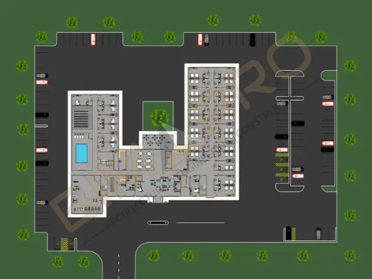
Pool Design in Dubai, UAE
Green Creation is a distinguished international firm specializing in bespoke luxury projects within the commercial and residential sectors across the UAE. Our team of consultants, designers, engineers, and contractors excels in delivering customized solutions, overseeing every phase from design to construction with precision and expertise. With over 20 years of experience in swimming pool construction, including filtration, heating, and ventilation systems, we ensure the highest standards of quality and attention to detail. Each swimming pool project is meticulously monitored to meet rigorous standards, guaranteeing years of enjoyable and safe swimming. From initial consultation to final installation, Green Creation offers comprehensive support, integrating the latest advancements in pool technology and methods. Whether designing a new pool or refurbishing an existing one, our services are tailored to meet your unique requirements. Contact Green Creation today to start designing the pool of your dreams.
Swimming Pool Construction in Dubai
Our highly skilled designers bring years of experience in creating top-tier swimming pools, water treatment systems, water features, hydro-spas, and various civil engineering projects in and around Dubai, UAE. Utilizing advanced CAD technology, we produce precise design documentation, allowing for efficient review and approval of concept drawings. This process facilitates seamless transition from design to construction, supported throughout by our dedicated design team. Our expertise encompasses a range of pool types, including:
Fitness Pools - We can enhance your pool, whether new or existing, with a current system that creates a smooth, powerful current. This feature provides all the benefits of swimming, including cardiovascular fitness and low-impact workouts, in the comfort of your home. It is ideal for aqua aerobics, hydrotherapy, and water jogging, with adjustable settings and easy operation via an ON/OFF switch. The Fast Lane system adds versatility and functionality to your pool.
Swim Spas - Combining a swimming pool with a spa, swim spas feature a current system alongside luxury spa amenities such as hydrotherapy jets and an underwater treadmill. Perfect for those who enjoy aquatic exercise followed by relaxation, swim spas offer year-round fitness and the soothing benefits of a hot tub.
Indoor Pools - With over a decade of experience in constructing indoor swimming pools, we offer a range of solutions from basement pools to rooftop installations. Our expertise extends to transforming stately homes, barn conversions, and new pool house extensions. We collaborate with clients to bring their design visions to life, sourcing high-quality products globally to ensure exceptional finishes and value for money.
Outdoor Pools - Our advanced building and design techniques enable us to create the ideal outdoor swimming pool for your garden. We provide guidance on efficient pool maintenance, including energy-saving heat pumps, cutting-edge water treatment systems, and year-round pool covers. Additionally, we offer a variety of accessories, such as water fountains and underwater lighting, to enhance your pool’s appeal and functionality.
Commercial Pools - Serving schools, hotels, parks, health clubs, and leisure centers, Green Creation is a leading expert in commercial pool design and installation. Our team manages projects of various sizes, delivering turnkey solutions from the initial concrete base to the final finishing touches, with a focus on technology and quality.
Infinity Pools - Infinity pools represent the pinnacle of luxury, seamlessly blending with their surroundings to create a stunning visual effect. We offer several options for designing infinity pools, which provide the illusion of an endless expanse of water. With the right backdrop, such as a lake or sea, an infinity pool creates a breathtaking feature that enhances any architectural project.
Swimming Pool Maintenance in Dubai
Green Creation offers exceptional cleaning and maintenance services for residential and commercial pools throughout the UAE. Our services are competitively priced and designed to be hassle-free, reflecting our passion for pool care. We address a range of needs, from minor repairs to complete pool replacement. Our on-site consultations quickly assess damage and present options for restoration. We handle decking, patio, pool, and spa repairs, update pool equipment, install safety-compliant drains, clean gunite surfaces, replace vinyl liners, install automatic covers, and conduct various diagnostic tests including water pressure and underground leak assessments.
#landscape maintenance dubai#pool maintenance dubai#landscaping companies in dubai#landscaping in dubai#pool design dubai#pool repair dubai#pool service dubai
0 notes
Text
Precision and Performance: Enhancing Projects with Expert Piping Design and 3D BIM Modeling
In today’s competitive construction and industrial environments, precision, efficiency, and innovation are the cornerstones of success. One of the most critical elements in achieving these goals—especially for mechanical systems—is accurate and detailed piping documentation. At Advantage Engineering Technologies, PLLC, we specialize in delivering pipe fabrication drawings, precise piping design drawings, and cutting-edge 3D BIM modeling services that streamline construction and improve project outcomes.
Why Piping Design Is a Cornerstone of Industrial Success
Piping systems are vital to the operation of mechanical, chemical, HVAC, and utility infrastructures. Whether it's transporting steam, water, oil, or gas, an efficient piping layout is crucial to operational efficiency and safety.
That’s where expert piping design drawings come into play. These detailed drawings serve as a visual guide for fabricators, contractors, and engineers. They map out the entire pipe system, including fittings, valves, support systems, and routing paths.
At Advantage Engineering Technologies, our piping design team ensures:
Optimal routing to minimize material waste
Accurate sizing to meet flow requirements
Full compliance with industry standards and codes
Conflict-free coordination with structural and architectural components
This level of precision ensures minimal rework, smoother project execution, and long-term system durability.
Pipe Fabrication Drawings: The Blueprint for Precision Manufacturing
While piping design drawings focus on the layout and system design, pipe fabrication drawings serve as a detailed manufacturing guide. These drawings break down the pipe system into individual spools or segments, complete with exact dimensions, weld points, and materials required.
At Advantage Engineering Technologies, PLLC, our pipe fabrication drawings include:
Isometric views for easy visualization
Weld and joint types for field accuracy
Bill of materials (BOM) with item codes and quantities
Spool maps for logical fabrication and assembly
Inspection points for quality control
By providing this level of detail, we help fabricators build piping systems accurately and efficiently—reducing costly errors, project delays, and field adjustments.
The Power of 3D BIM Modeling Services
Today’s construction environment demands more than just 2D schematics. That’s why we offer advanced 3D BIM modeling services to integrate your piping systems with architectural, structural, and MEP components.
Building Information Modeling (BIM) transforms project planning by offering a centralized, intelligent 3D model that supports:
Clash detection: Identify and resolve conflicts before construction begins
Visualization: Provide clients and stakeholders with a clear project overview
Coordination: Improve collaboration among trades and reduce field changes
Construction sequencing: Plan installation timelines and reduce idle time
Lifecycle management: Maintain accurate data for future operations and maintenance
At Advantage Engineering Technologies, our 3D BIM models incorporate precise geometry and technical data for every pipe, valve, support, and equipment unit. This results in better planning, faster installations, and long-term savings.
Why Choose Advantage Engineering Technologies?
Choosing a reliable partner for piping design drawings, pipe fabrication drawings, and 3D BIM modeling services is crucial for successful project delivery. Here’s why Advantage Engineering Technologies, PLLC is the go-to partner for engineering excellence:
1. Experienced Team of Engineers
Our team comprises skilled mechanical engineers, CAD professionals, and BIM modelers with years of experience across commercial, industrial, and institutional projects.
2. Customized Solutions
We tailor our services to each project’s scope, scale, and technical requirements—ensuring that all deliverables are practical, buildable, and code-compliant.
3. Technology-Driven Approach
We utilize the latest tools including AutoCAD Plant 3D, Revit, Navisworks, and SolidWorks to deliver high-precision models and drawings.
4. Full Project Support
From conceptual design to fabrication and field support, our engineers work alongside architects, contractors, and project managers at every stage.
5. Commitment to Quality and Deadlines
We are known for delivering accurate drawings and models on time, every time—helping clients stay on schedule and within budget.
Applications We Support
Our pipe fabrication drawings, piping design drawings, and 3D BIM modeling services are applicable across a wide range of industries, including:
HVAC and Mechanical Piping
Oil & Gas and Process Piping
Pharmaceutical and Food Manufacturing
Chemical Plants and Refineries
Data Centers and Utility Infrastructure
Water and Wastewater Treatment Facilities
Whether it's a high-rise mechanical room or a complex industrial plant, we provide scalable solutions that ensure efficiency and reliability.
How Our Process Works
Our streamlined engineering workflow is designed to keep your project on track:
Project Kickoff – We gather all architectural, structural, and MEP inputs.
Concept Design – Our team drafts the initial layout for client review.
Detailed Modeling and Drawings – We create accurate 2D and 3D deliverables, including fabrication details.
Clash Detection and Revisions – Using BIM tools, we identify and fix any system conflicts.
Final Delivery – Fully coordinated, construction-ready drawings and BIM models delivered in your preferred format.
Final Thoughts
In an industry where time is money and accuracy is critical, don’t leave your piping design and coordination to chance. At Advantage Engineering Technologies, PLLC, we bring a meticulous, modern approach to pipe fabrication drawings, piping design drawings, and 3D BIM modeling services. Our solutions help reduce errors, boost efficiency, and improve project outcomes.
0 notes
Text
Raster to Vector Services | USA’s Trusted Source for Quality Conversions in 2025
In today’s fast-paced digital world, raster to vector services are necessary for businesses, designers, architects, and manufacturers, especially across the USA. Whether you are dealing with old blueprints, hand-drawn sketches, or low-resolution logos, converting them into clean, scalable vector graphics is essential.
Raster images, composed of pixels, often lose clarity when resized. Vectors, however, maintain quality at any scale. This is why many companies in the USA are increasingly relying on raster to vector services to enhance their projects' accuracy and professionalism.
Understanding raster to vector services is crucial if you're searching for a reliable solution to upgrade your artwork or technical drawings. Let’s dive deep into what they are, why they're important, and how businesses across the USA benefit from them.
What Are Raster to Vectorhttps://www.digitemb.com/services/raster-vector-services/ Services?
Raster to vector services involve converting pixel-based images (raster images) like JPG, PNG, or BMP files into vector formats like AI, EPS, or SVG. Raster images consist of thousands or millions of tiny pixels, which can cause the image to appear blurry when zoomed in. On the other hand, vector images are made using mathematical formulas, ensuring they remain sharp and clear at any size.
In the USA, industries such as engineering, apparel, architecture, and graphic design heavily depend on accurate and scalable images. Thus, raster to vector services have become an integral part of many workflows. Whether you need to prepare artwork for printing, create CAD drawings, or improve branding materials, this conversion ensures the highest level of quality and professionalism.
Why Are Raster to Vector Services Important?
In the competitive market of the USA, quality can make or break a brand. Blurry logos or unclear designs can damage your company's reputation. Raster to vector services guarantee that your visuals maintain consistency, clarity, and precision across all media.
Here’s why these services are so vital:
Scalability: Vectors can be resized indefinitely without losing quality.
Editability: Once vectorized, components of the image can be edited individually.
Professionalism: Sharp, clean designs reflect a brand’s quality.
Printing Accuracy: High-resolution printing demands vector formats for best results.
Many companies in the USA choose professional providers for their raster to vector services needs to ensure that their materials are ready for both digital and print applications.
How Does the Raster to Vector Conversion Process Work?
The process of converting raster images to vector graphics involves several key steps:
Image Analysis: Assessing the quality and complexity of the raster image.
Tracing: Using software or manual techniques to trace the outlines and details.
Layer Creation: Organizing the design into layers for easy edits.
Final Adjustments: Cleaning up the image, fixing any distortions, and enhancing lines.
Output: Delivering the file in the required vector format (such as AI, EPS, PDF, or SVG).
Professional raster to vector services in the USA often blend automated tools with skilled manual editing to ensure the highest fidelity and attention to detail.
Applications of Raster to Vector Services
Raster to vector services are widely used across various industries in the USA:
1. Architectural and Engineering Drawings
Blueprints and technical schematics often exist as old, scanned raster files. Vectorization helps in converting them into CAD files that can be modified and used for renovations, 3D modeling, and construction planning.
2. Apparel and Embroidery Designs
In the fashion and textile industries, especially in hubs like New York and Los Angeles, accurate designs are crucial. Vector files ensure embroidery machines and screen printers produce precise results.
3. Graphic Design and Branding
Marketing agencies across the USA heavily depend on raster to vector services to create logos, banners, and other promotional materials that look flawless both online and in print.
4. Manufacturing and Product Design
Manufacturers use vector files to create prototypes, packaging designs, and instructional manuals. A scalable vector ensures there are no errors during production.
Benefits of Hiring Professional Raster to Vector Services
While there are many online tools available, nothing beats the quality and reliability of professional raster to vector services providers, especially in the USA.
Some top benefits include:
Accuracy: Professionals ensure all lines, curves, and colors are perfectly recreated.
Time-Saving: Experts can deliver faster, allowing businesses to meet tight deadlines.
Customization: Need specific file formats, color adjustments, or layering? Professionals tailor the output to your needs.
Consistency: For brands maintaining strict guidelines, consistency in visuals is key.
Choosing a reputed raster to vector services company in the USA means your business gets high-quality outputs that can drive growth and enhance your visual branding.
How to Choose the Best Raster to Vector Services Provider
Selecting the right provider is crucial. Here's what you should consider:
Experience: Check how long they've been offering raster to vector services.
Portfolio: Review their past projects and clients.
Turnaround Time: Fast delivery is essential for businesses with tight schedules.
Pricing: While cost is a factor, don't compromise quality for a lower price.
Customer Support: Good communication ensures you get exactly what you need.
Across the USA, many businesses rely on recommendations and reviews to find trustworthy raster to vector partners. Make sure you vet your service provider carefully!
Common Challenges in Raster to Vector Conversion
Even the best raster to vector services face certain challenges:
Low-Quality Inputs: Poorly scanned or pixelated images are harder to convert cleanly.
Complex Artwork: Highly detailed images require more manual attention.
Color Matching: Ensuring that colors stay true during the conversion can be tricky.
File Size Management: Large vector files can be heavy; optimizing without losing quality is a skill.
Professional providers in the USA use advanced techniques and meticulous quality checks to overcome these challenges efficiently.
Future Trends in Raster to Vector Services
The future looks bright for raster to vector services in the USA and globally. With technological advancements:
AI-Powered Conversion: Artificial Intelligence is speeding up the conversion process without compromising quality.
Cloud Integration: Easy sharing and collaboration on cloud platforms is becoming the norm.
Higher Demand in New Industries: Industries like augmented reality (AR) and virtual reality (VR) are starting to rely on vector graphics for better performance.
Staying updated with these trends ensures that your business remains competitive.
Conclusion: Why Raster to Vector Services Are a Must for Your Business
In summary, raster to vector services are essential for any business or individual that deals with images, designs, and technical drawings. From ensuring scalability to enhancing professionalism, the benefits are enormous.
If you are in the USA and looking to take your visual content to the next level, investing in professional raster to vector services is a smart move. It not only boosts your brand image but also ensures that you are prepared for any project demands, whether in digital or print media.
Don’t let poor-quality images hold you back — transform your visuals today with the best raster to vector services available!
0 notes
Text
How to make a PCB

Today, I will cover in detail and show the process of making a printed circuit board at home. In addition to a soldering iron and a pair of side cutters, you will need a laser printer, an iron, a micro drill, and a few other tools for this job.
I test my designs on traced PCBs and do not use universal prototyping boards. It’s more convenient for me personally, and here’s why.
On the one hand, tracing a PCB takes time. On the other hand, it is also required to carefully arrange components and connections on a universal board. Additionally, you will need to cut traces on a stripboard or, on the contrary, make the traces you need on a breadboard if it is a matrix of pre-drilled holes with separate copper pads.
A board designed in CAD can then be copied in any number, either by making it yourself or by ordering from a factory, all new and shiny, already with a solder mask and silkscreen printing.
Finally, repairing and modifying a circuit on a printed board can be easier than on a universal one. Especially if long pins of the components on a universal board are used as tracks.
So, I drew the scheme in Schematic Editor, part of the KiCad 7.0 software package. This will be a microphone preamp; I will describe it more thoroughly in the upcoming posts. Moreover, this essay is on making the actual board, not its schematics.

Next, one needs to run the footprint assignment tool and specify the footprint for each and every component.

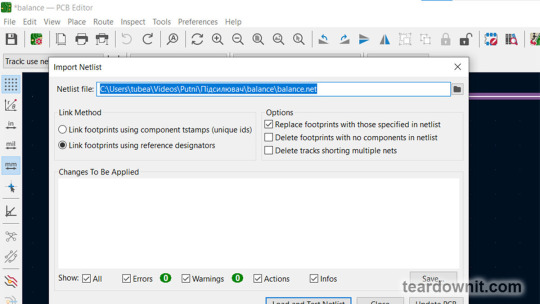
Then, we need to export the netlist.

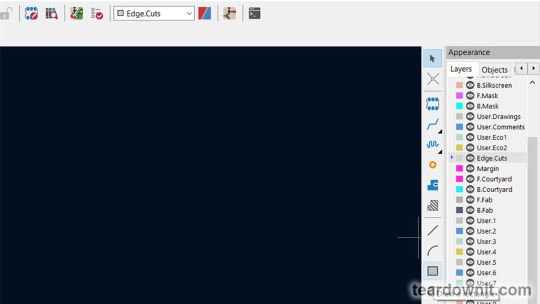
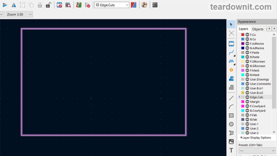
On the Edge. Cuts layer draw a rectangle that specifies the dimensions of our future PCB.
Now, we need to lock that rectangle so that it does not stand out too much and prevent it from being changed while we continue to draw our board layout.
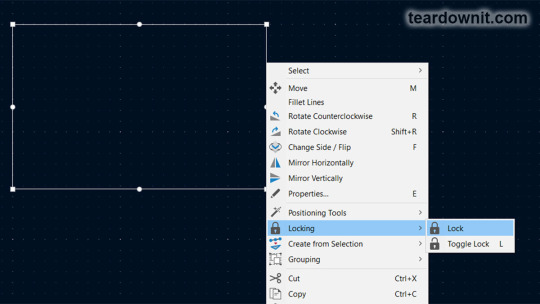
One should ensure the Locked Items checkbox is unchecked on the Selection Filter.
Next, open PCB Editor and import the netlist.

Click Load and Test Netlist, and then Update PCB.
Then, you can place the components and draw the tracks.

We can view a 3D model of the future board at any time.

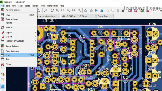
Once all the components are in place and the traces and polygons are drawn, one can print an image of the copper layer. You should turn off the toner save mode on your laser printer.
You can use glossy photo paper (designed for inkjet printing), any pages from glossy ad brochures or magazines, or special heat transfer paper for laser printers from electronics enthusiasts' stores. It is often colored yellow.
My board is single-sided, with all the components on the front side and all the copper on the backside. Therefore, we select the B.Cu and Edge.Cut layers for printing. The print scale should be 1:1.
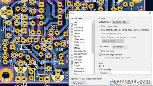
If printing the front copper layer of F.Cu, we need to check the "Print Mirrored" checkbox.
Next, you must cut out a board of the required size from foil fiberglass. Some of us have access to professional cutters or use tin snips.
Others can utilize a rotary power tool with a cutting wheel or even an angle grinder. This is not the best option since fiberglass dust contains microscopic glass particles that irritate the skin and are very harmful if inhaled.
Due to its material, fiberglass PCB quickly dulls any tool except a diamond one. You can see the PCB with a hacksaw, but it will end up its teeth very quickly.
I use an adjustable tile hole cutter for cutting fiberglass. It contains two carbide cutters that can scratch a deep groove in the board and then simply break it along this groove.

These cutters are specifically designed for working on rigid materials, so CEM will not soon dull them. With this technique of cutting the PCB by scraping the track, we minimize the amount of glass dust and do not scatter it in the air.
Next, you need to carefully clean the surface of the copper foil. You can use the finest sandpaper, mild abrasive powder, or steel wool for dish cleaning. I use just a hard eraser. The point of cleaning is not only to remove dirt, oils, and oxides but also to cause micro-scratches for the toner to stick to.
Immediately after, the board must be thoroughly washed to remove any small foreign particles, then fried and degreased with acetone, lighter fluid, ethyl, or isopropyl alcohol.
So, we have a clean, dry fiberglass blank and a piece of glossy paper with traces printed on it. Textolite and paper are the same size. I fold them together and wrap them in a layer of office paper, newspaper, or, better yet, rolling paper.
Thin paper is needed so the glossy paper does not move relative to the PCB. Now, we place the wrapped board blank on a heat-resistant flat surface that we don't mind getting dirty. I use a stack of a few cardboard packaging sheets.
We take the iron, turn it on, and set the temperature as high as it goes. We place it on the blank board and iron it for three to four minutes so the blank has time to warm up nicely.
There is no need to press too hard, but the pressure should be firm. The skill comes with experience. To hold the hot workpiece while ironing, you can use a chopstick.
Remove the iron from the board and turn it off. Remove the wrapping paper from the board after it has cooled off, and place the PCB and the glossy paper in a warm water bath.
Next, slowly and carefully tear off the paper piece by piece from the fiberglass. The tracks and pads on the copper foil should be imprinted.

If some part of the board's design comes off, it can be restored with a permanent marker after the board is completely dry. If a significant piece of the polygon has fallen off, you can just tape it.
Next, I glue strips of tape on the non-foil side of the board to make small hanging rings to hold the board while etching. Throwing a chopstick through these rings is convenient to keep the board hanging. For etching to occur evenly, the board must be swiveled from side to side to mix the solution.

I use a ferric chloride solution for etching, which can be used multiple times. You can store it in a plastic or glass container with a non-metallic lid. This poisonous solution will corrode almost any metal, including stainless steel, so it should be stored, marked, and used cautiously.
To prepare an etching solution, you must take water at room temperature, pour it into a non-metallic container, and add ferric chloride little by little, stirring until the ferric chloride stops dissolving.
The solution will heat up during the dissolution process, not as much as when slaking lime, but noticeably. There is no need to filter the prepared solution or remove the sediment from the bottom of the container.
The optimal temperature for etching the board is 105–130°F (40–55°C). You can heat the solution past that, but then it may wash away permanent marker drawings.
I use plastic food containers for etching and a microwave to heat up the solution. I place the plastic container with the lid loosely closed inside a second bigger one with a lid on and turn on the microwave for one minute. This way, I can be sure that ferric chloride will not damage the microwave.
Once the excess copper on the board has completely dissolved, the board should be immediately washed with plenty of water using a toothbrush. If you do this over a metal sink, be sure not to leave a drop of etching solution anywhere; it can eat right through the sink.

Using acetone, we erased the toner from the washed and dried board and began drilling holes with a microdrill.

Trying the board in the case.

Then, you can begin soldering the components immediately. Still, the best results are obtained if you tin the entire copper foil. I use solder paste for this; just remember that it is toxic, and after working with it, you must wash your hands and wipe the table's surface clean.
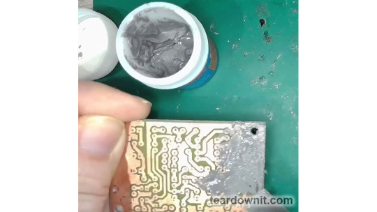
Apply solder paste using a spatula in as thin a layer as possible, as if applying thermal paste to a processor. Next, heat the copper foil with a soldering iron.

Now, wipe or rinse the board with the same degreaser liquid you've used before transferring the toner, and you can place and solder the components.

0 notes
Text
AutoCAD for PV Design: Is It the Right Tool for You?
Designing a solar PV system involves several challenges, from ensuring optimal panel placement to minimizing shading losses. Engineers, designers, and solar professionals often struggle with manual calculations, inefficient workflows, and compatibility issues between different design tools. This is where PV Solar Design Software and PV Design AutoCAD come into play, helping to streamline the process and enhance accuracy.
Let’s explore how these tools solve common design pain points and make solar PV system planning more efficient.
Why Is Solar PV System Design Complex?
Before diving into solutions, it’s important to understand the typical challenges solar designers face:
1. Layout Optimization: Positioning solar panels to maximize sunlight exposure while considering roof or ground constraints can be tricky. 2. Shading Analysis: Trees, buildings, or other obstructions can cause energy losses if shading is not properly accounted for. 3. Electrical Configuration: Designing an efficient wiring and inverter system requires precise calculations. 4. Time-Consuming Manual Workflows: Traditional methods involve using multiple tools that don’t integrate well, leading to inefficiencies.
To overcome these challenges, many professionals turn to advanced PV Solar Design Software and PV Design AutoCAD tools.
How PV Solar Design Software Improves Efficiency
Modern PV Solar Design Software simplifies the entire design process by offering automation, precision, and real-time simulations. Here’s how:
1. Accurate Site Analysis Advanced software allows designers to analyze site conditions using satellite imagery, 3D modeling, and shading simulations. This helps in making informed decisions about panel placement.
2. Automated Layout Planning Instead of manually placing panels, PV Solar Design Software can automatically generate an optimized layout based on the available space and solar potential.
3. Shading and Energy Yield Predictions With integrated shading analysis tools, designers can identify obstructions and adjust panel positions to minimize energy losses, ensuring higher efficiency.
4. Easy Electrical Design & Sizing From string configurations to inverter selection, the software assists in designing electrical connections that comply with safety standards and maximize output.
5. Fast and Error-Free Documentation Instead of manually creating reports, the software automatically generates bill of materials (BOM), single-line diagrams (SLD), and energy production reports, reducing errors and saving time.
By using PV Solar Design Software, designers can significantly reduce planning time, improve accuracy, and increase project profitability.
How PV Design AutoCAD Enhances Solar Projects?
AutoCAD is widely used in engineering and architectural design. When combined with PV Design AutoCAD tools, it becomes a powerful asset for precise solar system layouts and documentation.
Here’s why it’s beneficial:
1. Seamless Integration with CAD Workflows Many solar projects require detailed CAD drawings. PV Design AutoCAD plugins allow engineers to create, modify, and optimize solar layouts directly within AutoCAD.
2. High-Precision Drawings With CAD-based PV design tools, engineers can generate highly accurate roof layouts, mounting structures, and wiring diagrams.
3. Automated Calculations Instead of manually calculating distances, angles, and panel placements, PV Design AutoCAD tools can automate these tasks, reducing design errors.
4. Exporting to Other Solar Design Software Designers can easily export AutoCAD-based PV layouts to specialized PV Solar Design Software, ensuring a smooth workflow between different tools.
5. Compliance with Industry Standards AutoCAD-based PV design tools often come with pre-built templates and regulatory compliance checks, ensuring that designs meet local and international standards.
By integrating PV Design AutoCAD into the workflow, solar engineers can save time, enhance design accuracy, and streamline project documentation.
Which Tool Should You Choose?
Both PV Solar Design Software and PV Design AutoCAD play essential roles in solar PV planning.
If you need automated layout generation, energy yield predictions, and shading analysis, go for PV Solar Design Software.
If your workflow involves detailed CAD-based engineering drawings, then PV Design AutoCAD is the best choice.
For maximum efficiency, combining both tools will ensure a smooth, precise, and optimized solar design process.
For advanced PV design solutions, you can explore tools like Virto Solar and Virto CAD, which provide robust features for efficient solar system planning.
Final Thoughts
Designing a solar PV system doesn’t have to be complex. By leveraging the power of PV Solar Design Software and PV Design AutoCAD, engineers and designers can automate tedious tasks, reduce errors, and enhance project efficiency.
As solar energy adoption grows, investing in the right design tools will save time, improve accuracy, and maximize energy output, ensuring the success of solar PV projects.
#Solar Design Software#Solar Design Tool#PV Design Software#Solar PV Design Software#Solar PV Design
0 notes
Text
Crafting The Art of Metal Wall Decor with DXF Files
Metal wall artwork is a famous choice for people wishing to feature a hint of refinement and aptitude in their houses. The incredible patterns and durability of steel artwork portions set them apart, changing any room into a work of beauty. With the creation of virtual equipment, generating excellent steel wall artwork has in no way been less difficult, as a result of the supply of DXF documents and easy dxf download. Here, we'll have a look at how those assets might also help you recognize your inventive goals.
The Magic of Metal Wall Art
Metal wall art is a unique combination of beauty and modernism. These artistic endeavors can range from difficult geometric styles to abstract motifs, every offering a unique tale. The splendor of metal wall artwork is its adaptability, which permits it to shape a wide range of décor types. Whether you like a minimalist or eclectic look, steel wall artwork may additionally improve the visible elegance of your house or enterprise.

Understanding DXF files
DXF documents, or Drawing Exchange Format files, are extraordinarily crucial inside the realm of digital design and manufacturing. These documents are used to exchange complete design data across several CAD (Computer-Aided Design) structures. For metal artists and fabricators, DXF files give the accuracy required to produce detailed metal wall art. Using DXF files, designers can verify that their works are precisely translated into real components.
Smooth Design Transfer with DXF Downloads
The availability of DXF downloads makes it easy to get the right of entry to high-quality DXF documents. Websites together with DXF for CNC offer a wide selection of DXF documents for download, catering to numerous layout necessities. These downloads provide artists with ready-to-use documents that can be speedy loaded into CNC (Computer Numerical Control) equipment for accurate reduction and engraving. DXF documents make the manner of designing metallic wall artwork extra streamlined and green.

Creating Custom Metal Wall Art
Custom metal wall art is a fascinating project for folks who enjoy personalizing their environments. DXF documents let you create personalized pieces that constitute your own style and character. The versatility of DXF files lets you test with diverse paperwork, patterns, and sizes. Whether you need to make a statement in your living room or a subtle accessory in your administrative center, customized metal wall artwork gives a bit of persona to any environment.
Benefits of Using DXF Files for Metal Art
The usage of DXF files in metal art has various benefits. First and foremost, DXF files provide design precision, which is critical for delicate metal art pieces. These files are extremely easy to modify and scale, allowing artists to adjust their designs as needed. Furthermore, DXF documents are like-minded with several CNC machines, making the production method clean and brief. Using DXF files lets artists keep time and sources at the same time as maintaining the quality of their work.
Enhancing Interiors with Metal Wall Art
Metal wall art may substantially improve the aesthetics of residential and business settings. These art pieces give texture and complexity to walls, making them the center focus of any area. Metal wall artwork isn't always the best visually stunning, however, it is also strong and long-lasting, making it a remarkable investment. Metal wall art may provide a classy and modern touch to your design, leaving a lasting impact.
Exploring design possibilities
The options for metal wall art ideas are almost endless. DXF files let you explore a vast variety of styles, from current and commercial to traditional and ornate. The availability of DXF documents gives you access to a massive library of designs, allowing you to discover the best suit for your aesthetic tastes. Whether you're an expert artist or a DIY enthusiast, the correct DXF files may also spark your next steel artwork venture.
Conclusion
Metal wall artwork is a unique and elegant manner to enhance your home. Using DXF files and DXF downloads, you can produce mind-blowing, precise, and bespoke metal artwork works. Discover the giant range of designs available at DXF for CNC and unharness your creativity now. Transform your own home with lovely metal wall artwork that represents your very own style and provides a hint of refinement to your décor.
0 notes
Text
BIM for Architectural Drawings: Smarter, Faster, Better

Architectural Drawings and How BIM Can Help
Architectural drawings are at the core of every construction project. They are not just sketches or technical sheets; they are the language architects use to communicate their design ideas to clients, contractors, engineers, and everyone involved in the building process. These drawings translate concepts into physical structures, guiding the entire construction journey from start to finish.
But producing architectural drawings, especially for large or complex projects, is no small task. It involves accuracy, coordination, and continuous updates. Traditionally, this process could be slow, repetitive, and prone to errors. That’s where Building Information Modeling, or BIM, changes the game. BIM offers a smarter, faster, and more coordinated way of producing architectural drawings—redefining how we design and build today.
What are Architectural Drawings?
Architectural drawings are the visual and technical representations of a building’s design. These drawings serve multiple purposes—communicating design intent, securing approvals, coordinating with different teams, and guiding construction. There are various types of architectural drawings, each serving a unique role in the project lifecycle.
For example, floor plans show the layout of spaces like rooms, corridors, and circulation paths. Elevations give a look at the external appearance of a building from different sides. Sections offer a sliced-through view of the building, helping us understand how different levels and spaces relate vertically. Then there are detail drawings, which zoom in on construction elements like wall joints or window frames. And let’s not forget schedules, which list components like doors, windows, finishes, and materials—all essential for procurement and execution.
Each of these drawings must be precise and consistent across the board. A mistake in a single view can lead to confusion, delays, or costly errors during construction.
Traditional Process: The Old Way of Doing Architectural Drawings
In the past, architectural drawings were created either by hand or using 2D CAD software. While CAD was a step forward from hand-drafting, it still treated each drawing as a separate file or view. For instance, if you moved a door on the floor plan, you had to remember to adjust it in every elevation, section, and schedule manually. This led to a lot of repetitive work, and worse—if you missed something, it could cause inconsistencies and errors down the line.
Coordination with structural and MEP (Mechanical, Electrical, Plumbing) disciplines was also challenging. Each discipline worked in its silo, and clashes were often discovered only during construction. That meant time-consuming RFIs, rework, and budget overruns.
How BIM Transforms the Architectural Drawing Process
BIM, short for Building Information Modeling, introduces a revolutionary approach. Instead of separate, disconnected drawings, BIM creates a centralized, intelligent 3D model of the building. All architectural drawings—floor plans, elevations, sections, schedules—are automatically generated from this model. They’re not just drawings; they’re live views of the building data.
Let’s say you move a wall in the BIM model. That change instantly reflects in the floor plan, elevation, and even the room area schedule. No need to go into each view and update manually. This real-time coordination saves hours of work and ensures consistency across all deliverables.
BIM also enables parametric design, where building elements like walls, windows, and doors carry information. You can tag a door once, and its size, type, and material can automatically populate in the door schedule. This level of intelligence dramatically improves accuracy and efficiency.
BIM Software for Architectural Drawings
When it comes to creating architectural drawings with speed, accuracy, and intelligence, BIM software has become the go-to tool for architects around the world. These programs go beyond just drawing lines—they help you build an actual 3D model of your design, where every wall, window, and door knows what it is, where it’s placed, and how it connects to everything else. From that model, you can automatically generate floor plans, elevations, sections, schedules, and even realistic renderings—all without having to redraw anything over and over again.
One of the most popular BIM tools is Autodesk Revit. It’s widely used in the architecture, engineering, and construction (AEC) industry, and for good reason. Revit lets you model your building in 3D and produces all your 2D architectural drawings straight from the model. If you change something—like move a wall or change a door type—every related drawing updates instantly. That’s a huge time-saver and keeps everything consistent.
Another strong contender is Graphisoft ArchiCAD. It’s especially loved for its intuitive interface and smooth 2D-3D workflow. Like Revit, ArchiCAD allows you to generate all your architectural drawings from a single model. It’s lightweight, easy to use, and works great for both residential and commercial projects.
Then there’s Vectorworks Architect, which combines strong design features with BIM capabilities. It’s particularly good for architects who want more creative control and artistic flexibility while still benefiting from a smart BIM environment. You can model in 3D, produce clean drawings, and even explore early-stage design ideas all in one place.
Allplan is another option, known for its precision and strength in construction detailing. It’s often used in Europe and is great for complex or large-scale architectural work that demands high accuracy in the documentation phase.
Lastly, if you’re just starting out or working on smaller-scale projects, BricsCAD BIM and SketchUp with BIM plugins can be great entry points. They’re simpler but still offer the ability to create models and extract basic drawings and schedules.
Each of these tools has its own strengths, but they all aim to make architectural drawing more efficient, connected, and accurate. Instead of creating each sheet manually, you build a digital twin of your building—and the drawings come to life from there. It’s faster, smarter, and helps you stay focused on what really matters: the design.
How BIM Helps Create Each Type of Architectural Drawing
Floor Plans
BIM software like Revit or ArchiCAD generates floor plans directly from the 3D model. As you design walls, doors, windows, and furniture in 3D, the 2D plan is automatically generated and updated. Dimensions, tags, and room names can also be linked directly to the model data.
Elevations
You don’t need to draw elevations manually anymore. Just cut a view from the model and boom—you’ve got an accurate elevation. Want to change the window style? Update it in the model, and the elevation changes instantly. BIM also handles shadows, material rendering, and even entourage if needed.
Sections
Like elevations, sections are cut directly from the model. This is a huge time-saver. It also means your section will always reflect exactly what’s in your plan—no more discrepancies.
Reflected Ceiling Plans (RCPs)
Creating RCPs in BIM is almost effortless. Lights, HVAC diffusers, ceiling grids—they’re all modeled in 3D. You just cut a reflected view and adjust visibility settings. The coordination between MEP and architectural elements becomes seamless too.
Site Plans
BIM tools help create site plans that include topography, building footprints, landscaping, and utilities. You can even import real-world survey data or geolocation to make the plan more accurate.
Detail Drawings
Details like wall sections, window sills, or foundation joints can be extracted from the model and enhanced with 2D drafting. You get the best of both worlds—automated base drawings with hand-drawn finesse where needed.
Schedules
This is one of BIM’s superpowers. Door, window, and finish schedules are generated automatically from the elements placed in the model. And they’re live—so if you remove a door in the model, it vanishes from the schedule too. No more forgetting to update schedules manually.
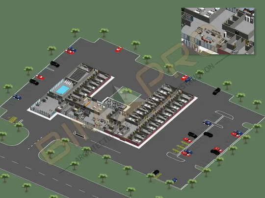
Benefits of Architectural Drawings using BIM
Smarter Drawings with Linked 3D Models
Instead of traditional 2D drafting, BIM lets you create architectural drawings that are directly linked to a 3D model. So when you make a change in the model—say, move a wall or adjust a floor level—the drawings update automatically. No need to chase changes manually across 20 different sheets.
Consistency Across All Views
Plans, sections, elevations, and details all come from the same model. That means you don’t have to worry about one view saying something different than another. BIM ensures all drawings are in sync, reducing coordination errors.
Faster Revisions and Design Updates
Architectural designs evolve fast. BIM makes revisions smoother and quicker. Instead of redrawing everything, you just tweak the model and regenerate the drawings. Huge time saver, especially on tight deadlines.
Accurate Quantities and Takeoffs
With BIM, your drawings aren’t just lines—they carry real data. You can generate door schedules, window counts, and material quantities straight from the model. This makes cost estimation and procurement more precise and reliable.
Better Collaboration with Engineers and Consultants
Since BIM is model-based, architects, structural engineers, and MEP consultants can work on the same platform (or linked models). That means better coordination and fewer clashes on site. Your architectural drawings can also include references to other disciplines for a more complete picture.
Improved Design Visualization
BIM tools let you generate quick 3D views, walkthroughs, and renderings directly from your architectural model. Clients and stakeholders can understand the design better than with flat 2D drawings, making approvals faster.
Code Compliance and Clash Detection
BIM allows you to integrate code checks and run clash detection. For example, you can verify corridor widths, fire exits, or ADA compliance while generating your architectural drawings. It’s like having a built-in checker before you submit for review.
As-Built and Facility Management Ready
Architectural drawings created in BIM can be easily converted to as-built drawings after construction. Plus, they can feed directly into facility management systems, providing long-term value beyond just the design phase.
Version Control and Documentation History
BIM platforms like Revit or BIM 360 track every change. You can roll back, compare versions, or check who changed what and when. This makes documentation management way more transparent and easier to audit.
Sustainability and Performance Analysis
BIM-based architectural models can be used to analyze energy performance, daylighting, and other sustainability factors. These insights can then be reflected in the drawings—for example, showing optimized window sizes or shading devices.
Conclusion: Why BIM is the Future of Architectural Drawings
Architectural drawings are essential—but producing them the traditional way can be tedious and error-prone. BIM brings a fresh, intelligent, and streamlined approach. It eliminates manual repetition, ensures coordination, enhances collaboration, and brings the entire building to life—on screen—before a single brick is laid.
For architects, BIM is more than just a tool—it’s a smarter way of working. It allows them to focus more on design, creativity, and solving real-world problems, while the software takes care of coordination, accuracy, and documentation.
Whether you’re designing a home, a hospital, or a high-rise, using BIM for architectural drawings isn’t just helpful—it’s becoming essential in today’s fast-moving construction world.
#BIMforArchitecturalDrawings#BIMarchitecture#ArchitecturalDrawings#ArchitectsuseBIM#BIMforArchitects#BIMsoftwareforarchitects
0 notes
Text
Mastering Image Design in Adobe Photoshop: Essential Tools and Techniques
Image editing using adobe photoshop : Top Questions Answered
1.How to design a picture in adobe Photoshop?
To design a picture in Adobe Photoshop, start by creating a new document. Use the toolbar for tools like Brush, Shape, or Text tool. Import images or use layers to build your design. Adjust colors, apply effects, and use filters as needed. Save your work in the desired format when finished. Experiment to enhance your skills.
2. What is the difference between adobe Photoshop and AutoCAD?
Adobe Photoshop is a graphic design software primarily used for editing and creating images, focusing on raster graphics. AutoCAD, on the other hand, is a computer-aided design (CAD) software used for creating precise 2D and 3D drawings, mostly in engineering and architecture. Each serves different purposes within their respective fields.
3. What are the 10-layer styles in adobe Photoshop?
The 10-layer styles in Adobe Photoshop are:
1. Drop Shadow
2. Inner Shadow
3. Outer Glow
4. Inner Glow
5. Bevel and Emboss
6. Satin
7. Colour Overlay
8. Gradient Overlay
9. Pattern Overlay
10. Stroke
These styles enhance layers with various effects for creative designs.
4. How many formats are there in adobe Photoshop?
Adobe Photoshop supports numerous file formats for saving and exporting images. The primary formats include PSD (Photoshop Document), PSB (Photoshop Big), JPEG, PNG, GIF, TIFF, and BMP, among others. Each format serves different purposes, such as preserving layers or optimizing for web use. Overall, there are dozens of formats available in Adobe Photoshop.
5. What is the full size of Adobe Photoshop?
The full size of Adobe Photoshop varies depending on the version and platform. Typically, the installation file is around 1.5 to 2 GB, but the total disk space required can be around 4 GB or more after installation. Keep in mind that additional space may be needed for plugins, brushes, and other resources. Always check Adobe's official site for specifics.
Visit: VS Website See: VS Portfolio
0 notes
Text
How Accurate Drafting Enhances Real Estate Development Efficiency

In the fast-paced world of real estate development, efficiency is paramount. From initial planning to final execution, every stage requires precision to ensure that projects meet deadlines, adhere to budgets, and achieve desired outcomes. Among the many factors that contribute to successful real estate development, accurate drafting stands out as a cornerstone. By delivering precise, reliable, and detailed designs, accurate drafting plays a pivotal role in enhancing efficiency across the lifecycle of a real estate project.
This blog explores how accurate CAD drafting impacts real estate development, the tools and techniques involved, and why investing in precision pays dividends for developers.
1. The Foundation of Real Estate Development
Drafting forms the foundation of any construction project. It translates the vision of architects, engineers, and developers into detailed drawings that guide construction teams. Accurate drafting ensures that these designs:
Align with the project’s objectives.
Adhere to building codes and regulations.
Facilitate smooth communication among stakeholders.
Mistakes in drafting can lead to costly errors, rework, and delays. Accurate drafting eliminates ambiguities, ensuring all project participants are on the same page.
2. Streamlining Planning and Approval Processes
Accurate drafting is crucial during the early stages of real estate development when plans need to be presented to regulatory authorities and investors. Detailed, error-free drafts:
Simplify the approval process by meeting compliance standards.
Build investor confidence with professional and precise designs.
Reduce the likelihood of back-and-forth corrections with regulatory agencies.
For example, accurate site plans and layouts that adhere to zoning laws help developers obtain permits faster, accelerating the project timeline.
3. Enhancing Collaboration Among Stakeholders
In real estate development, collaboration is essential. Multiple professionals, including architects, engineers, contractors, and developers, rely on drafting to share their ideas and ensure smooth project execution. Accurate drafting enhances collaboration by:
Providing a clear and unified visual representation of the project.
Avoiding misinterpretations or conflicts in design and execution.
Enabling easy updates and modifications during the project lifecycle.
With tools like CAD software, stakeholders can share accurate drafts digitally, further enhancing communication and efficiency.
4. Reducing Construction Errors and Rework
One of the most significant benefits of accurate drafting is its ability to minimize errors during construction. Clear, precise drafts reduce the likelihood of:
Incorrect material orders.
Misaligned structural components.
Design inconsistencies that lead to rework.
By preventing these issues, accurate drafting saves time and money while maintaining the quality of the project.
5. Leveraging Technology for Greater Accuracy
Modern drafting tools have revolutionized the way real estate projects are designed. Technologies like Computer-Aided Design (CAD) and Building Information Modeling (BIM) offer unparalleled precision and flexibility.
Key Benefits of Using Technology in Drafting:
3D visualization: Stakeholders can view and modify designs in three dimensions, improving accuracy and clarity.
Automation: Tools can detect potential clashes, inconsistencies, or errors in the design phase, reducing rework.
Scalability: Drafts can be easily adjusted to fit changes in project scope or size.
By incorporating these technologies, developers can create drafts that are not only accurate but also adaptive to the dynamic needs of real estate projects.
6. Supporting Sustainable Development
In today’s environmentally conscious world, sustainable real estate development is gaining prominence. Accurate drafting supports this goal by:
Optimizing resource use through precise material planning.
Incorporating energy-efficient designs into the project layout.
Ensuring compliance with green building standards and certifications.
Drafting tools also enable developers to simulate the environmental impact of their designs, ensuring sustainability is built into the project from the ground up.
7. Improving Project Timeline Management
Time is money in real estate development, and accurate drafting ensures that projects stay on schedule. By eliminating errors, reducing approval times, and improving collaboration, accurate drafts:
Shorten the planning phase.
Streamline construction timelines.
Minimize delays caused by design revisions or corrections.
With precise drafts guiding the process, developers can deliver projects faster without compromising on quality.
8. Boosting Cost Efficiency
Accurate drafting directly impacts the bottom line of real estate projects. It helps developers save money by:
Reducing material waste through precise measurements and plans.
Avoiding costly errors and rework during construction.
Enhancing operational efficiency, leading to faster project completion.
Moreover, detailed drafts allow developers to estimate costs more accurately during the planning stage, improving budgeting and financial forecasting.
9. Meeting Client Expectations
In the competitive real estate market, meeting or exceeding client expectations is crucial for success. Accurate drafting ensures that the final product aligns with the client’s vision by:
Capturing every detail of the project requirements.
Offering realistic visualizations and simulations of the design.
Delivering a finished product that matches the approved plans.
Satisfied clients are more likely to recommend developers, enhancing their reputation and opening doors to new opportunities.
10. Ensuring Long-Term Asset Value
Real estate projects are long-term investments, and their value depends on the quality of their construction. Accurate drafting contributes to this by:
Ensuring structural integrity through precise design.
Facilitating future renovations or expansions with clear, detailed plans.
Supporting property maintenance with accurate documentation.
By laying the groundwork for durability and adaptability, accurate drafting safeguards the value of real estate assets over time.
The Role of Professional Drafting Services
Given the critical role of accurate drafting in real estate development, many developers turn to professional drafting services to ensure their projects are executed flawlessly. These services offer:
Access to skilled drafters and advanced tools.
Expertise in industry standards and regulations.
Custom solutions tailored to the unique needs of each project.
Outsourcing drafting services allows developers to focus on their core competencies while ensuring that their designs meet the highest standards of accuracy.
Conclusion
Accurate drafting is the backbone of efficient real estate development. It streamlines planning, enhances collaboration, reduces errors, and supports sustainability, all while saving time and money. By investing in precision at the drafting stage, developers can unlock a cascade of benefits that ripple through every phase of their projects.
In today’s competitive and fast-moving real estate market, accuracy isn’t just a preference—it’s a necessity. Whether you’re planning a residential community, a commercial complex, or a mixed-use development, accurate drafting is your key to success.
Take the next step toward efficiency and excellence in real estate development by prioritizing accuracy in your drafts—it’s an investment you’ll never regret.
#cad drafting services#outsource cad drafting services#cad outsourcing#cad design services#cad outsourcing services#outsource drafting services#cad drawing services#cad design and drafting services#outsourced cad services#cad drafting service#outsource autocad drafting#cad service provider#outsource cad drafting#cad drafting outsourcing services#drafting services in india#outsource cad services#architectural cad drafting services#outsource cad services to india#autocad outsourcing#drafting service in india
0 notes