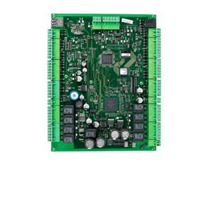
#Advanced Signal and Actuator Module
Explore tagged Tumblr posts
Visit Tumblr Blog
Explore Tumblr blogs with no restrictions, modern design and the best experience.
Last Seen Tumblr Blogs


Fun Fact
The Tumblr app for Google Glass was released on May 16, 2013.
Text
Vehicle Recall: Daimler Trucks Freightliner & Western Star Commercial Trucks:
#25V187000#Advanced Signal and Actuator Module#assistive device failure hazard#Automatic Emergency Braking System#Brake Light failure#Brake Light Software#Brake Lights#crash hazard#Daimler AG of Stuttgart#Daimler Freightliner Trucks#Daimler Trucks North America LLC#Daimler Western Star Trucks#DTNA#Electronics#Forward Collision Avoidance#Freightliner#Freightliner 108SD Commercial Trucks#Freightliner 114SD Commercial Trucks#Freightliner Business Class M2#Freightliner Cascadia Commercial Trucks#injury hazard#NHTSA#reduced visibility hazard#Software defect#US National Highway Traffic Safety Administration ("NHTSA")#Western Star#Western Star 47X Commercial Trucks#Western Star 49X Commercial Trucks
0 notes
Text
Mobile Machine Control Systems: Revolutionizing Off-Highway Machinery
In the rapidly evolving field of automation and smart machinery, Mobile Machine Control Systems (MMCS) are playing a transformative role in improving efficiency, safety, and productivity. These systems, primarily used in construction, agriculture, mining, and other heavy-duty applications, integrate advanced electronics, sensors, actuators, and software to offer precise control and monitoring of mobile machines. As industries strive for increased automation and remote operability, MMCS stands at the forefront of modern machinery technology.
What is a Mobile Machine Control System?
A Mobile Machine Control System is an integrated system that enables real-time control, automation, and monitoring of mobile equipment such as excavators, harvesters, dozers, and forklifts. These systems combine hardware components like controllers, sensors, GPS/GNSS units, and communication modules with sophisticated software for data processing and visualization. The result is a machine that can operate with enhanced accuracy, lower operator input, and greater safety and productivity.
Key Components of MMCS
Electronic Control Units (ECUs): These are embedded systems that act as the brain of the mobile machinery. ECUs receive input from sensors, process the data, and send output signals to control actuators.
Sensors: A wide range of sensors including pressure, temperature, position, and accelerometers are used to monitor the operational status of machines. Sensor data is critical for real-time decision-making.
Actuators: These execute commands from the ECU to carry out physical tasks like lifting, steering, braking, and more.
User Interface (HMI): Operators use Human-Machine Interfaces to interact with the system. Touchscreens, control panels, and even remote controls can serve as the user interface.
Communication Modules: These modules enable the machine to communicate with other systems or control centers using CAN bus, Ethernet, wireless, or cellular networks.
Software Platform: The control software is where the magic happens. It integrates logic, machine learning algorithms, and diagnostic tools to automate and optimize machine operation.
Benefits of Mobile Machine Control Systems
1. Improved Accuracy
MMCS enables highly accurate operation, especially in tasks like digging, lifting, and planting. GPS-guided systems can position machinery within centimeters of the intended location, reducing rework and material waste.
2. Enhanced Productivity
By automating repetitive tasks and optimizing machine performance, MMCS allows operators to complete jobs faster and with less fatigue. Machines can work longer hours with consistent output, increasing overall productivity.
3. Greater Safety
Advanced safety features such as obstacle detection, auto shut-off, and real-time operator alerts help minimize accidents and machine wear. Remote operation capabilities further enhance safety in hazardous environments.
4. Lower Operating Costs
Efficient fuel usage, reduced manual labor, and lower maintenance needs contribute to significant cost savings over time. Diagnostic tools also help predict and prevent costly breakdowns.
5. Data-Driven Decisions
With onboard analytics and cloud integration, MMCS provides actionable insights into machine usage, operator behavior, and job site conditions. This data aids in maintenance planning and operational improvements.
Applications of Mobile Machine Control Systems
Construction
In the construction industry, MMCS is revolutionizing how earthmoving and grading are done. With 3D machine control, graders and dozers achieve perfect surface levels with minimal manual input. This technology reduces the dependency on surveyors and manual stakes.
Agriculture
Precision farming relies heavily on MMCS. Tractors, seeders, and sprayers equipped with control systems can plant seeds with uniform spacing, apply fertilizers accurately, and harvest crops efficiently—all with minimal human intervention.
Mining
Autonomous haul trucks and drilling equipment in mines are examples of MMCS in action. These systems ensure safety in harsh and dangerous environments while maximizing output.
Material Handling
Forklifts and automated guided vehicles (AGVs) in warehouses utilize MMCS to enhance navigation, load handling, and inventory management, boosting efficiency and reducing labor costs.
Challenges in Implementing MMCS
Despite the benefits, adopting MMCS is not without its challenges:
High Initial Investment: The cost of implementing advanced control systems can be significant, particularly for small and mid-sized enterprises.
Complexity: Integrating multiple hardware and software components requires skilled personnel and careful planning.
Interoperability: Ensuring compatibility among various sensors, actuators, and communication protocols can be challenging.
Cybersecurity: As machines become more connected, the risk of cyber threats also increases, necessitating robust security measures.
The Future of Mobile Machine Control Systems
The future of MMCS is intertwined with emerging technologies such as artificial intelligence (AI), machine learning, and the Internet of Things (IoT). Future systems will be even smarter, capable of learning from past operations to improve efficiency automatically.
Remote diagnostics and over-the-air updates will become commonplace, ensuring machines are always running the latest software. Additionally, cloud-based platforms will allow operators and managers to monitor and control equipment from anywhere in the world.
The push toward sustainability will also drive the integration of electric drives and hybrid systems with MMCS, reducing the environmental footprint of mobile machinery.
Conclusion
Mobile Machine Control Systems by Servotechinc are fundamentally changing how industries like construction, agriculture, and mining operate. By combining advanced hardware with intelligent software, MMCS delivers greater precision, safety, and efficiency. While challenges such as cost and complexity exist, the long-term benefits far outweigh them.
As technology continues to evolve, these systems will become more accessible and capable, leading to smarter machines and more productive job sites. For companies seeking to stay competitive in a digital world, investing in Mobile Machine Control Systems is not just an option—it’s a necessity.
0 notes
Text
IRON SPINE: AI-Augmented Spinal Health and Enhancement System
Whitepaper – Cycle 1 of 5000x3 Refinement Process
Abstract
This whitepaper introduces Iron Spine, a non-invasive, AI-driven spinal augmentation and health platform designed to restore, protect, and enhance the spinal and neural systems in both clinical and performance settings. Targeting paraplegics, spinal injury patients, elderly individuals, and physically driven professionals, the system combines neural signal decoding, laser and ionic needle surgical techniques, modular wearable exoskeletons, and AI-assisted rehabilitation. The integration of these systems represents a paradigm shift in spinal care, recovery, and augmentation.
1. Introduction
Advancements in artificial intelligence, biomedical engineering, and neurotechnology have created opportunities for addressing complex spinal disorders and enhancing musculoskeletal function. Iron Spine responds to the unmet need for a modular, intelligent, and minimally invasive spinal health system. It merges non-invasive EEG-based brain-computer interfaces (BCIs), precision therapeutic technologies, and biomechanical support into a unified, adaptive ecosystem.
2. System Architecture
2.1 AI-Driven Brain-Spine Communication
Utilizes non-invasive EEG and neural signal readers to decode motor intention.
Neural-AI relays real-time signals to spinal actuators for motor output.
Bi-directional communication supports feedback loops for posture, pain signals, and rehabilitation status.
2.2 Laser and Ionic Needle Surgery Module
Low-Level Laser Therapy (LLLT) for tissue repair and inflammation reduction.
Ionic needle arrays emit targeted microcurrents to activate or inhibit specific nerve clusters.
Designed for outpatient and long-term wearable integration.
2.3 Spinal Augmentation Frame
A modular exoskeletal brace with micro-actuators for mobility, posture correction, and strength enhancement.
AI-driven “smart memory” mode promotes neuromuscular training and postural consistency.
Expandable with sensory, diagnostic, and rehabilitative attachments.
3. Clinical Applications
3.1 Rehabilitation and Performance Optimization
Adaptive rehab protocols integrate user biometrics and real-time neurofeedback.
Smart mapping of biomechanics aids in motor pathway retraining.
Strength augmentation is governed by safety-centric AI modulation.
3.2 Surgical and Healthcare Integration
Integrates with hospital-based monitoring and diagnostic AI.
Supports recovery from:
Laser-guided nerve repair
Vertebral stabilization
Electro-needle-based pain management
Applications include paraplegia recovery, Alzheimer’s support, and post-stroke mobility enhancement.
4. Intellectual Property Scope
The Iron Spine platform consolidates and protects innovation in the following areas:
Non-invasive ionic microstimulation for spinal intervention
Neural decoding via AI-assisted BCI
Exoskeletal wearables with real-time adaptive control
Cognitive-spinal alignment modules for neuropsychiatric support
Augmented feedback systems for urban and distributed healthcare
5. Future Extensions
Optional implantable extensions for advanced therapeutic or augmentation goals
Wireless mesh compatibility with other body augmentation systems
Rural and emergency deployment via health satellite pods
6. Conclusion
Iron Spine represents a comprehensive reimagining of spinal care, combining wearable tech, AI, non-invasive neuromodulation, and surgical recovery into one coherent system. It holds promise for transforming how spinal disorders and enhancements are treated, offering scalable solutions from the clinic to the field.
Cycle Status:
End of Cycle 1 of 5000x3
Further refinement will iterate on biointerface fidelity, clinical integration pathways, long-term data monitoring, and regulatory pathway frameworks.
0 notes
Text
How do automatic headlights work?
How Automatic Headlights Work: A Technical Breakdown Automatic headlights rely on sensors, control modules, and predefined logic to adjust vehicle lighting based on ambient conditions. Here’s a detailed explanation of their operation:
1. Core Components Ambient Light Sensors: These are typically photoresistors, photodiodes, or cameras installed near the windshield, rearview mirror, or dashboard. They detect changes in external light intensity (e.g., dusk, tunnels, or heavy rain) . Example: A photoresistor’s resistance decreases in bright light and increases in darkness, triggering the system . Electronic Control Unit (ECU): The ECU processes sensor data and sends commands to activate or deactivate headlights. Advanced systems integrate with other modules (e.g., rain sensors or GPS) for context-aware adjustments . Actuators: Relays or transistors physically switch the headlights on/off or adjust brightness (e.g., dimming high beams when oncoming traffic is detected) . 2. Workflow Light Detection: Sensors continuously monitor ambient light. For instance, when entering a tunnel, sensors detect a sudden drop in light intensity . Signal Processing: The ECU compares sensor data against preset thresholds. If light falls below a critical level (e.g., <100 lux), it activates the headlights . Light Activation: Basic Systems: Headlights turn on/off automatically. Advanced Systems: Adaptive Lighting: Headlights swivel with steering input (e.g., RAM 4500’s directional LED system) . High Beam Assist: Automatically dims high beams when detecting other vehicles . Delays and Overrides: Delay Shutoff: Lights stay on for 30–180 seconds after ignition off (e.g., Nissan Armada’s 45-second default) . Manual Override: Drivers can disable auto mode via the headlight switch . 3. Advanced Features Rain-Light Sensors: Some systems link headlights to windshield wipers. If wipers are active for >1 minute, headlights activate regardless of ambient light . GPS Integration: Vehicles with navigation may pre-activate headlights in known low-light areas (e.g., tunnels) . Matrix LED Systems: Pixel-based LEDs block light toward specific objects (e.g., pedestrians) while maintaining full illumination elsewhere. Note: U.S. regulations lag behind Europe in approving such systems . 4. Limitations and User Tips Tunnel Delay: Most systems take 2–5 seconds to activate in sudden darkness. Drivers must manually switch lights in tunnels to comply with traffic laws . Sensor Placement: Dirty or obstructed sensors (e.g., covered by a sunshade) can cause malfunctions . Regional Variations: U.S. vs. Europe: Adaptive headlights with dynamic beam shaping are limited in the U.S. due to outdated regulations . Key Takeaways Automatic headlights blend light sensing, real-time processing, and actuator control to enhance safety. While basic systems focus on on/off functionality, advanced versions integrate with vehicle networks for smarter adaptations. For optimal use, ensure sensors are clean and understand system limitations in extreme conditions.
For deeper technical insights, refer to vehicle manuals (e.g., Nissan Armada ) or regulatory discussions .

#led lights#car lights#led car light#youtube#led auto light#led headlights#led light#led headlight bulbs#ledlighting#young artist#car culture#cars#car#american cars#car light#headlight bulb#headlamp#headlight#Automatic headlight
0 notes
Text
The Role of PCBs in Revolutionizing Industrial Automation
The industrial revolution, characterized by fast technology changes, has created modern manufacturing and production on its backbone. What makes it all happen, though, is the printed circuit board (PCB), the element that allows for seamless functioning in an automated system. All of these, from the programmable logic controllers (PLCs) to robotics, work within the heart of industrial automation to make it efficient, precise, and reliable.
A high-quality PCB card plays a very vital role in industrial automation for providing the reliability and efficiency needed to ensure proper automated processes. Printed circuit boards constitute the heart of control units, sensors, and modules used in communication, through which accurate coordination and processing of data take place. Since they are made up of high-quality PCBs that are able to resist rough industrial conditions, such as high temperatures and vibrations, high-quality PCB cards endure wear and tear, performing optimally in manufacturing and robotics, among other automation processes.
What is a PCB?
A printed circuit board is flat, made of insulating material in the form of fiberglass or composite epoxy. The flat board has conductive pathways etched onto it. In a PCB, various types of electronic components like microprocessors, resistors, capacitors, and sensors have pathways connecting them for work purposes. High-quality PCBs basically act as the spine of electronics, providing support and enabling structural strength and connectivity, further ensuring reliability and durability.
The Importance of PCBs in Industrial Automation:
Industrial automation means that the use of a control system such as computers or robots in the handling of machinery and processes in the production environment. Here, PCBs play a crucial role in the following ways:
Advanced Control Systems: PCBs are vital for the working of PLCs, which is like the brain of the automated systems. They process input from sensors, process data, and control output to actuators. In this way, they ensure accurate and efficient working.
Improving Robotics: In robotics, PCBs are used for controlling movements, processing visual data, and managing communication between various components. The use of high-density PCBs enables compact and lightweight designs in modern robotic systems.
Supporting IoT Integration: The Industrial Internet of Things (IIoT) depends on PCBs for connecting sensors, actuators, and communication modules. These PCBs enable real-time data collection, analysis, and remote monitoring, thus optimizing production processes.
Ensuring Reliability in Harsh Environments: High-quality PCBs, for an industrial automation, are prepared to withstand extreme conditions- high temperatures, humidity and mechanical vibrations. It works consistently in harsh environments so that the downtime and maintenance cost decreases.
Types of PCBs Used in Industrial Automation:
Rigid PCBs: Used mostly in control systems and machines, rigid PCBs ensure strength and stability.
Flexible PCBs: Best for compact devices and systems where the wiring is complicated; they are flexible and can save space.
Rigid-Flex PCBs: The benefits of rigid PCBs and flexible PCBs are combined in rigid-flex PCBs, which are used in advanced robotics and automation systems.
High-Frequency PCBs: They are especially designed for high-speed communication and signal processing in IoT-enabled automation.
Key Advantages of PCBs in Automation:
Miniaturization: PCBs allow various elements to be accommodated within a smaller space, meaning miniaturization and efficiency in equipment.
Precision and Consistency: Automation requires high accuracy and PCBs ensure this in the electrical connections.
Scalability: PCBs are tailored to fit any size industrial equipment, from smaller machines to large manufacturing units.
Cost-Effectiveness: Mass production of PCBs minimizes the cost of manufacture and thus automation reaches many more industries.
The Future of PCBs in Industrial Automation:
With the evolution of technology, PCBs continue to adapt to the emerging trends, such as AI-powered automation, advanced robotics, and IIoT. Multilayer PCBs, new materials, and design techniques that improve upon earlier ones form the pathway to more efficient and sophisticated automation solutions.
Further, the integration of smart PCBs with communication modules and embedded sensors is sure to transform the future of industrial predictive maintenance and real-time monitoring. It will certainly increase productivity and help improve sustainability through the reduction of unnecessary waste and energy consumption.
High-quality PCBs are the unsung heroes behind the intelligence and efficiency of modern systems for industrial automation. Flexibility, reliability, and adaptability make them unavoidable when creating smarter, connected, and sustainable industrial operation. With the continued adoption of automation by industries, the work that PCBs do will only amplify the position they hold to ensure their place in furthering technological advancement.
0 notes
Text
High-Response Tactile Switches in Gaming Devices: Applications and Trends in Esports Keyboards

The booming esports industry has driven gaming device manufacturers to prioritize responsiveness, precision, and tactile feedback. High-response tactile switches have become the cornerstone of devices such as gaming keyboards, delivering unparalleled performance in competitive scenarios. This article delves into their applications, design innovations, and emerging trends.
I. Characteristics of High-Response Tactile Switches
1. Rapid Actuation
Reduced Actuation Point: Traditional tactile switches have actuation points around 1.8-2.0 mm. High-response switches lower this to 0.8-1.0 mm, ensuring faster input during gameplay.
Fast Signal Processing: Paired with advanced controller chips, these switches minimize the latency between keypress and in-game action.
2. Consistent Feedback
Uniform Tactile Response: Ensures every press delivers identical feedback, crucial during high-pressure gaming sessions.
Durability: Lifespans of over 50 million clicks guarantee consistent performance over years of intense use.
3. Customizable Tactility
Different Feedback Options: Players can choose between linear, tactile, or clicky responses tailored to specific gaming genres like FPS or MOBA.
II. Applications in Gaming Keyboards
1. FPS Games: Precision and Speed
First-person shooters demand fast reflexes and precise inputs. High-response tactile switches with reduced actuation distances enable players to execute quick and accurate actions.
Example: A gaming keyboard featuring a 1.0 mm actuation point provided competitive FPS players with the ability to perform rapid-fire actions in CS:GO.
2. MOBA Games: Multitasking Efficiency
Multiplayer Online Battle Arena games require simultaneous multi-key inputs. High-response switches ensure fast skill execution and smooth combinations.
Example: In League of Legends, switches with reduced debounce times enabled seamless multi-skill operations, boosting players' competitive edge.
3. Esports Reliability
Esports events demand equipment that performs flawlessly under extended use. High-response switches designed for tournaments deliver unparalleled consistency and reliability.
Example: A tournament-approved keyboard using switches rated for 100 million clicks ensured uninterrupted gameplay during a major championship.
III. Design and Optimization
1. Material Advancements
Spring Design: High-resilience springs made from beryllium copper provide faster actuation and consistent rebound.
Contact Plating: Gold or silver plating enhances conductivity and prevents degradation over time.
2. Structural Refinements
Shortened Travel Distance: Reducing key travel improves actuation speed while maintaining tactile feedback.
Anti-Wobble Mechanisms: Reinforced housing structures prevent keycap instability during rapid presses.
3. Signal Processing Enhancements
Debounce Optimization: Advanced mechanisms reduce signal noise, ensuring accurate input registration.
Smart Controller Integration: Real-time adjustment of sensitivity based on game type enhances player performance.
IV. Trends in High-Response Tactile Switches
1. Ultrafast Performance
Future switches aim for sub-0.5 mm actuation points and response times measured in microseconds to meet growing demands for speed.
2. Modularity and Customization
Switch modules that players can swap based on game type or preference are becoming more popular, allowing greater flexibility.
3. Optical Switch Integration
Optical technology, which replaces mechanical contacts with light-based triggers, eliminates physical wear and significantly extends lifespan.
4. Sustainability
Eco-conscious designs using recyclable materials and energy-efficient manufacturing processes are emerging as industry priorities.
V. Conclusion
High-response tactile switches have revolutionized gaming devices, providing players with unmatched precision, speed, and durability. By leveraging innovative materials, advanced designs, and cutting-edge technology, these switches cater to the evolving demands of the esports industry. As trends like optical integration and modular customization continue to shape the future, high-response tactile switches will remain at the forefront of gaming innovation, delivering the ultimate competitive edge.
en.dghongju.com
0 notes
Text
Schneider Electric (Erie) At33A00T-3Wire Flt Act,W/ Control Sigtimeout | PartsHnC
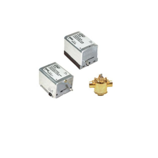
The Schneider Electric (Erie) AT33A00T is a cutting-edge 3-wire floating actuator with a control signal timeout, marking a substantial development in HVAC system control. This advanced actuator precisely modulates dampers, valves, and other equipment in response to control signals.
#Schneiderelectric#SchneiderelectricParts#partshnc#AT33A00T#partshncbuzz#hvacparts#furnaceparts#airconditionerparts
0 notes
Text
Essential Guide: How to Drive a Servo Motor Like a Pro
Servo motors have become vital across various industries, from robotics and CNC machinery to automation. Their precision and control make them ideal for applications requiring specific movement or positioning. For those new to the world of servo motors or anyone seeking to sharpen their skills, understanding how to drive a servo motor effectively is key to harnessing its full potential. This guide will walk you through everything you need to know to drive a servo motor like a pro, covering basics, technical tips, and best practices.

What Is a Servo Motor?
A servo motor is a specialized rotary actuator designed for precise control of angular or linear position, velocity, and acceleration. Unlike traditional motors, which typically run at a constant speed, servo motors respond to specific instructions to move to set positions with a high degree of accuracy. They are commonly used in robotics, conveyor systems, camera focus mechanisms, and beyond.
Key Components of a Servo Motor System
To operate a servo motor effectively, it's essential to understand its components:
Motor – The main driver of motion, either DC or AC, that generates rotational movement.
Controller – Sends specific signals to the motor to reach a target position or speed.
Feedback Device – Typically an encoder or potentiometer, providing feedback on the motor's position to ensure accuracy.
Drive Circuit – Interfaces the controller with the motor, enabling controlled power and precise motion.
Step 1: Choose the Right Servo Motor for Your Application
Choosing the right motor type depends on your application's power, speed, and control requirements. Generally, servo motors fall into two main categories:
DC Servo Motors – Better suited for applications requiring lower power and precise control.
AC Servo Motors – More powerful and suitable for higher-speed applications, often used in industrial automation.
Consider the torque, speed, and voltage ratings as you assess which servo motor fits your needs.
Step 2: Understand Control Signals
Servo motors require control signals to determine movement. There are three main types:
Pulse Width Modulation (PWM) – Common in hobbyist and small-scale applications, it involves sending pulses to control motor position.
Analog Signals – Often used in industrial settings, where a specific voltage range controls motor speed or position.
Digital Signals – A more advanced option that communicates precise instructions for accurate control in complex systems.
Step 3: Master the Basics of Servo Motor Controllers
To drive a servo motor effectively, you’ll need a servo controller, the brain behind the operation. It’s responsible for interpreting the commands and converting them into movements. There are two primary control modes:
Position Control – This mode commands the servo to move to a specified position and is highly accurate.
Speed Control – Here, the controller maintains a steady speed, ideal for applications like conveyor belts.
Selecting the right controller based on your application can make all the difference in achieving optimal performance.
Step 4: Set Up Your Servo Drive
The servo drive is an essential component, bridging the motor and controller. Here’s a basic setup guide:
Power Supply – Connect a power source that matches the servo motor’s voltage and current requirements.
Signal Wires – Connect the control signals from your controller to the servo motor input.
Feedback Mechanism – Ensure the encoder or potentiometer is connected to relay accurate positioning data.
Check Connections – Verify all wiring and connections are correct, ensuring stable performance and avoiding overheating or short circuits.
Step 5: Programming Your Servo Motor
Servo motors can be controlled manually or programmed via a microcontroller or PLC (Programmable Logic Controller) for automation. Start by writing basic commands to rotate the motor to specific angles, then proceed to more complex programs for movement sequences. Popular platforms like Arduino and Raspberry Pi are ideal for beginner programmers.
Step 6: Fine-Tuning Performance
To drive a servo motor like a pro, fine-tuning is necessary. Here are some techniques:
PID Tuning – PID (Proportional-Integral-Derivative) controllers are commonly used to fine-tune servo motors, helping achieve smoother and more precise control.
Frequency Response Tuning – Adjusting frequency parameters can prevent oscillations and improve stability.
Gain Adjustment – Increasing or decreasing gain settings affects responsiveness and precision.
Step 7: Troubleshoot Common Servo Motor Issues
When driving a servo motor, issues may arise. Here’s how to troubleshoot:
Inconsistent Positioning – Verify the feedback device is correctly calibrated and connected.
Overheating – Check that the motor isn’t overloaded and that the drive circuit isn’t providing excessive current.
Unexpected Stopping – Inspect connections, power supply, and control signal integrity.
Noise and Vibration – Adjust gain settings or consider a damper if high-frequency noise affects performance.
Step 8: Regular Maintenance
Regular maintenance ensures optimal servo motor performance and extends lifespan. Here are some maintenance tips:
Check Wiring and Connections – Loose connections can cause erratic movements.
Lubricate Bearings – Especially in industrial environments, to prevent wear and tear.
Inspect Feedback Devices – Clean encoders or potentiometers for accurate data.
Why Learn to Drive a Servo Motor Like a Pro?
Mastering servo motor operation enhances productivity, precision, and cost efficiency. Industries benefit from improved control and accuracy in applications ranging from robotics to medical devices, where precise movement can make a crucial difference.
Conclusion
Driving a servo motor may seem complex initially, but with this guide and hands-on practice, you'll be able to control it confidently. Whether you’re aiming for exact positioning or consistent speed, mastering servo motors will open up opportunities for innovation and efficiency.
0 notes
Text
8 Bit Microcontroller Marvels: How They’re Changing Consumer Electronics

8 Bit Microcontroller Market , where tiny processors wield enormous power. These microcontrollers, the unsung heroes of the tech realm, are designed to perform essential tasks in embedded systems. From controlling household gadgets to driving sophisticated industrial machinery, they ensure that our daily lives run smoothly. The 8 Bit Microcontroller Market emerged in response to a growing need for efficient, cost-effective solutions to perform fundamental computing tasks. As industries began automating processes, the demand for reliable control mechanisms surged. Picture the late 1970s: a time when bulky, expensive computing systems dominated. Enter the 8-bit microcontroller, a game changer that democratized technology, making automation accessible to many.
The journey began in 1976 with the introduction of the Intel 8048 microcontroller. Intel, a pioneer in semiconductor technology, laid the groundwork for the 8 Bit Microcontroller Market. This breakthrough not only simplified design but also inspired countless innovations, setting the stage for a thriving ecosystem of microcontrollers that we see today. The evolution of the 8 Bit Microcontroller Market is a testament to human ingenuity. Initially, these microcontrollers served basic functions like turning lights on and off, controlling motors, and managing simple tasks. Fast forward to today, and you’ll find them integrated into everything from smart refrigerators to wearable fitness trackers. With advancements in technology, today’s 8-bit microcontrollers boast features like integrated peripherals, enhanced memory, and higher processing speeds. As the Internet of Things (IoT) gained momentum, the market transformed, catering to the need for connectivity and smart functionality. The 8 Bit Microcontroller Market has diversified, with innovative solutions emerging from unexpected corners, driven by startups and established giants alike.
Understanding the 8 Bit Microcontroller Architecture
At its core, the 8-bit microcontroller is defined by its ability to process data in 8-bit chunks, meaning it can handle 8 bits of data simultaneously. While this may seem limited compared to more advanced 16-bit or 32-bit microcontrollers, 8-bit devices excel in simplicity and efficiency, especially for tasks that do not require complex processing. Their reduced architecture translates to lower energy consumption, a vital trait in a world increasingly driven by portable and battery-powered devices.
Within the 8-bit microcontroller ecosystem, various peripherals and modules play essential roles. These include timers, analog-to-digital converters (ADCs), pulse-width modulation (PWM) controllers, and communication interfaces like I²C, UART, and SPI. Together, they form the backbone of any embedded system, allowing microcontrollers to interact with sensors, actuators, and other digital systems. For instance, in automotive applications, PWM controllers manage motor speeds, while ADCs convert real-world signals like temperature or voltage into data the microcontroller can process.
Developers find the simplicity of 8-bit microcontrollers appealing, as they can often design effective solutions with minimal programming effort. Moreover, a wealth of open-source libraries and development tools exists to support 8-bit microcontroller development, lowering barriers to entry and encouraging rapid prototyping.
Innovation and Advancements in 8 Bit Microcontrollers
Innovation in the 8 Bit Microcontroller Market is far from stagnant. The evolution of semiconductor technologies has allowed these microcontrollers to pack more features into smaller, cheaper packages. Manufacturers are constantly pushing the limits of what an 8-bit microcontroller can achieve by incorporating more memory, enhanced peripherals, and optimized power management techniques.
One particularly interesting development is the integration of Artificial Intelligence (AI) capabilities into 8-bit microcontrollers. While AI is typically associated with high-performance computing platforms, microcontrollers are finding a place in edge computing applications, where data processing occurs locally on the device rather than in the cloud. In such scenarios, lightweight AI algorithms allow 8-bit microcontrollers to perform tasks like object detection or predictive maintenance with minimal latency and power consumption.
Another notable advancement is the rise of open-source hardware platforms that leverage 8-bit microcontrollers, such as Arduino. This platform has democratized electronics, making it accessible for hobbyists, students, and professionals alike. The combination of low-cost hardware and easy-to-use software tools has spurred a new wave of innovation, with 8-bit microcontrollers at the heart of countless DIY projects, from home automation systems to robotic devices.
The Role of 8 Bit Microcontrollers in IoT and Industry 4.0
As the Internet of Things (IoT) continues to proliferate, 8-bit microcontrollers have become vital players in building the infrastructure of connected devices. These microcontrollers are particularly suited to applications where simplicity, cost, and low power consumption are paramount. Whether it’s a smart thermostat, a wearable fitness tracker, or a remote sensor in an agricultural field, the 8-bit microcontroller can collect data, process simple instructions, and communicate wirelessly with other devices or cloud systems.
Industry 4.0, the next wave of industrial automation, also finds significant use for 8-bit microcontrollers. In smart factories, these microcontrollers enable the automation of various processes, monitor machine health, and ensure that production lines run smoothly. The microcontroller’s ability to interface with both digital and analog signals makes it indispensable in environments where real-time control is necessary. Moreover, with the advent of predictive maintenance, 8-bit microcontrollers help gather and analyze data from machinery, anticipating breakdowns and reducing downtime.
Challenges Facing the 8 Bit Microcontroller Market
While the 8 Bit Microcontroller Market is thriving, it faces several challenges. The most prominent of these is competition from more advanced microcontroller architectures, such as 16-bit and 32-bit microcontrollers, which offer greater computational power and memory. As the complexity of embedded systems grows, developers may opt for more powerful processors that can handle more intensive tasks, such as real-time video processing or machine learning inference.
Additionally, supply chain disruptions have impacted the availability of semiconductor components, including 8-bit microcontrollers. The COVID-19 pandemic, geopolitical tensions, and natural disasters have all contributed to global semiconductor shortages, leading to extended lead times and increased costs. This has forced manufacturers to rethink their sourcing strategies and invest in local production capabilities to mitigate risks.
Environmental sustainability is another challenge for the 8 Bit Microcontroller Market. As the world moves towards greener technologies, microcontroller manufacturers are under pressure to reduce the environmental impact of their products, from raw material sourcing to end-of-life disposal. Innovations in packaging materials, energy-efficient design, and recyclable components will be critical to the future success of the market.
Conclusion: The Everlasting Legacy of 8 Bit Microcontrollers
In summary, the 8 Bit Microcontroller Market is on an upward trajectory, driven by technological advancements and the growing need for automation. Its adaptability and cost-effectiveness ensure that it will remain a cornerstone of modern electronics for years to come, fostering innovation and connectivity in an ever-evolving digital landscape. From industrial automation to consumer electronics, the humble 8-bit microcontroller continues to be a powerful tool for developers worldwide, ensuring that technology remains accessible, efficient, and future-proof.
Read More :
Seeds drive agricultural innovation and sustainable growth.
Lithium Carbonate is key for battery production in electric vehicles.
Ambient Intelligence enhances environments with smart, responsive technologies.
Aerospace 3D Printing revolutionizes aircraft manufacturing with precision and speed.
5G Services power the future of connectivity with lightning-fast communication.
0 notes
Text
Autonomous Vehicle Control Systems – Engineering the Future of Mobility
The automotive industry is undergoing a revolution. As transportation becomes increasingly intelligent, efficient, and automated, Autonomous Vehicle Control Systems (AVCS) stand at the heart of this transformation. These systems are the technological backbone that enables vehicles to perceive their surroundings, make real-time decisions, and navigate without human input. From self-driving passenger cars to autonomous delivery robots and industrial vehicles, AVCS are redefining how we move, work, and live.
What is an Autonomous Vehicle Control System?
An Autonomous Vehicle Control System refers to a complex integration of hardware and software that manages the operations of a self-driving vehicle. The system is designed to perform driving functions by processing data from various sensors and executing control commands in real time. It combines multiple disciplines—embedded systems, robotics, artificial intelligence, mechatronics, and control theory—to achieve full autonomy or driver assistance.
These systems are responsible for:
Perception: Detecting and interpreting the environment through sensors like cameras, LiDAR, radar, and ultrasonic detectors.
Localization: Determining the vehicle’s position using GPS, IMUs (Inertial Measurement Units), and map data.
Path Planning: Charting the safest and most efficient route to the destination.
Decision Making: Evaluating scenarios to determine the appropriate driving behavior—such as braking, lane changes, or stopping.
Motion Control: Controlling throttle, braking, and steering with precision.
Core Components of an AVCS
Autonomous vehicle control systems are a result of seamless collaboration between several interconnected subsystems:
1. Sensor Fusion
Raw data from multiple sensors is merged to build a 360-degree, high-fidelity model of the vehicle’s environment. This fusion increases reliability and reduces the risk of errors caused by sensor limitations or environmental conditions.
2. Perception Algorithms
Using AI and computer vision, the system identifies objects such as pedestrians, vehicles, road signs, and traffic lights. It also understands dynamic behaviors like pedestrian crossing patterns or vehicle overtaking maneuvers.
3. Localization Module
By combining GPS, IMU, wheel encoders, and map data, the vehicle pinpoints its location on the road—even in urban areas or tunnels where GPS signals may be weak.
4. Planning Module
Path planning algorithms decide how to navigate through traffic safely and efficiently. This includes lane-keeping, overtaking, obstacle avoidance, and managing intersections.
5. Control Module
This module translates planning decisions into actionable commands that control the vehicle’s actuators—accelerator, brake, and steering systems—ensuring smooth and accurate movements.
Levels of Autonomy
The SAE (Society of Automotive Engineers) defines six levels of vehicle autonomy:
Level 0: No automation; the human driver is fully in control.
Level 1-2: Driver assistance like cruise control or lane centering.
Level 3: Conditional automation; the car can drive itself under certain conditions but needs human override.
Level 4: High automation; no driver input required within defined zones or conditions.
Level 5: Full automation; no human driver needed at any time or place.
AVCS are designed to support one or more of these levels, with higher complexity as autonomy increases.
Applications of Autonomous Vehicle Control Systems
AVCS are being integrated into a wide array of vehicles and platforms:
Passenger Vehicles: Advanced Driver Assistance Systems (ADAS) and self-driving cars with features like adaptive cruise control, automatic parking, and autonomous highway driving.
Commercial Fleets: Logistics vehicles using AVCS for last-mile delivery, warehouse navigation, and fleet optimization.
Agricultural Equipment: Tractors and harvesters utilizing AVCS for precision farming with minimal human input.
Construction & Mining Vehicles: Off-road autonomous vehicles improving safety and efficiency in hazardous environments.
Public Transportation: Autonomous shuttles for urban mobility and fixed-route transit systems.
Challenges in AVCS Development
While AVCS has seen rapid progress, it still faces several challenges:
Safety and Reliability: Ensuring safe operation in unpredictable environments is paramount. Systems must handle edge cases and rare events.
Sensor Limitations: Weather conditions, poor lighting, and sensor noise can affect perception accuracy.
Cybersecurity: Autonomous vehicles must be secure from hacking and data breaches.
Regulatory Compliance: Navigating complex legal and ethical implications, including liability and data privacy.
Cost and Scalability: Balancing system complexity with affordability for mass-market adoption.
How Engineering Services Enhance AVCS Development
Companies like Servotech Inc. and Virtuxient play a crucial role in helping OEMs and startups develop cutting-edge AVCS solutions. Their engineering services include:
Embedded Control System Design: Real-time control software for vehicle dynamics.
Model-Based Design and Simulation: Using tools like Simulink to model and test algorithms before deployment.
Hardware-in-the-Loop (HIL) Testing: Simulating real-world environments to validate control logic safely and cost-effectively.
Sensor Integration and Calibration: Ensuring seamless interaction between sensors and control units.
AI and Machine Learning Development: Building robust perception and decision-making algorithms.
These services accelerate development, reduce cost, and improve system performance by leveraging specialized expertise and tools.
The Road Ahead
The future of mobility lies in autonomy—and AVCS is its driving force. With advancements in 5G connectivity, AI, edge computing, and vehicle-to-everything (V2X) communication, autonomous vehicles will become more intelligent, responsive, and efficient.
Industries across the board will benefit—from safer highways and efficient logistics to sustainable farming and smarter cities.
Conclusion
Autonomous Vehicle Control Systems represent the next frontier in transportation engineering. As the demand for self-driving capabilities grows, so does the need for precision, safety, and innovation in control systems. Whether you’re developing an autonomous truck, a robotic delivery cart, or an advanced driver assistance feature, AVCS is the core technology enabling intelligent mobility.
Partner with experts who understand the complexity and promise of autonomy. Let’s build the future—one smart system at a time.
0 notes
Text
Benefits of CAN Bus in In-Vehicle Networks: Enhancing Communication
The Controller Area Network (CAN Bus) is a fundamental technology in modern in-vehicle networks, facilitating reliable communication between electronic control units (ECUs) and vehicle systems. This article explores the benefits of CAN Bus technology and its role in enhancing communication within automotive applications.
Understanding CAN Bus Technology
Reliable Communication: CAN Bus enables robust and deterministic communication between ECUs, sensors, actuators, and other vehicle components. With prioritized message transmission and error detection mechanisms, CAN Bus ensures reliable data exchange critical for vehicle operation.
Scalability and Flexibility: CAN Bus supports scalable network architectures and flexible topologies, accommodating diverse vehicle configurations and functional requirements. It facilitates seamless integration of new ECUs, sensors, and modules without compromising network performance or reliability.
Benefits of CAN Bus in Automotive Applications
Real-Time Data Transmission: CAN Bus supports real-time data transmission, enabling rapid exchange of sensor data, control signals, and diagnostic information among vehicle systems. Real-time responsiveness enhances vehicle safety, performance, and driver assistance functionalities.
Fault Tolerance and Redundancy: CAN Bus protocols include error handling mechanisms, such as message prioritization and automatic retransmission, to ensure fault tolerance and data integrity. Redundant network configurations further enhance reliability and system availability in automotive applications.
Automotive Design and Integration
Standardization and Compatibility: CAN Bus adheres to ISO 11898 standards, ensuring interoperability and compatibility across automotive platforms and manufacturers. Standardized protocols streamline ECU development, network integration, and aftermarket support for automotive stakeholders.
Cost-Efficient Solution: CAN Bus offers a cost-effective solution for in-vehicle communication, minimizing wiring complexity and reducing overall system costs. Its efficient use of bandwidth and low-power consumption make it suitable for mass-produced vehicles and automotive applications.
Future Applications and Innovations
CAN FD Technology: CAN Flexible Data-rate (CAN FD) extends the bandwidth and payload capacity of traditional CAN Bus, supporting higher data transfer rates and larger message sizes. CAN FD enhances communication bandwidth for advanced driver-assistance systems (ADAS) and autonomous driving functionalities.
Integration with IoT and AI: CAN Bus integrates with IoT devices and AI algorithms to support data-driven insights, predictive maintenance, and autonomous vehicle operations. AI-powered analytics optimize vehicle performance, energy efficiency, and driver safety through real-time data processing and decision-making.
Conclusion
CAN Bus technology remains indispensable in modern in-vehicle networks, offering benefits in reliable communication, scalability, and automotive integration. By leveraging CAN Bus capabilities, automotive manufacturers enhance vehicle safety, performance, and operational efficiency while advancing innovations in autonomous driving and connected mobility.
0 notes
Text
In today's industrial setup , efficiency reigns supreme. Businesses are constantly seeking ways to streamline processes, boost productivity, and gain a competitive edge. Here’s how Remote I/O modules are changing the perspective. These intelligent devices act as the crucial link between your central control system and the vast network of sensors and actuators spread across your factory floor. But Remote I/Os are no longer just simple data collectors. The latest advancements are revolutionising the way the operations used to be optimised , and let’s take a look at how Instrutel, a frontrunner in industrial automation solutions, is being part of this change.
Remote I/O Modules: The Backbone of Industrial Automation
Remote I/O modules serve as distributed workstations for your central control system. Imagine them as miniature control centres strategically placed near sensors and actuators throughout your facility. These modules collect data from sensors (inputs) like temperature, pressure, or flow rates, and send control signals (outputs) to actuators like motors, valves, and pumps. This eliminates the need for complex, sprawling wiring systems, simplifying plant layout and maintenance.
The Future Technology and Trends in Remote I/Os
The future of Remote I/O modules is brimming with exciting possibilities, driven by advancements in various technological domains. Here's a closer look at some key trends shaping the landscape:
1. Edge Computing and Analytics:
● Traditional Remote I/O modules primarily focus on data collection and transmission. However, the future lies in edge computing. This empowers Remote I/O modules to process and analyse data locally, closer to the source. Imagine modules performing basic anomaly detection or predictive maintenance calculations, enabling faster response times and proactive decision-making.
0 notes
Text
PROJECT: IRON SPINE – AI-Augmented Spinal Health and Enhancement System
REFINEMENT PROCESS: 5000x3 Cycle – Integrating AI, Surgery, Healthcare, and Human Augmentation
CONCEPT OVERVIEW: The Iron Spine is a holistic, AI-powered, modular spinal augmentation and health system designed to interface with the human body non-invasively. It is intended to restore, protect, and enhance the spine and nervous system for paraplegics, elderly patients, those with spinal injuries, and performance-driven individuals. This technology leverages AI, advanced surgery techniques, neural signal decoding, and augmentation tools to replicate near-robotic capability with biological systems.
CORE PRINCIPLES & APPLICATIONS:
AI-DRIVEN BRAIN-SPINE COMMUNICATION (NON-INVASIVE)
Uses wearable, non-invasive EEG or neural signal readers (no implants) to interpret motor intention and autonomic feedback.
Signals are decoded in real-time by a neural-AI interface and relayed to spinal actuators.
Bi-directional feedback enables body monitoring, balance correction, and adaptive rehab.
LASER AND IONIC NEEDLE SURGERY MODULE
Precision laser needles (LLLT) for pain relief, inflammation reduction, and nerve tissue support.
Ionic needle plates emit microcurrents to stimulate or silence specific nerve clusters.
Integrated into surgical recovery and long-term wearables for maintenance and adjustment.
SPINAL AUGMENTATION FRAME
Exoskeletal brace aligns to the human back with micro-actuators to provide strength, posture, and mobility support.
Smart muscle memory mode uses AI to reinforce correct movement, aiding recovery or enhancing physical performance.
Modular attachments include sensory nodes, biometric scanners, and rehabilitative tools.
REHABILITATION & PERFORMANCE OPTIMIZATION
Smart rehab programs adapt to spinal conditions and mental-state input (e.g., pain, fatigue).
Integrated sensors map user biomechanics and train motor pathways.
Strength enhancement mode safely boosts physical output with AI assistance.
SURGICAL APPLICATIONS & HEALTHCARE ECOSYSTEM
Designed for integration in spinal surgery recovery protocols, including:
Laser nerve repair
Vertebrae realignment and support
Pain management using smart electro-needles
Works with hospital monitoring systems and AI-driven diagnostics for predictive care.
Suitable for Alzheimer’s, paraplegia, stroke rehabilitation, and mobility enhancement.
INTELLECTUAL PROPERTY INTEGRATION
Combines and protects concepts including:
Ionic needle therapies
AI-assisted neural decoding
Non-invasive strength augmentation
Smart spinal wearables
Cognitive-spinal alignment tech for mental health support
Interfaces with broader IP in urban health, environmental biofeedback, and augmented living architecture.
FUTURE EXTENSIONS:
Optional implants for advanced users, fully compatible with current system.
Wireless integration with other body enhancement modules.
Distributed care model using satellite health pods for rural and disaster zones.
SUMMARY: The Iron Spine platform is a leap toward blending AI, neuroscience, physical therapy, and augmentation into a comprehensive, non-invasive system. It opens the door to a new paradigm in spinal health—where recovery, strength, and control are accessible to all through intelligent design.
END OF CYCLE 1 OF 5000x3 Ready for next phase of iterative refinement or expansion into presentation, pitch, or scientific whitepaper formats.
0 notes
Text
How do automatic headlights work?
How Automatic Headlights Work: A Technical Breakdown Automatic headlights rely on sensors, control modules, and predefined logic to adjust vehicle lighting based on ambient conditions. Here’s a detailed explanation of their operation:
1. Core Components Ambient Light Sensors: These are typically photoresistors, photodiodes, or cameras installed near the windshield, rearview mirror, or dashboard. They detect changes in external light intensity (e.g., dusk, tunnels, or heavy rain) . Example: A photoresistor’s resistance decreases in bright light and increases in darkness, triggering the system . Electronic Control Unit (ECU): The ECU processes sensor data and sends commands to activate or deactivate headlights. Advanced systems integrate with other modules (e.g., rain sensors or GPS) for context-aware adjustments . Actuators: Relays or transistors physically switch the headlights on/off or adjust brightness (e.g., dimming high beams when oncoming traffic is detected) . 2. Workflow Light Detection: Sensors continuously monitor ambient light. For instance, when entering a tunnel, sensors detect a sudden drop in light intensity . Signal Processing: The ECU compares sensor data against preset thresholds. If light falls below a critical level (e.g., <100 lux), it activates the headlights . Light Activation: Basic Systems: Headlights turn on/off automatically. Advanced Systems: Adaptive Lighting: Headlights swivel with steering input (e.g., RAM 4500’s directional LED system) . High Beam Assist: Automatically dims high beams when detecting other vehicles . Delays and Overrides: Delay Shutoff: Lights stay on for 30–180 seconds after ignition off (e.g., Nissan Armada’s 45-second default) . Manual Override: Drivers can disable auto mode via the headlight switch . 3. Advanced Features Rain-Light Sensors: Some systems link headlights to windshield wipers. If wipers are active for >1 minute, headlights activate regardless of ambient light . GPS Integration: Vehicles with navigation may pre-activate headlights in known low-light areas (e.g., tunnels) . Matrix LED Systems: Pixel-based LEDs block light toward specific objects (e.g., pedestrians) while maintaining full illumination elsewhere. Note: U.S. regulations lag behind Europe in approving such systems . 4. Limitations and User Tips Tunnel Delay: Most systems take 2–5 seconds to activate in sudden darkness. Drivers must manually switch lights in tunnels to comply with traffic laws . Sensor Placement: Dirty or obstructed sensors (e.g., covered by a sunshade) can cause malfunctions . Regional Variations: U.S. vs. Europe: Adaptive headlights with dynamic beam shaping are limited in the U.S. due to outdated regulations . Key Takeaways Automatic headlights blend light sensing, real-time processing, and actuator control to enhance safety. While basic systems focus on on/off functionality, advanced versions integrate with vehicle networks for smarter adaptations. For optimal use, ensure sensors are clean and understand system limitations in extreme conditions.
For deeper technical insights, refer to vehicle manuals (e.g., Nissan Armada ) or regulatory discussions .

#led lights#car lights#led car light#youtube#led auto light#led headlights#led light#led headlight bulbs#ledlighting#young artist#car culture#cars#car#american cars#car light#headlight bulb#headlamp#headlight#Automatic headlight
0 notes
Text
IO-Link Market
Key Highlights of the Report:
IO-Link is increasingly integrated into Industry 4.0 frameworks, facilitating seamless interoperability and communication between devices, systems, and the cloud. For instance, IO-Link enables real-time monitoring and control of production processes in smart factories, leading to enhanced efficiency and productivity.
Buyers in the IO-Link market have moderate bargaining power. While there are many suppliers, the switching costs for buyers can be high due to integrating IO-Link technology into existing systems. However, buyers have some power to negotiate prices and terms, especially in large-volume purchases.
There is a rising trend towards integrating IO-Link with other communication protocols and standards, such as OPC UA (Open Platform Communications Unified Architecture), to enable seamless interoperability and communication across different systems and devices within the industrial environment.
In March 2021, Balluff GmbH unveiled sensors featuring self-monitoring capabilities. These sensors provide real-time internal environmental data such as temperature, relative humidity, inclination, and vibration. These sensors have LEDs to indicate signal quality, while IO-Link functionality enables additional features like operation hours and time monitoring.
March 2020 saw Siemens expanding its distributed I/O system by introducing additional modules for the SIMATIC ET 200MP/SIMATIC S7-1500 IOs, alongside a backplane bus. This expansion included four new multi-channel digital modules, each boasting 64 channels and a compact installation width of 35 millimetres. These enhancements enable users to maximize channel capacity within control cabinets while saving space and reducing costs.
According to a new report by Univdatos Market Insights, IO-Link Market, is expected to reach USD XX Billion in 2032 by growing at a CAGR of 29%. IO-Link is a standardized communication protocol used in industrial automation to enable seamless connectivity and communication between sensors, actuators, and control systems. It serves as a universal interface, allowing devices from different manufacturers to communicate with each other and with higher-level automation systems. At its core, IO-Link provides a digital communication link between sensors/actuators and a controller (such as a PLC or a PC). This two-way communication enables real-time data exchange, parameterization, and diagnostics, enhancing industrial automation systems' flexibility, efficiency, and intelligence.
The IIoT catalyzes the adoption of IO-Link technology by providing a framework for interconnectedness and interoperability within industrial environments. With the IIoT, manufacturers can leverage IO-Link to establish seamless communication pathways between sensors, actuators, and IIoT platforms. This facilitates real-time data exchange and insights crucial for informed decision-making. IO-Link technology empowers manufacturers to capture real-time data from sensors and actuators deployed across production lines. This data, ranging from temperature and humidity to vibration and inclination, is transmitted to IIoT platforms for analysis and interpretation. Manufacturers can gain valuable insights into their operational processes, identify inefficiencies, predict maintenance needs, and optimize production workflows by harnessing IO-Link-enabled sensors.
Unlock The Insights of This Strategic Report - https://univdatos.com/report/io-link-market/pre-book-report.php?product_id=60868
Recent Technological Advancements:
Recent technological advancements in IO-Link have propelled the industrial automation industry forward, revolutionizing how sensors and actuators communicate and interact with control systems. Some notable advancements include:
Enhanced Data Exchange: IO-Link has evolved to support higher data rates, allowing faster and more efficient communication between sensors/actuators and control systems. This enables real-time monitoring, diagnostics, and control, enhancing overall system performance.
IO-Link Safety: IO-Link Safety expands IO-Link's capabilities by integrating safety functions into standard communication channels. This allows transmitting safety-related data alongside standard process data, simplifying the implementation of safety measures and reducing wiring complexity.
IO-Link Wireless: IO-Link Wireless technology has revolutionized industrial connectivity by eliminating the need for wired connections between sensors/actuators and control systems. IO-Link Wireless enables flexible, cost-effective deployment of devices in hard-to-reach or dynamic environments, enhancing system scalability and flexibility.
Condition Monitoring: IO-Link devices now offer advanced condition monitoring capabilities, continuously monitoring equipment health and performance. By collecting and analyzing data such as temperature, vibration, and operating hours, IO-Link devices enable predictive maintenance strategies, minimizing downtime and optimizing asset utilization.
Industry 4.0 Integration: IO-Link is increasingly integrated into Industry 4.0 frameworks, enabling seamless interoperability and communication between devices, systems, and the cloud. By leveraging IO-Link's standardized communication protocol, manufacturers can unlock the full potential of Industry 4.0 initiatives such as smart manufacturing, predictive analytics, and digital twin technologies.
Unlock The Insights of This Strategic Report - https://univdatos.com/report/io-link-market/pre-book-report.php?product_id=60868
Conclusion
In conclusion, the IO-Link market stands at the forefront of industrial automation, offering unparalleled connectivity, efficiency, and innovation. The market is poised for exponential growth with technological advancements such as enhanced data exchange, IO-link safety, wireless connectivity, and condition monitoring. IO-Link's role will become more critical as manufacturers embrace Industry 4.0 initiatives and seek to optimize production processes. IO-Link empowers businesses to achieve new levels of productivity, reliability, and competitiveness by enabling seamless communication between sensors, actuators, and control systems. The future of industrial automation is bright with IO-Link leading the way towards smarter, more connected factories.Top of Form
Key Offerings of the Report
Market Size, Trends, & Forecast by Revenue | 2024−2032
Market Dynamics – Leading Trends, Growth Drivers, Restraints, and Investment Opportunities
Market Segmentation – A detailed analysis by Type, Component, Application, and Industry Vertical
Competitive Landscape – Top Key Vendors and Other Prominent Vendors
Author: Kumari Puja
For more detail Contact:
UnivDatos Market Insights
C80B, Sector-8, Noida,
Uttar Pradesh 201301
For Sales related queries, please reach us at [email protected]
Contact:
UnivDatos Market Insights
+91 7838604911
0 notes