#Bus interface connection protocol
Explore tagged Tumblr posts
Visit Tumblr Blog
Explore Tumblr blogs with no restrictions, modern design and the best experience.
Last Seen Tumblr Blogs


Fun Fact
Tumblr Inc. has $15.1M in annual revenue.
Text
https://www.futureelectronics.com/p/semiconductors--comm-products--i2c/pca9532pw-112-nxp-3036484
I2C communication protocol, liquid crystal displays, clock line
PCA9532 Series 5.5 V 350 uA 400kHz SMT 16-bit I2C-bus LED Dimmer - TSSOP-24
#Comm Products#I2C#PCA9532PW#112#NXP#I2C communication protocol#liquid crystal displays#clock line#Bus interface connection protocol#Inter-integrated Circuit#I2C-Bus#I2C circuit diagram#i2c protocol programming#Inter-Integrated Circuit
1 note
·
View note
Text
5 Common Mistakes in Battery Management Systems

There are a few common issues related to the time of adoption and usage of BMS that may affect longevity, safety, and efficiency of a battery pack. Here are five typical errors to avoid:
1. Inadequate Thermal Management
Mistake: Failing to adequately check and regulate the battery cells' temperature.
Consequence: Overheating brought on by poor thermal management might result in thermal runaway, lower battery efficiency, or a noticeably shorter battery life.
Solution: Make sure the Battery Management Systems (BMS) has several sensors for complete temperature monitoring, and when needed, combine it with an active heating or cooling system.
2. Ignoring Cell Balancing
Mistake: Not implementing cell balance in the battery pack or configuring it incorrectly.
Consequence: Ineffective cell balancing can cause individual cells to overcharge or undercharge, which can diminish the battery's total capacity and cause uneven wear and possibly damage to individual cells.
Solution: To ensure consistent charge levels in every cell, use a BMS with either passive or active cell balancing.
3. Overlooking BMS Compatibility
Mistake: Using a BMS that isn't entirely compatible with the battery chemistry or the battery pack's particular setup.
Consequence: Incompatibility can result in improper voltage limits, inappropriate protection, and even unsafe operating conditions.
Solution: Make the BMS specifically designed for the type of battery chemistry used (Lead Acid, Lithium-ion, etc.) and the type of battery pack layout series/parallel arrangement.
4. Inadequate Fault Detection and Diagnostics
Mistake: Not providing enough fault detection and diagnostic tools for the BMS.
Consequence: Faults like short circuits, cell failures, or wiring faults could go unreported without adequate fault detection, resulting in battery damage or dangerous situations.
Solution: Select a BMS (Battery Management Systems) that has advanced diagnostic and fault detection, data logging, real-time warning capability, and communications of problems with other systems or operators
5. Underestimating the Importance of Communication Protocols
Mistake: Integrating a BMS (Battery Management Systems) with other system components without using the proper communication standards.
Consequence: Inaccurate battery status reporting and other inefficiencies can result from poor communication, as might a complete system failure if vital information is not accurately exchanged with controllers or displays.
Solution: The BMS should be able to converse with and connect to the rest of the system: other vehicle control units, chargers, and user interfaces using the necessary protocols: CAN bus, I2C, etc.
Staying away from these common mistakes while selecting and setting a BMS enables you to ensure that your battery pack can serve for as long a time as possible safely and efficiently.
Lithion Power is a manufacturer of high-end Battery Management Systems that can realize maximum performance from any given battery while ensuring safety. BMS developed for electric vehicle applications, energy storage, and portable electronics are highly critical-they offer monitoring and protection with precision to extend the life of the battery and enhance its reliability.
2 notes
·
View notes
Text
Unlock Your Automotive Career Potential with TechnoScripts’ AUTOSAR Training in Pune
The automotive industry is hurtling toward a future of connected, intelligent vehicles, and AUTOSAR (Automotive Open System Architecture) is the key to making it happen. Launched in 2003 by global automotive giants, AUTOSAR standardizes software development to ensure systems can scale across diverse vehicle models and platforms, saving time and money. Its three-layered structure Basic Software for core functions, Runtime Environment (RTE) for communication, and Application Layer for specific features along with its Classic and Adaptive Platforms, powers everything from engine control to autonomous driving systems. For engineers aiming to ride this wave, TechnoScripts in Pune offers a four-month Advance Career Track in Embedded Systems, with a sharp focus on AUTOSAR. This program, designed for fresh graduates and seasoned professionals, blends hands-on training with career-building tools to land you a job in the automotive sector. Mock interviews, LinkedIn optimization, ATS-friendly resume, 100% placement support, internship Letter, flexible training, live projects, professional profile development, & industry-expert mentorship are provided along with this course.
AUTOSAR: The Standard Driving an Automotive Innovation
To make systems flexible enough to work across different cars and platforms, from compact sedans to electric trucks. Its architecture splits into three layers: Basic Software handles low-level tasks like drivers, the RTE connects components, and the Application Layer runs features like diagnostics or infotainment. The Classic Platform suits traditional systems, while the Adaptive Platform supports high-performance needs like ADAS. For engineers with experience in controllers or coding, mastering AUTOSAR is a career game-changer. You’ll need Embedded C, basic peripheral interfacing skills, and ideally, knowledge of protocols like CAN or LIN to dive in. TechnoScripts’ program is built to take you from there to industry-ready.
Who’s This Program For?
If you’re an engineer, embedded developer, or team leader in the automotive field, this course is your ticket to specializing in AUTOSAR. Those with hands-on experience in microcontrollers, coding, or system integration will find it a natural fit. Freshers can join too, as long as they’ve got a solid grip on Embedded C and basic interfacing—knowledge of communication protocols is a bonus. Whether you’re starting your career or looking to level up, TechnoScripts equips you with the skills and connections to thrive.
What Makes TechnoScripts’ Program Special
1. Mock Interviews: Nailing the Big Moment
Imagine sitting across from a recruiter at a company like Continental, being asked how you’d configure an AUTOSAR diagnostic module or debug a CAN bus issue. It’s intense, but TechnoScripts prepares you with mock interviews run by industry pros. These sessions throw you into real-world scenarios, testing your knowledge of AUTOSAR’s layers or protocol integration. Afterward, you get feedback. Maybe you need to explain your code more clearly or sound less nervous. It’s like practicing a speech before the big stage, ensuring you walk into interviews ready to impress.
2. LinkedIn Optimization: Your 24/7 Career Billboard
Recruiters scour LinkedIn for talent, and TechnoScripts helps you make your profile pop. You’ll craft a headline like “AUTOSAR Engineer Skilled in Embedded C and IoT” and a summary that tells your story, maybe how you pivoted from general embedded work to automotive systems. They’ll teach you to highlight skills like RTE configuration, share project posts, and connect with pros at companies like Tata Elxsi. A sharp LinkedIn profile keeps you in the spotlight, even when you’re not applying.
3. ATS-Friendly Resumes: Getting Past the Gatekeepers
Ever apply for a job and hear nothing? Chances are, an Applicant Tracking System (ATS) filtered out your resume. TechnoScripts shows you how to beat these systems with resumes that weave in keywords like “AUTOSAR,” “Embedded C,” or “CAN protocol” naturally. You’ll learn to showcase projects, like building an RTE layer, in a clean, professional format. This gets your resume to a human recruiter, not stuck in a digital void.
4. 100% Placement Support: Your Job Hunt Ally
TechnoScripts isn’t just about teaching they’re about getting you hired. Their 100% placement support connects you with automotive companies through a dedicated placement team. They help refine your resume, prep you for interviews, and organize campus drives in Pune. With their industry ties, you’re not just sending out applications—you’re getting real shots at roles like AUTOSAR software developer.
5. Internship Opportunities: Real-World Skills
Nothing beats hands-on experience. TechnoScripts provides internship letters that open doors to roles where you might configure AUTOSAR modules or work on diagnostic systems. These internships give you practical skills and stories to tell in interviews, like how you fixed a communication stack issue. It’s the kind of experience that makes your resume stand out.
6. Flexible Training: Learn on Your Terms
TechnoScripts offers the course in-person at their Pune facility, where you can use AUTOSAR tools and collaborate with peers, or online for those with busy schedules. Online sessions are interactive, with labs that feel like the real thing. For professionals, early morning, late evening, and weekend batches make it easy to learn without disrupting your job.
7. Live Projects: Build Like a Pro
The program includes at least two live projects, like developing an AUTOSAR-compliant system or integrating sensors with the RTE. These projects mimic industry challenges, teaching you to troubleshoot and innovate. They also beef up your portfolio, showing employers you can handle real tasks, from coding to debugging.
8. Professional Profile Development: Shine in the Job Market
A strong profile is your ticket to top jobs. TechnoScripts helps you build one that highlights your AUTOSAR projects, skills, and certificate. Mentors give feedback to ensure it meets industry standards, making you a standout candidate for roles at firms like Mahindra or Robert Bosch.
9. Industry-Expert Mentorship: Learn from the Pros
TechnoScripts’ instructors are automotive industry veterans who’ve worked on AUTOSAR projects for real vehicles. They guide you through topics like Adaptive Platform development or LIN protocol integration, sharing real-world tips. Their mentorship bridges the gap between theory and practice.
Why TechnoScripts?
TechnoScripts’ program covers 12 modules, from Embedded C to AUTOSAR’s Adaptive Platform, with a hands-on focus. Flexible training, live projects, and placement support make it accessible and effective. With expert mentors and a proven placement record, it’s Pune’s top choice for automotive engineers.
How to Join
Visit TechnoScripts’ website or call their admissions team for batch details, fees, and registration. With regular, fast-track, and professional-friendly options, there’s a path for everyone.
Conclusion
AUTOSAR is transforming automotive technology, and TechnoScripts’ Embedded Course in Pune with Placement prepares you to lead the charge. With mock interviews, LinkedIn optimization, ATS resumes, placement support, internships, flexible training, live projects, profile building, and expert mentorship, you’re set for a rewarding career. Enroll now and drive your future forward.
0 notes
Text
USB Device Market - Global Industry Analysis and Forecast (2025-2032)
USB stands for universal serial bus, and it is an industry standard that specifies the cables, connectors, and communication protocols for connecting, communicating, and powering computers and other electronic devices. Earlier interfaces such as serial and parallel connections, as well as separate power charges for portable devices, were effectively supplanted by USB.
0 notes
Text
AXI DMA Scatter Gather Enhancing Real-Time Data Streaming in SoC Designs
In today’s high-performance SoC designs, real-time data movement plays a critical role. Applications in communications, video processing, and AI demand reliable and efficient data streaming. To support these demands, AXI DMA Scatter Gather has become a powerful tool. At the forefront of this advancement stands Digital Blocks, delivering IP solutions that streamline data flow with precision and speed.

Meeting High-Speed Data Requirements
System-on-Chip designs today face increasing pressure to handle complex workloads with minimal latency. Traditional DMA approaches often fall short in scenarios where data sources and destinations are fragmented. AXI DMA Scatter Gather addresses this problem by allowing data transfers across non-contiguous memory regions without software intervention for each block.
Digital Blocks provides AXI DMA Scatter Gather IP that ensures consistent data flow in real-time systems. This approach helps manage bandwidth and reduces CPU load, which is critical in time-sensitive applications. With fewer interrupts and lower processing overhead, system responsiveness improves across all operations.
Smart Buffer Management
The AXI DMA Scatter Gather model enables intelligent buffer management. It uses a descriptor-based mechanism to define memory segments. Each descriptor holds address, length, and control data for a segment. The DMA engine reads these descriptors and processes them autonomously.
Digital Blocks integrates this structure with a focus on flexibility and stability. Their IP handles both memory-to-stream and stream-to-memory directions efficiently. It supports continuous and burst transfers with minimal CPU involvement. This results in streamlined operations that are ideal for multi-channel or multi-core systems.
Supporting Advanced Use Cases
Applications like 4K video processing, machine learning, and software-defined radio benefit directly from AXI DMA Scatter Gather. These use cases require large amounts of data to be moved quickly and reliably. Any delay can disrupt system behavior or cause quality issues.
Digital Blocks designs their AXI DMA Scatter Gather IP to match such requirements. It supports programmable burst sizes, interrupt coalescing, and address alignment. This ensures that the IP adapts to system needs without placing stress on core resources. In environments where data integrity and speed matter, this feature set makes a measurable difference.
Seamless SoC Integration
Another strength of Digital Blocks' solution lies in its ease of integration. The AXI interface enables smooth connection with standard bus architectures used in SoC designs. The IP core works with AXI4 and AXI4-Stream protocols, allowing wide compatibility across platforms.
Digital Blocks supports engineers through every phase of implementation. Their design ensures scalability, making it suitable for both low-power embedded designs and high-throughput computing systems. It helps reduce development time and allows design teams to focus on application-level innovation.
Driving Innovation in Real-Time Systems
AXI DMA Scatter Gather by Digital Blocks is helping shape the future of real-time data streaming in SoCs. Its efficient use of system memory, reduced CPU intervention, and high-speed performance make it a valuable asset in advanced designs.
By focusing on reliability and intelligent data handling, Digital Blocks continues to deliver IP that meets today’s performance challenges and prepares systems for tomorrow’s demands. For more details visit us
#ahb dma controller#axi dma ip core#axi dma controller ip#axi stream dma#axi bridge ip core#ahb dma verilog#axi dma scatter gather#axi4 data mover#axi dma verilog#axi4 stream dma
0 notes
Text
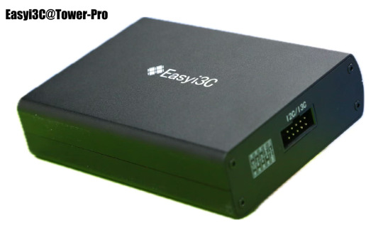
【step by step】Easyi3C Host I3C adapter (1)
Easyi3C is a leading supplier of embedded system tools that simplify the development and debugging of various communication protocols. The company offers a range of products designed to help engineers and developers use I3C/I2C , USB and MIPI, JEDEC, MCTP and other protocols more efficiently.
1. Basic Introduction
Easyi3C Host I3C adapter is a powerful and easy-to-use I3C and I2C host adapter produced by Easyi3C. It connects the computer to the downstream embedded system environment through the USB interface and adopts the advanced I3C and I2C protocol.
Based on the application programming interface (API) function and the Easyi3C Tower console graphical user interface (GUI) tool, combined with the Python development environment, the Easyi3C Host adapter greatly simplifies the development process of I3C/I2C chip testing and data transmission environment. It provides great convenience for AE engineers, FAE engineers, etc. to verify I3C/I2C chips. Simple verification can be done through the graphical console interface, which is easy to use and easy to learn. If you want to test more complex functions or perform automated testing, you can use the rich API functions provided by the manufacturer to quickly implement automated scripts in the Python development environment.
We know that I2C was invented by Philips Semiconductors in 1981, and its history is a bit old and mature. The I3C protocol I3C specification was originally released by in 2017. I3C is the abbreviation of improved internal integrated circuit, which is a 2-wire digital interface similar to I2C. It improves and optimizes the previously released I2C and SPI interfaces, solves the problem of slow I2C communication speed, and optimizes the shortcomings of SPI through four-wire connection. The I3C specification is managed by MIPI Alliance Inc. I3C also solves the problem of high power consumption of I2C. I3C becomes a low-power, low-cost and fast digital interface. It supports multi-point connection between host MCU and peripheral devices such as sensors and multi-master devices. Because the protocol is still very new, there are not many good tools on the market. The series of products launched by Easyi3C will fill this gap. The same interface supports I3C/I2C protocols at the same time, which is convenient for engineers to write automated scripts for chip protocol testing, shorten the product launch cycle, and help the company’s products win the competition.
2. Key features:
Supports MIPI I3C BASIC v1.1 JEDEC JESD403–1 Specifications (JEDEC DDR5 Sideband Bus Spec) I3C Master in SDR mode Variable Working Frequencies (Open-Drain Mode: 1 kHz to 4 MHz (Default: 1MHz); Push-Pull Mode: 100KHz to 12.5 MHz (Default: 4MHz)) Adjustable SCL Duty Cycle Amplitude Variation: 0.8V to 3.3V in steps of 10mV 5ns resolution Supports 7-Bit Slave Addressing Supports Common Command Code (CCC) transactions Supports flexible payload length’s IBI Supports Hot Plug Supports all Dynamic Address Assignments Supports legacy I2C Master, Software configurable I2C pull-up Error Injection such as parity errors USB Type-C port, Max. Current & Voltage: 500 mA @ 5 V Supports online upgrade API support for automation test in Python Physical Size: 114mm x 81mm x 27mm Operating Temperature From –20°C to +85°C
3. Hardware
Accessories:


4. Interface Introduction 4.1 Front Panel


5. Test chip connection method
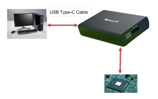
5.1 Connect the Easyi3C adapter to the I2C/I3C device using a 10-pin cable.
5.2 Connect the Easyi3C adapter to the computer with a USB Type-C cable. The adapter is powered by USB Type-C communication, so no separate external power supply is required, which simplifies device connection.
Next, we will continue to introduce the use of the product in depth.
1 note
·
View note
Text
PLC Programming Using CODESYS: An In-Depth Exploration

Programmable Logic Controllers (PLCs) are foundational to industrial automation, providing the control necessary for machinery and processes across various industries. Among the myriad of PLC programming environments available, CODESYS stands out as a versatile and powerful platform. This article delves into the intricacies of PLC programming using CODESYS, its adherence to the IEC 61131-3 standard, fieldbus support, IoT connectivity, and the services offered by Servotech Inc. in this domain.
Understanding CODESYS
CODESYS is a commercial PLC programming tool and real-time software platform designed for PLCs and embedded controllers. It offers a comprehensive suite of features that facilitate the development, testing, and deployment of control applications. One of its notable strengths is its manufacturer-independent nature, allowing engineers to program controllers from various vendors using a unified interface.
Adherence to IEC 61131-3 Standard
The IEC 61131-3 standard defines the programming languages and structures for PLCs, promoting consistency and interoperability across different systems. CODESYS supports all five languages outlined in this standard:
Instruction List (IL): An assembler-like language for low-level programming.
Structured Text (ST): A high-level, Pascal-like language suitable for complex algorithms.
Ladder Diagram (LD): A graphical language resembling electrical relay logic diagrams, widely used for its intuitive representation.
Function Block Diagram (FBD): A graphical language that uses blocks to represent functions and their interconnections.
Sequential Function Chart (SFC): A graphical language for depicting sequential control processes.
By adhering to this standard, CODESYS ensures that engineers can transition between different PLC hardware platforms without the need to learn new programming environments, thereby enhancing efficiency and reducing training costs.
Fieldbus Support in CODESYS
Fieldbus systems are critical for enabling communication between various components in an industrial setup. CODESYS provides extensive support for multiple fieldbus protocols, including:
EtherCAT: A high-performance Ethernet-based fieldbus system suitable for real-time control applications.
CAN Bus (CANopen, J1939): Widely used in automotive and industrial applications for robust communication.
Modbus: A serial communication protocol prevalent in connecting industrial electronic devices.
PROFIBUS: A standard for fieldbus communication in automation technology.
This extensive fieldbus support allows for seamless integration of various devices and systems, facilitating the development of complex automation solutions.
IoT Connectivity with CODESYS
In the era of Industry 4.0, the integration of IoT (Internet of Things) capabilities into industrial automation systems is paramount. CODESYS offers robust IoT connectivity features, enabling:
Remote Monitoring and Control: Access and control PLCs from remote locations, enhancing flexibility and responsiveness.
Data Logging and Analysis: Collect and analyze data from various sensors and devices to optimize processes and predict maintenance needs.
Cloud Integration: Seamlessly connect with cloud platforms for data storage, processing, and advanced analytics.
These IoT capabilities empower industries to implement smart manufacturing practices, leading to increased efficiency and reduced operational costs.
Servotech Inc.: Expertise in CODESYS PLC Programming
Servotech Inc. is a leading provider of PLC programming services utilizing the CODESYS platform. Their team of experienced engineers offers comprehensive solutions, including:
Custom PLC Application Development: Tailored solutions to meet specific automation requirements across various industries.
System Integration: Seamless integration of PLCs with existing hardware and software systems, ensuring optimal performance.
Training and Support: Providing clients with the knowledge and tools necessary to maintain and expand their automation systems effectively.
By leveraging CODESYS's versatile platform, Servotech Inc. delivers robust and scalable automation solutions that adhere to international standards.
Conclusion
PLC programming by Servotechinc using CODESYS offers a flexible and standardized approach to industrial automation. Its compliance with the IEC 61131-3 standard, extensive fieldbus support, and IoT connectivity make it a preferred choice for engineers and organizations aiming to develop sophisticated control systems. Servotech Inc.'s expertise in utilizing CODESYS further enhances the potential for creating customized, efficient, and future-ready automation solutions
#PLCProgramming#IndustrialAutomation#CODESYS#AutomationEngineering#SmartManufacturing#EmbeddedSystems#IndustrialControl#FactoryAutomation#IoTIntegration#ControlSystems
0 notes
Text
Demystifying SAN Solution Architecture
Efficient, reliable, and scalable data management has become the backbone of modern IT infrastructure, and for good reason. Enterprises require robust solutions to handle exponential data growth, reduce latency, ensure availability, and maintain secure backup systems within their data centers. This is where Storage Area Network (SAN) architecture comes into play.
Whether you're an IT professional building a data center from the ground up or a data center manager optimizing system performance, understanding SAN design and implementation is crucial. This blog will explore SAN architecture, its key components, types of design, and practical considerations to help you deploy or enhance an effective SAN system.
What Is SAN Architecture?
A Storage Area Network (SAN) is a high-speed, specialized network connecting servers to storage devices. Instead of traditional storage architectures where data travels through LAN or WAN connections, a SAN enables direct block-level data access by bypassing general-purpose networks. This results in significantly higher performance and reduced bottlenecks.
At its core, a SAN provides centralized storage pools that are accessible to multiple servers, delivering exceptional scalability, redundancy, and efficient data management for critical enterprise workflows.
Why SAN Matters in Modern IT Environments
SANs are essential for organizations dealing with:
Large databases or business-critical applications, e.g., ERP or CRM systems that require ultra-low latency.
Virtualization environments, where numerous virtual machines (VMs) demand shared storage infrastructure for seamless performance.
Data-intensive industries such as banking, healthcare, or media, requiring secure, fast, and scalable storage systems.
From disaster recovery to 24/7 access, SAN architecture addresses storage reliability and performance challenges head-on.
Key Components of SAN Architecture
To truly understand SAN architecture, it's important to know its essential building blocks. Each component of this ecosystem plays an integral role in delivering an effective and efficient SAN setup.
1. Storage Arrays
Also known as storage subsystems, these are the physical or virtual storage devices that hold all the organization’s critical data. SAN typically leverages multiple arrays to provide redundancy and support various RAID configurations (e.g., striping, mirroring, parity).
Types of Storage Arrays:
Hard Disk Drives (HDDs) for high capacities at lower costs per GB.
Solid-State Drives (SSDs) for high-speed, low-latency storage use cases.
Hybrid Solutions combining HDDs and SSDs for balanced performance and cost savings.
2. SAN Switches
SAN switches enable connectivity between storage arrays and servers. They create fabric networks for reliable, low-latency communication.
Benefits of SAN Switches:
Scalability through fabric extension.
Zoning capabilities to isolate traffic between specific devices for increased security.
Fault tolerance through multi-pathing.
Popular SAN switch manufacturers include Brocade, Cisco, and Juniper Networks.
3. Host Bus Adapters (HBAs)
Host Bus Adapters act as an interface between servers and storage devices. HBAs handle protocols such as Fibre Channel (FC), iSCSI, or FCoE (Fibre Channel over Ethernet) to ensure seamless transmission of data.
Key Features:
Offloading tasks like error correction to reduce CPU strain.
Enhanced throughput for faster data transfer rates.
4. Fibre Channel or Ethernet Fabrics
SANs rely on high-speed interconnects. Fibre Channel (FC) has long dominated SAN environments thanks to its incredible speeds and reliability. However, Ethernet-based solutions like iSCSI and FCoE are often leveraged in smaller setups.
Fibre Channel Advantages:
Speeds over 128 Gbps with low latency.
Dedicated protocol for SAN traffic, ensuring robust performance.
iSCSI Advantages:
Cost-efficient, as it uses existing Ethernet infrastructure.
Easier integration into hybrid networks.
Designing a SAN Architecture: Types and Best Practices
Developing a SAN system involves tailoring the design based on specific organizational needs. Here are the primary types of SAN design:
Type 1: Monolithic Storage Architecture
Monolithic SAN designs feature centralized enterprise storage systems, typically used in large-scale enterprises with extensive performance and redundancy requirements.
Advantages:
High throughput and fault tolerance.
Ideal for high-performance environments.
Use Case:
Global corporations managing enterprise resource planning (ERP) workflows.
Type 2: Modular Storage Architecture
Modular SANs are a flexible alternative, built with individual components that can be added or removed as needed.
Advantages:
Highly scalable for growing enterprises.
Cost-effective in smaller stages.
Use Case:
Small to mid-sized businesses seeking scalable storage without excessive upfront costs.
Type 3: Hyper-Converged Infrastructure (HCI) SAN
Hyper-converged SANs combine compute, networking, and storage resources into a single solution, often leveraging virtual storage appliances (VSAs).
Advantages:
Simplified management through a centralized dashboard.
Cost-effective for cloud or virtualized workloads.
Use Case:
Enterprises scaling up their virtual private cloud (VPC) environments.
Best Practices for SAN Deployment
Understand Your Workload: Leverage tools like IOPS calculation and bandwidth assessments before building your SAN.
Choose the Right Protocol: Match protocols (e.g., iSCSI for small deployments or FC for low-latency enterprise needs) to your specific requirements.
Implement Zoning: Use zoning in switches to intelligently isolate traffic between storage and host devices, enhancing both performance and security.
Build for Redundancy: Add multiple paths, switches, and HBAs to eliminate single points of failure.
Regular Monitoring & Maintenance: Continuously monitor performance metrics (throughput, latency) using tools like SANtricity or NetApp OnCommand.
Practical Applications of SAN
1. High-Performance Applications
Businesses running applications such as Microsoft SQL Server or Oracle Databases rely on SANs for reduced query times and improved availability.
2. Virtualized Data Centers
SAN architecture supports VMware, Hyper-V, or similar platforms to provide shared storage pools for VMs, ensuring seamless provisioning and high levels of fault tolerance.
3. Disaster Recovery
Replication technologies, such as synchronous or asynchronous mirroring, enable SANs to play an integral role in disaster recovery strategies, ensuring data redundancy across multiple locations.
4. Content Creation and Media
Video editing, 3D rendering, and CGI workflows depend on high-speed, low-latency SAN solutions to manage massive data transfers.
Transforming Data Centers with Enterprise SANs
SAN architecture continues to evolve, blending innovation with scalability. From hybrid SAN designs combining on-premise and cloud storage to software-defined storage arrays modernizing traditional infrastructure, SANs are essential for enterprise success.
Investing in SAN solutions isn’t just about addressing current storage demands—it’s a strategic move to future-proof your data center.
Optimizing or Deploying Your SAN Ecosystem?
If your business is exploring SAN implementations or upgrading existing storage architecture, take the next step confidently. Contact our team for tailored solutions customized to drive efficiency and performance in your IT ecosystem.
0 notes
Text
Top 8 Cybersecurity Skills You Must Have

Cybersecurity is a critical and rapidly evolving field with a high demand for skilled professionals. To succeed in this dynamic domain, you'll need a strong foundation of technical skills and a proactive approach to continuous learning. Here are the top 8 cybersecurity skills you must have:
1. Networking Fundamentals:
TCP/IP Model: A deep understanding of the TCP/IP model, the foundation of modern computer networking, is crucial. This includes knowledge of protocols like TCP, UDP, IP, and how data flows across networks.
Network Devices: Familiarity with network devices such as routers, switches, firewalls, and their functions within a network infrastructure.
Network Topologies: Understanding different network topologies, including star, bus, ring, and mesh, and their implications for security.
Network Troubleshooting: Ability to diagnose and troubleshoot network connectivity issues, identify performance bottlenecks, and analyze network traffic.
2. Operating System Principles:
Windows: In-depth knowledge of Windows operating systems, including user management, file system permissions, security policies, and common vulnerabilities.
Linux: Proficiency in Linux operating systems, including command-line interface, system administration, and security best practices.
macOS: Understanding of macOS security features and how to configure and maintain a secure macOS environment.
3. Programming and Scripting:
Python: A versatile language widely used in cybersecurity for tasks such as vulnerability scanning, malware analysis, and automation.
Scripting Languages: Proficiency in scripting languages like Bash and PowerShell for automating tasks, analyzing logs, and interacting with systems.
Other Languages: Familiarity with languages like C/C++ can be beneficial for advanced security research and exploit development.
4. Cryptography:
Encryption Algorithms: Understanding of various encryption algorithms, including symmetric-key encryption (AES, DES), asymmetric-key encryption (RSA, DSA), and hashing algorithms (SHA-1, SHA-256).
Digital Signatures: Knowledge of digital signatures, their use in authentication and data integrity, and how they are implemented.
Cryptography Concepts: Understanding of cryptographic concepts such as key exchange, public-key infrastructure (PKI), and certificate authorities.
5. Incident Response:
Incident Handling Lifecycle: Familiarity with the incident response lifecycle, including identification, containment, eradication, recovery, and lessons learned.
Forensics Techniques: Basic understanding of digital forensics techniques for collecting, preserving, and analyzing evidence from computers and networks.
Incident Reporting: Ability to document and report security incidents effectively and concisely.
6. Threat Intelligence Analysis:
Threat Intelligence Gathering: Ability to gather threat intelligence from various sources, including threat feeds, security advisories, and open-source intelligence.
Threat Analysis: Analyzing threat intelligence to identify potential threats, assess their impact, and develop appropriate mitigation strategies.
Threat Hunting: Proactively searching for and identifying threats within an organization's systems and networks.
7. Risk Assessment and Management:
Vulnerability Assessment: Identifying and assessing vulnerabilities in systems, networks, and applications.
Threat Modeling: Identifying and analyzing potential threats to an organization's systems and data.
Risk Management Frameworks: Understanding and applying risk management frameworks, such as NIST Cybersecurity Framework, to develop and implement security controls.
8. Communication and Collaboration:
Effective Communication: Ability to clearly and concisely communicate technical information to both technical and non-technical audiences, including management, executives, and legal teams.
Teamwork and Collaboration: Ability to work effectively in a team environment, collaborate with other security professionals, and contribute to a strong security culture within an organization.
Building These Skills:
Formal Education: A degree in computer science, cybersecurity, or a related field provides a strong foundation.
Hands-on Experience: Gain practical experience through internships, personal projects, and participating in Capture The Flag (CTF) competitions.
Certifications: Obtain industry-recognized certifications such as CompTIA Security+, Certified Ethical Hacker (CEH), and Certified Information Systems Security Professional 1 (CISSP) to enhance your credentials and career prospects.
Continuous Learning: Cybersecurity is a constantly evolving field. Stay updated on the latest threats, vulnerabilities, and technologies through online courses, industry publications, and conferences.
To accelerate your learning and gain a comprehensive understanding of cybersecurity concepts, consider exploring programs like Xaltius Academy's Cybersecurity course. This comprehensive program can provide you with the necessary knowledge, skills, and guidance to navigate the challenges and build a rewarding career in this dynamic and critical field.
0 notes
Text
Mapping Hardware to Software: Understanding Devicetrees
We learned how to enable and disable particular Zephyr subsystems using the "Kconfig" infrastructure in the previous blog post, "Getting Started With Zephyr: Kconfig." In particular, we looked at the Kconfig infrastructure's three primary components. To enable the LED subsystem, we first looked at an example of a Kconfig file and how the Kconfig infrastructure is constructed. Second, we observed how the Nordic VS Code Extension's GUI-based Kconfig interface can be used to enable or disable particular Zephyr subsystems. Lastly, we observed a way to modify Zephyr that can be integrated into systems that rely on CI/CD.
Adding support for communication buses and peripherals is a standard step in embedded software development, in addition to modifying an RTOS to enable or disable particular subsystems. Other MCU vendors integrate customization features into their IDE, such as enabling communication buses and configuring their parameters, as was discussed in the previous blog post. However, Zephyr also uses the "Devicetree," another construct from the Linux kernel (keep in mind that Kconfig also comes from the Linux kernel). Devicetree, or DT for short, is a data structure that describes hardware using its own language.
As ARM-based System-on-Chips (SoCs) and System-on-Modules (SoMs) running embedded Linux gained popularity, so did Devicetrees in embedded software. Bus designs that enabled automatically identifying the hardware connected to the CPU were used when Linux was first developed on Intel-based CPUs. The hardware did not need to be described in advance. However, new communication protocols and buses without any detection mechanism were introduced when ARM exploded onto the scene. As a result, the Linux kernel required a tool to recognize these buses and the devices they were connected to. Though Zephyr borrowed the devicetree concept from the Linux kernel, it is important to remember that Zephyr's use of the devicetree differs sufficiently from the Linux kernel.
BASIC SYNTAX
One of the most crucial things to keep in mind about the devicetree—which typically causes anxiety for embedded software engineers who are not familiar with Linux—is that it is neither magical nor enigmatic. All it is is a file with a vague structure. Each node in the file contains a specific set of definitions. Other nodes can include and reference a node. For instance, the LEDs found on a Nordic nRF52840 development kit are described in the following excerpt.
(https://www.nordicsemi.com/Products/Development-hardware/nrf52840-dk): leds { compatible = "gpio-leds"; led0: led_0 { gpios = <&gpio0 13 GPIO_ACTIVE_LOW>; label = "Green LED 0"; }; led1: led_1 { gpios = <&gpio0 14 GPIO_ACTIVE_LOW>; label = "Green LED 1"; }; led2: led_2 { gpios = <&gpio0 15 GPIO_ACTIVE_LOW>; label = "Green LED 2"; }; led3: led_3 { gpios = <&gpio0 16 GPIO_ACTIVE_LOW>; label = "Green LED 3"; };};
The "leds" node describes the four LEDs onboard the development kit.
As an aside, if you have experience with Linux, you will be familiar with the aforementioned "compatible" property. To control the GPIOs, Zephyr "finds" a device driver with a corresponding "compatible" value and calls the functions listed in the device driver. This is what you might assume right away, as I did. This isn't right! We will go into greater detail in the upcoming blog post about Zephyr's "bindings," which are its own methods for linking devicetree entries to source code. For the time being, it is important to keep in mind that Zephyr and Linux use devicetrees in sufficiently different ways.
Going back to our example, the four LEDs that the "leds" node mentions also mention nodes! For instance, in the line that follows, the "led0" node indicates the precise GPIO that is utilized to control that specific LED: led0: led_0 { gpios = <&gpio0 13 GPIO_ACTIVE_LOW>; label = “Green LED 0”;}
In the above example, GPIO0_13 controls LED0 on the board, an active low GPIO. This node consists of the following elements:
"led0" is the "node label", and is used to reference the Devicetree node.
“led_0” is the node's "full name." Typically, a node's full name consists of the node name and a unit address (for example, "my-node@12345678"), but a node without an address is acceptable as well (sometimes an address doesn't make sense, as is the case here).
·“gpios” is an example of a "property" of the "led0" node. A property is ultimately used by source code to control hardware in some manner. In this instance, the "gpios" property defines a GPIO port, pin, and the active state. The device driver uses this information to control the GPIO.
·“label” is also a property of the "led0" node. Specifically, the label property can retrieve a more descriptive name for a node. In this example, "Green LED 0" can reference the node instead of "led0".
DEVICETREE LOCATION AND HIERARCHY
An illustration of a devicetree node for the Nordic nRF52840 development kit's LEDs was shown in the section above. Looking through the various devicetrees in the Zephyr repository can be useful (we will see why in a future blog post). The Zephyr repository contains the devicetrees in two main locations. The "boards" directory in the corresponding processor architecture directory contains the devicetrees for the many boards that Zephyr supports. The top-level devicetree for the nRF52840 development kit, for instance, can be found under "boards/arm/nrf52840dk_nrf52840":
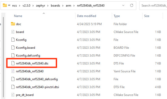
".dts" is the extension for the "top-level" devicetree file, and ".dtsi" is the extension for intermediate devicetree files that are referenced by the top-level devicetree. It is possible for intermediate devicetree files to contain other intermediate files. The node that represents the LEDs on the board is visible in the nRF52840 development kit's top-level devicetree file, "nrf52840dk_nrf52840.dts," when we open it in the example above!

If we scroll to the top of this file, we see the following statements: /dts-v1/;#include <nordic/nrf52840_qiaa.dtsi>#include "nrf52840dk_nrf52840-pinctrl.dtsi"
We discovered how to incorporate support for custom hardware into our Zephyr-based firmware using the "Devicetree" in this blog post. We learned how to describe LEDs on a board and specify the corresponding GPIOs from a "blinky" example. Additionally, we discovered where devicetree files are located within the Zephyr repository and how their arrangement enables the description of boards, beginning with the CPU.
Utilizing device drivers created by others is one of the biggest benefits of using devicetree files in Zephyr over other mechanisms provided by MCU vendors in their IDEs. Usually, we have to write driver code from scratch or import libraries in various MCU-specific environments and IDEs. Instead, we can take advantage of other people's work by using Zephyr's devicetrees and device driver model. We can concentrate on crafting our final application's business logic. We will examine Zephyr's internal workings in the upcoming blog post to learn how it uses devicetrees and how it varies from the Linux kernel.
Ready to integrate your custom hardware into Zephyr-based firmware efficiently? At Silicon Signals, we excel in embedded systems development, offering expertise in hardware design, firmware development, and system optimization. Leverage our capabilities to streamline your projects, utilizing tools like Zephyr's devicetrees and driver models to focus on what truly matters—your application's core functionality.
👉 Get in Touch to explore how we can help you accelerate your embedded solutions!
1 note
·
View note
Text
Future Trends in In Vehicle Networks: Advancements and Innovations
The future of in-vehicle networks is shaped by technological advancements, consumer demand for connected services, and regulatory requirements for vehicle safety and cybersecurity. This article explores emerging trends, innovations, and the transformative potential of in-vehicle networks in shaping the future of automotive technology.
Evolution of In Vehicle Networks
From CAN Bus to Ethernet: In-vehicle networks evolve from traditional CAN Bus and LIN protocols to high-speed Ethernet and FlexRay architectures. Ethernet supports bandwidth-intensive applications, such as multimedia streaming, autonomous driving systems, and vehicle-to-everything (V2X) communication.
Integration with IoT Devices: In Vehicle networks integrate with Internet of Things (IoT) devices, smart sensors, and connected infrastructure to enhance vehicle connectivity, gather real-time data, and optimize operational efficiency. IoT integration supports predictive maintenance, traffic management, and personalized driving experiences.
Emerging Technologies and Innovations
5G Connectivity: The deployment of 5G networks accelerates in-vehicle communication speeds, reduces latency, and supports ultra-reliable low-latency communication (URLLC) for safety-critical applications. 5G integration enhances V2X communication, improves traffic flow, and enables seamless vehicle connectivity.
Edge Computing: Edge computing platforms process data locally within in-vehicle networks, reducing latency, optimizing bandwidth usage, and supporting real-time decision-making for autonomous driving and cloud-based applications. Edge computing enhances in-vehicle network performance and responsiveness.
Automotive Cybersecurity and Data Privacy
Secure OTA Updates: Automotive manufacturers implement secure OTA update mechanisms to deploy software patches, firmware upgrades, and security enhancements remotely. Secure OTA ensures data integrity, verifies update authenticity, and protects in-vehicle networks against cyber threats.
Regulatory Compliance: Compliance with automotive safety standards, such as ISO 26262 for functional safety and UN ECE regulations for cybersecurity, ensures vehicle safety and regulatory adherence. Manufacturers integrate cybersecurity measures into in-vehicle networks to protect against cyber threats and ensure consumer trust.
Consumer Demand and User Experiences
Connected Services: Consumer demand for connected services drives the adoption of in-vehicle networks that support advanced features, such as real-time navigation updates, voice-controlled assistants, and personalized infotainment options. Connected services enhance driver convenience, entertainment, and overall vehicle usability.
User-Centric Design: Automotive OEMs prioritize user-centric design principles to enhance the usability and accessibility of in-vehicle networks. Intuitive interfaces, seamless connectivity with mobile devices, and personalized settings improve driver satisfaction and foster brand loyalty.
Future Innovations and Industry Collaboration
AI-Powered Analytics: Integration of artificial intelligence (AI) and machine learning (ML) enables predictive analytics for in vehicle networks. AI algorithms analyze vehicle data, predict maintenance needs, optimize energy efficiency, and enhance driver safety through real-time insights and proactive recommendations.
Smart City Integration: In-vehicle networks contribute to smart city initiatives by supporting traffic management systems, environmental monitoring, and urban mobility solutions. Vehicle-to-infrastructure (V2I) communication enhances traffic flow, reduces emissions, and improves overall transportation efficiency.
Conclusion
Future trends in in-vehicle networks are driven by technological advancements, regulatory requirements, and evolving consumer preferences for connected services and enhanced driving experiences. By embracing innovations in connectivity, cybersecurity, and user-centric design, automotive stakeholders shape the future of mobility, redefine industry standards, and accelerate the adoption of next-generation in-vehicle networks.
0 notes
Text
DakoBus: Committed to Safe and Reliable Passenger Transport
In today’s fast-paced world, the demand for safe and reliable transportation is more critical than ever. DakoBus has established itself as a leader in the passenger transport industry, unwavering in its commitment to providing safe, dependable, and efficient services. With over 25 years of experience, DakoBus is dedicated to ensuring that every journey is a positive experience for its passengers.
Safety First At DakoBus, safety is not just a priority; it is a core value. The company takes a transfer rome airport comprehensive approach to safety, implementing rigorous protocols and standards. Each bus in the fleet undergoes thorough inspections and maintenance to ensure optimal performance. Advanced safety features—such as GPS tracking, anti-lock braking systems, and real-time monitoring—are standard in all vehicles, allowing for enhanced safety during travel.
DakoBus also invests in the training and development of its drivers. Each driver undergoes extensive training not only in safe driving practices but also in customer service, ensuring that passengers feel secure and valued throughout their journey.
Reliability You Can Count On Reliability is a hallmark of DakoBus service. With meticulously planned routes and schedules, DakoBus ensures timely arrivals and departures. Passengers can trust that their transportation will be consistent and punctual, whether they are commuting to work, attending school, or heading to a special event.
DakoBus employs modern technology to enhance operational efficiency. Real-time tracking systems allow passengers to monitor their bus locations and receive updates on arrival times, reducing uncertainty and enhancing the overall travel experience. This commitment to reliability ensures that DakoBus remains a trusted partner for daily commuters and occasional travelers alike.
Focus on Comfort and Convenience DakoBus understands that comfort is essential for a pleasant travel experience. The fleet is designed with passenger comfort in mind, featuring spacious seating, climate control, and clean, well-maintained interiors. On select routes, amenities such as Wi-Fi are available, allowing passengers to stay connected while on the move.
Convenience is also a key focus. The DakoBus mobile app offers a user-friendly interface for passengers to access schedules, track buses in real-time, and receive notifications about service changes. This technological integration empowers passengers, making their travel experience seamless and enjoyable.
Community Engagement and Environmental Responsibility DakoBus believes in giving back to the communities it serves. The company actively engages with local organizations and participates in initiatives that promote public transport and community welfare. By fostering strong community ties, DakoBus reinforces its role as a responsible corporate citizen.
Additionally, DakoBus is committed to environmental sustainability. The introduction of hybrid and electric buses into the fleet reflects the company’s dedication to reducing its carbon footprint. By prioritizing eco-friendly transportation solutions, DakoBus contributes to cleaner air and a healthier environment for future generations.
Looking Ahead As DakoBus continues to grow and adapt to the changing landscape of passenger transport, its focus on safety, reliability, and customer satisfaction remains steadfast. Plans for expanding services and enhancing technology will further solidify DakoBus’s position as an industry leader.
In summary, DakoBus is more than just a transportation provider; it is a dedicated partner in safe and reliable passenger transport. With a strong commitment to safety, comfort, and community engagement, DakoBus is poised to deliver exceptional service for years to come, ensuring that every journey is not just a ride, but a secure and enjoyable experience.
1 note
·
View note
Text
PCIe Faster than PCI?
PCIe: A Leap Forward from PCI
The Peripheral Component Interconnect (PCI) standard has played a crucial role in the evolution of computer architecture since its introduction in the early 1990s. However, as technology advanced and the demand for higher data transfer rates and better bandwidth management increased, PCI was eventually succeeded by the more robust Peripheral Component Interconnect Express (PCIe) standard. This article explores the differences between PCI and PCIe, emphasizing the role of the card edge connector in this transition and why PCIe is significantly faster than its predecessor.
Understanding PCI and PCIe
PCI (Peripheral Component Interconnect) is a parallel interface standard that allows multiple hardware devices, such as graphics cards, sound cards, and network cards, to connect to a computer's motherboard. It operates on a shared bus architecture, meaning that all devices share the same data lines. This architecture limits the amount of data that can be transmitted simultaneously, leading to potential bottlenecks, especially as the number of devices increases.
In contrast, PCIe (Peripheral Component Interconnect Express) employs a serial communication protocol. Instead of sharing a single bus, PCIe establishes point-to-point connections between the motherboard and each device, allowing for dedicated communication channels. This fundamental shift in architecture is one of the primary reasons PCIe can achieve much higher speeds than PCI.
Speed and Bandwidth
When comparing PCI and PCIe, speed and bandwidth are the most significant differentiators. PCI operates at a maximum bandwidth of 133 MB/s per lane, with configurations typically using 32 or 64 bits. In contrast, PCIe operates with lanes that can handle 250 MB/s per lane in each direction for PCIe 1.0. The bandwidth increases significantly with each subsequent version of PCIe:
PCIe 1.0: 2.5 GT/s (Giga-transfers per second) per lane, resulting in 250 MB/s per lane.
PCIe 2.0: 5 GT/s per lane, doubling the bandwidth to 500 MB/s.
PCIe 3.0: 8 GT/s per lane, achieving roughly 1 GB/s per lane.
PCIe 4.0: 16 GT/s per lane, reaching approximately 2 GB/s.
PCIe 5.0: 32 GT/s per lane, achieving around 4 GB/s.
PCIe 6.0: The latest iteration, projected to reach 64 GT/s per lane, will allow for a theoretical maximum of 8 GB/s per lane.
This exponential growth in data throughput makes PCIe vastly superior to PCI, enabling modern applications such as high-performance gaming, data-intensive workloads, and real-time processing.
The Role of the Card Edge Connector
One of the critical components of both PCI and PCIe is the card edge connector. This connector serves as the interface between the expansion card and the motherboard, allowing for electrical and mechanical connections. The design and configuration of the card edge connector differ significantly between PCI and PCIe, impacting performance and compatibility.
Connector Design:
PCI Connectors: PCI cards typically feature a 120-pin connector that aligns with the 32-bit or 64-bit data bus. The design allows for a relatively straightforward connection but can limit performance due to the shared bandwidth.
PCIe Connectors: PCIe connectors come in various configurations, including x1, x4, x8, and x16. Each configuration corresponds to the number of lanes available for data transmission. For example, an x16 connector has 16 lanes, allowing for significantly higher bandwidth. The card edge connector for PCIe is more complex, with a greater number of pins (up to 164 for x16) to accommodate the increased data transmission capabilities.
Mechanical Features:
PCIe connectors are designed with a more robust mechanical structure, ensuring secure connections and better alignment. This improved design helps mitigate issues related to signal integrity, which can arise in high-speed data transmission.
Power Delivery:
PCIe connectors also provide enhanced power delivery options. While PCI typically delivers power through the motherboard, PCIe cards can draw additional power directly from the connector, allowing for more demanding devices, such as high-end graphics cards, to operate efficiently.
Advantages of PCIe Over PCI
The advantages of PCIe over PCI extend beyond speed and bandwidth. Here are some key benefits that PCIe offers:
Scalability:
PCIe's architecture allows for greater scalability. As technology evolves and new devices require more bandwidth, PCIe can accommodate these demands without significant redesigns. New versions of PCIe can be deployed without altering the physical connector, ensuring backward compatibility with older devices.
Reduced Latency:
The point-to-point connection in PCIe reduces latency compared to the shared bus architecture of PCI. Each device communicates directly with the CPU and memory, leading to faster data transfers and improved overall system performance.
Improved Resource Management:
PCIe’s architecture allows for better resource management, enabling the system to allocate bandwidth dynamically based on the needs of connected devices. This flexibility ensures that high-demand applications receive the resources they require without being hindered by other devices on the bus.
Enhanced Error Handling:
PCIe incorporates advanced error handling mechanisms, including error detection and correction features. This capability enhances data integrity and reliability, critical for applications where data loss or corruption cannot be tolerated.
Support for Multiple Devices:
PCIe's ability to support multiple devices simultaneously, each with its own dedicated bandwidth, is a significant advantage in modern computing environments. This feature is particularly beneficial for gaming, video editing, and data-intensive applications, where multiple high-performance devices may be in use at the same time.
Conclusion
The transition from PCI to PCIe marks a significant evolution in computer architecture. PCIe’s point-to-point architecture, enhanced bandwidth capabilities, improved card edge connector design, and superior resource management make it a far more efficient and powerful interface for modern computing needs. As technology continues to advance, PCIe will undoubtedly play a critical role in supporting the increasing demands for speed and performance in various applications.
In summary, PCIe is not just faster than PCI; it represents a paradigm shift in how devices communicate with the motherboard, paving the way for future innovations in computer technology. As we look ahead, it is clear that the card edge connector will continue to be a vital component in this ongoing evolution, enabling the seamless integration of ever more powerful devices into our computing systems.
1 note
·
View note
Text
FUTURE TRENDS & GROWTH PROSPECT OF IRCTC TOURISM
The future trends and growth prospects of IRCTC Tourism look promising, increasing domestic and international travel demand, and strategic initiatives to enhance customer experience. Here are some key trends and growth prospects:

1. Digital Transformation
Enhanced Online Platforms: Continuous improvement of the IRCTC website and mobile app for a more user-friendly interface, personalized recommendations, and seamless booking experience.
AI and Machine Learning: Greater use of AI and ML for personalized travel packages, dynamic pricing, and predictive analytics to forecast travel trends and demand.
2. Sustainable Tourism
Eco-Friendly Practices: Increased focus on sustainable tourism practices, such as promoting eco-tourism, reducing carbon footprints, and implementing green energy solutions at facilities.
Responsible Tourism: Initiatives to promote responsible tourism, including community-based tourism, conservation efforts, and support for local economies.
3. Luxury and Niche Travel
Luxury Train Services: Expansion of luxury train services like the Maharajas' Express and Palace on Wheels, targeting high-end tourists seeking unique travel experiences.
Themed Tours: Growth of niche tourism segments such as wellness tourism, culinary tours, adventure travel, and cultural heritage tours.
4. Technological Innovations
Virtual Reality (VR) and Augmented Reality (AR): Use of VR and AR for virtual tours and immersive travel experiences, helping customers explore destinations before booking.
Blockchain Technology: Exploration of blockchain for secure and transparent transactions, loyalty programs, and digital identity verification.
5. Expanded Services
Integrated Travel Solutions: Offering comprehensive travel solutions that include multi-modal transport options (train, flight, bus) and seamless integration with hotels, car rentals, and local tours.
Cruise Tourism: Development of more river and ocean cruise packages to tap into the growing demand for cruise travel.
6. Customer-Centric Approaches
24/7 Customer Support: Enhanced customer support services, including AI-powered chatbots and multilingual support, to cater to a diverse customer base.
Customized Packages: Offering more customized and flexible travel packages to meet the specific needs and preferences of different traveler segments.
7. Market Expansion
International Tourism: Targeting international markets by promoting Indian tourism globally and offering tailored packages for foreign tourists.
Domestic Tourism: Encouraging domestic travel with attractive packages for lesser-known destinations, promoting regional tourism.
8. Health and Safety
Enhanced Hygiene Protocols: Continued focus on health and safety measures in response to the COVID-19 pandemic, ensuring safe travel experiences for customers.
Travel Insurance: Offering comprehensive travel insurance options to cover health, trip cancellations, and other contingencies.
9. Partnerships and Collaborations
Public-Private Partnerships: Collaborating with private players, state tourism boards, and international tourism organizations to enhance service offerings and expand reach.
Local Collaborations: Partnering with local businesses, artisans, and tour operators to provide authentic and enriched travel experiences.
10. Infrastructure Development
Modernized Facilities: Upgrading and modernizing tourist facilities, railway stations, and accommodation options to meet global standards.
High-Speed Rail: Development of high-speed rail corridors to reduce travel time and improve connectivity between major tourist destinations.
11. Promotional Strategies
Digital Marketing: Leveraging digital marketing strategies, including social media campaigns, influencer partnerships, and online advertising, to attract more travelers.
Travel Expos and Roadshows: Participating in international travel expos and conducting roadshows to promote IRCTC tourism packages and services.
12. Data-Driven Decisions
Big Data Analytics: Utilizing big data analytics to gain insights into customer behavior, preferences, and market trends, enabling informed decision-making and strategy formulation.
Feedback Mechanisms: Implementing robust feedback mechanisms to gather customer reviews and suggestions for continuous improvement.
By embracing these trends and leveraging its strengths, IRCTC Tourism is well-positioned to grow and thrive in the evolving travel and tourism industry.
FOR Services Contact Us now:-
Mobile: - +91 9711090237
E-mail:- [email protected]
#api integration#indian railway tourism#irctc tourism#travel portal solutions#travel portal development#IRCTC TOURISM API INTEGRATION
0 notes
Text
What are the common communication protocols in embedded systems?
Embedded systems are specialized computing systems that perform dedicated functions within larger systems. They are integral to various industries, including automotive, medical, consumer electronics, and industrial automation. Communication protocols are essential in embedded systems as they define the rules for data exchange between devices and components, ensuring efficient and reliable operation.
1. Overview of Communication Protocols
Communication protocols are sets of rules that govern data transmission between devices. In embedded systems, these protocols can be broadly categorized into serial, parallel, wired, and wireless types. Choosing the right protocol is crucial for optimizing performance, power consumption, and reliability.
2. Serial Communication Protocols
UART (Universal Asynchronous Receiver/Transmitter)
UART is a widely used serial communication protocol that transmits data asynchronously, meaning there is no clock signal to synchronize data transmission. It's simple and cost-effective, making it ideal for low-speed, short-distance communication. However, its asynchronous nature can lead to synchronization issues over longer distances.
SPI (Serial Peripheral Interface)
SPI is a synchronous serial communication protocol that operates with a master-slave architecture. It uses separate lines for data, clock, and control signals, allowing high-speed data transfer. SPI is commonly used in applications requiring fast communication, such as sensors and memory devices. The downside is the need for multiple lines, which can complicate wiring.
I2C (Inter-Integrated Circuit)
I2C is another synchronous serial communication protocol designed for communication between integrated circuits. It uses two lines (SDA for data and SCL for clock) to connect multiple devices. I2C is efficient for low-speed communication over short distances and supports multiple masters and slaves. However, its slower speed compared to SPI can be a limitation in high-speed applications.
3. Parallel Communication Protocols
IEEE 1284 (Parallel Port)
IEEE 1284 is a parallel communication standard used primarily in older computer systems for connecting peripherals like printers. It can transfer multiple bits of data simultaneously, offering higher data rates than serial communication. However, parallel communication requires more lines, increasing the complexity and cost of the wiring.
GPIB (General Purpose Interface Bus)
GPIB is a parallel communication protocol used in test and measurement equipment. It supports multiple devices on a single bus, providing high-speed data transfer and robust control. GPIB's main drawback is its complexity and the cost associated with its implementation.
4. Wireless Communication Protocols
Wi-Fi
Wi-Fi is a ubiquitous wireless communication protocol used in embedded systems for high-speed, long-range data transfer. It supports a wide range of applications, from consumer electronics to industrial automation. However, Wi-Fi's high power consumption and potential security vulnerabilities can pose significant challenges.
Bluetooth
Bluetooth is a short-range wireless communication protocol ideal for low-power applications such as wearable devices and IoT sensors. It supports data and voice transmission and can connect multiple devices simultaneously. The primary limitations of Bluetooth are its limited range and lower data transfer rates compared to Wi-Fi.
Zigbee
Zigbee is a low-power, low-data-rate wireless communication protocol designed for IoT applications. It supports mesh networking, allowing devices to communicate over extended distances by passing data through intermediate nodes. Zigbee is highly efficient for sensor networks but offers lower data transfer rates.
5. Industrial Communication Protocols
CAN (Controller Area Network)
CAN is a robust serial communication protocol used in automotive and industrial applications. It supports real-time data exchange between multiple devices on a single bus, making it ideal for environments with high noise levels. CAN's main advantages are its reliability and error-handling capabilities, but it has limited data transfer rates.
Modbus
Modbus is a simple and widely adopted serial communication protocol used in industrial automation. It supports master-slave communication and can operate over various physical layers, including RS-232 and RS-485. Modbus is easy to implement and cost-effective, but it may not be suitable for high-speed applications.
PROFINET
PROFINET is an industrial Ethernet standard that provides real-time data exchange and robust performance in industrial automation. It supports high-speed communication and seamless integration with existing Ethernet networks. PROFINET's complexity and cost can be higher than those of traditional serial protocols, but its benefits in performance and scalability often outweigh these drawbacks.
6. Communication Protocols for IoT
MQTT (Message Queuing Telemetry Transport)
MQTT is a lightweight, publish-subscribe messaging protocol designed for low-bandwidth, high-latency networks. It is widely used in IoT applications for reliable, efficient data transfer. MQTT's simplicity and low overhead make it ideal for constrained devices, but it requires a broker to manage message distribution.
CoAP (Constrained Application Protocol)
CoAP is a web transfer protocol optimized for constrained devices and low-power networks. It supports RESTful interactions, making it suitable for IoT applications. CoAP's small footprint and efficient use of resources are its strengths, though it may not offer the same level of robustness as more complex protocols.
LoRaWAN (Long Range Wide Area Network)
LoRaWAN is a long-range, low-power wireless communication protocol designed for IoT networks. It supports large-scale deployments with low data rates, making it ideal for applications like smart cities and agriculture. LoRaWAN's primary advantage is its ability to cover wide areas with minimal power consumption, but it is limited in terms of data throughput.
7. Criteria for Selecting Communication Protocols
When selecting a communication protocol for an embedded system, several factors must be considered:
Data Rate: The speed at which data needs to be transferred.
Distance: the range over which communication must occur.
Power Consumption: The energy efficiency of the protocol.
Reliability: the ability to maintain data integrity and handle errors.
Cost: The overall expense of implementing the protocol.
For example, an embedded software development company might choose SPI for high-speed sensor communication within a device while opting for Zigbee for a low-power, long-range sensor network.
8. Challenges in Implementing Communication Protocols
Implementing communication protocols in embedded systems can present several challenges:
Compatibility Issues: Ensuring different devices and components can communicate seamlessly.
Security Concerns: Protecting data from unauthorized access and tampering.
Power Efficiency: Balancing performance with energy consumption.
Data Integrity: Ensuring reliable data transfer with minimal errors.
Addressing these challenges requires careful planning and robust design practices.
9. Future Trends in Communication Protocols
The future of communication protocols in embedded systems is shaped by advancements in technology and evolving application requirements. Emerging protocols and enhancements to existing ones promise to deliver higher data rates, improved reliability, and greater energy efficiency. Innovations such as 5G and advanced IoT protocols are set to transform the landscape, enabling more sophisticated and interconnected embedded systems.
Conclusion
Choosing the right communication protocol is crucial for the success of embedded systems. Each protocol offers unique advantages and limitations, making it essential to evaluate factors such as data rate, distance, power consumption, reliability, and cost. By understanding the common communication protocols and their applications, developers can design efficient and reliable embedded systems that meet the demands of modern technology.
0 notes