#I2C-Bus
Explore tagged Tumblr posts
Visit Tumblr Blog
Explore Tumblr blogs with no restrictions, modern design and the best experience.
Last Seen Tumblr Blogs


Fun Fact
In 2020, 44% of users from Denmark used Tumblr daily.
Text
https://www.futureelectronics.com/p/semiconductors--comm-products--i2c/pca9532pw-112-nxp-3036484
I2C communication protocol, liquid crystal displays, clock line
PCA9532 Series 5.5 V 350 uA 400kHz SMT 16-bit I2C-bus LED Dimmer - TSSOP-24
#Comm Products#I2C#PCA9532PW#112#NXP#I2C communication protocol#liquid crystal displays#clock line#Bus interface connection protocol#Inter-integrated Circuit#I2C-Bus#I2C circuit diagram#i2c protocol programming#Inter-Integrated Circuit
1 note
·
View note
Text
Ethernet MAC Controller, I2C-bus Repeater, Ethernet Controller
MCP2551 Series 5.5 V 1 Mb/s Surface Mount High-Speed CAN Transceiver - SOIC-8
0 notes
Text
How i2C protocol works....
#mobicationhub #mobicationhub9509959090 #Protocol #reelsfypシ #i2c #institute #phonerepair #mobilerepaircoursejaipur #mobilerepairing #working #1monthcours #laptop
#i2c protocol#i2c protocol tutorial#protocol#spi protocol#communication protocols#i2c protocol vs spi protocol#communication protocol#how i2c protocol works#i2c protocol - inter integrated circuit protocol#i2c communication protocol#i2c protocol working#serial communication protocol#inter integrated circuit protocol#inter-integrated circuit protocol#i2c bus protocol#i3c protocol#what is i2c protocol#basics of i2c protocol#spi protocol tutorial
0 notes
Text
https://www.futureelectronics.com/p/semiconductors--comm-products--i2c/pca9532pw-118-nxp-5033862
16-bit I2C-bus LED Dimmer, Embedded communication, image processing,
PCA9532 Series 5.5 V 350 uA 400kHz SMT 16-bit I2C-bus LED Dimmer - TSSOP-24
#NXP#PCA9532PW#118#Comm Products#I2C#16-bit I2C-bus LED Dimmer#Embedded communication#image processing#High-Speed#Isolated CAN Transceiver ICs#CAN bus lines#i2c modules#Can Power Systems#CAN transceiver#Ethernet MAC controller
1 note
·
View note
Text
https://www.futureelectronics.com/p/semiconductors--comm-products--i2c/pca9515adp-118-nxp-5973557
I2C CAN Bus Module, I2C adapter, I2C devices, Serial Peripheral Interface
PCA9515A Series 3.6 V 5 mA 400 kHz 6 pF Surface Mount I2C-bus Repeater - SOIC-8
#Comm Products I2C#PCA9515ADP#118#NXP#I2C CAN Bus Module#I2C adapter#I2C devices#Serial Peripheral Interface#I2C Level Converter#i2c protocol#spi protocol#uart protocol#i2c communication#i2c protocol in embedded system#I2C-bus Repeater
1 note
·
View note
Text
https://www.futureelectronics.com/p/semiconductors--comm-products--i2c/pca9515adp-118-nxp-7183946
What is I2C communication, serial communication bus, I2C logic
PCA9515A Series 3.6 V 5 mA 400 kHz 6 pF I2C-bus Repeater - SOIC-8
#NXP#PCA9515ADP#118#Comm Products#I2C#What is I2C communication#serial communication bus#I2C logic#Surface Mount I2C bus repeaters#Wire Interface Bus#USB to I2C converter#Encoder motor driver#i2c communication protocol#I2C bus switches
1 note
·
View note
Text
https://www.futureelectronics.com/p/semiconductors--comm-products--i2c/pca9532pw-118-nxp-5033862
I2c bus, Embedded communication, Isolated CAN Transceiver ICs
PCA9532 Series 5.5 V 350 uA 400kHz SMT 16-bit I2C-bus LED Dimmer - TSSOP-24
#NXP#PCA9532PW#118#Comm Products#I2C#Ethernet MAC controller#communication protocol#i2c module#bus#Embedded communication#Isolated CAN Transceiver ICs#High-Speed CAN Transceiver#CAN transceiver#SPI bus#CAN bus lines
1 note
·
View note
Text
https://www.futureelectronics.com/p/semiconductors--comm-products--i2c/pca9515adp-118-nxp-5973557
I2c bus, I2c communication protocol, Inter-Integrated Circuit, spi interface
PCA9515A Series 3.6 V 5 mA 400 kHz 6 pF Surface Mount I2C-bus Repeater - SOIC-8
#Comm Products#I2C#PCA9515ADP#118#NXP#What is I2C communication#High Speed CAN#i2c pins#digital integrated circuits#I2c bus#I2c communication protocol#Inter-Integrated Circuit#spi interface#expanders#I2C bus repeaters
1 note
·
View note
Text
What are I2C devices, I2C in communication, i2c interface, ESD cards
PCA9532 Series 5.5 V 350 uA 400kHz SMT 16-bit I2C-bus LED Dimmer - TSSOP-24
#NXP#PCA9532PW#118#Comm Products#I2C#Surface Mount I2C-bus Repeater#low-speed devices#digital integrated circuits#Inter-Integrated Circuit#multi-controller#i2c pins#what are I2C devices#I2C in communication#i2c interface#ESD cards
1 note
·
View note
Text

The SC16IS74x is an I2C to UART converter
If you know us, you know we luuuuuv I2C as a near-universal interface for sensors, GPIO expanders, OLEDs, and other various devices under our Stemma QT family: https://www.adafruit.com/search?q=stemma+qt 🌱. But we still bump into some UART devices: https://www.adafruit.com/search?q=uart here and there—GNSS/GPS units, MP3 playback chips, fingerprint sensors, LIDARs, and more.
These can be annoying if you only have one UART port-or none at all! So we put together this SC16IS74x breakout. It can use either the SC16IS740: https://www.digikey.com/en/products/detail/nxp-usa-inc/SC16IS740IPW-128/1301043 or SC16IS741: https://www.digikey.com/en/products/detail/nxp-usa-inc/SC16IS741AIPWJ/4486521 chips-both essentially the same for our purpose: providing a bidirectional UART with flow control. Address jumpers on the back allow you to select up to four devices on one I2C bus—and there's even native Linux kernel drivers: https://www.kernel.org/doc/Documentation/devicetree/bindings/serial/nxp%2Csc16is7xx.txt 🧠.
7 notes
·
View notes
Text
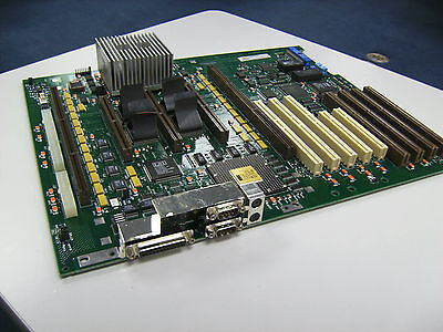
If any of you happen to be trying to get your DEC Alphastation 600 working and are frustrated that there are no LEDs for showing POST codes (power on self test), not my fault.
When I was designing this board I begged our management to ok adding them, but I was not successful because they were in love with this idea of using the LCD to display diagnostic info.
The problem with this is, the LCD is connected to an I2C controller, which is connected to an ISA bus, connected an ISA bridge, connected to our CIA controller chip. All of which need to be configured by the CPU before they can function.
So in other words, pretty much the whole board has to work before we can display any diagnostic about why it is broken. Dumb, the LEDs would not have cost much and not have added much to my already substantial routing headache for this board.
107 notes
·
View notes
Text
For future reference (my own and others), if your TI SilverLink USB cable stops working and starts showing up as "TUSB3410 Boot Device" or similar under device manager (AKA this issue on TI's help page), this is how you can fix it:
Download the TUSB3x10 EEPROM Burner. This is a Windows-only program, but to my knowledge will work on basically any windows machine from XP on -- so long as it's got USB ports. No clue if it'll work in a VM. (You might want to consult this user's manual.)
Download the SilverLink firmware. I got it from here, and compiled it from their de-compilation. It's just a standard 'make' to build. The output file you're looking for is called "ti_graph_link_silver.eep".
Rename "ti_graph_link_silver.eep" to "ti_graph_link_silver.bin".
Open the TUSB3x10 EEPROM Burner, click on the options dropdown and click "Show the 'Program Full Binary Image' button". (page 7 of the manual).
Select the entry under "Computer" labeled "TUSB3410 EEPROM Burner Instance (1.00)".
Set EEPROM size to "64Kb".
Set "File Path" to point to "ti_graph_link_silver.bin". (The renamed .eep, not the original .bin)
I don't know if the VID, PID, Manufacturer string, Product string and Serial # need to be set manually or not with a 'Full Binary Image' burn. Just to be safe, I set VID to 0451, PID to e001, Manufacturer to "Texas Instruments", Product to "TI-GRAPH LINK USB", and checked "Not Serialized"*.
Click the "Program Full Binary Image" button (yellow triangle with the exclamation point), and proceed with the write.
Unplug and re-plug your cable, and it should show up as a SilverLink again!
Additional notes:
The reason that this happens is because the SilverLink cable (revision b, at least) is based on the TUSB3410 microcontroller. That microcontroller's boot process involves checking for an I2C EEPROM containing program code. If it finds that EEPROM and its contents are properly formatted, it'll copy that code into internal RAM and start executing it. If it can't find the EEPROM, or its contents aren't properly formatted, it'll fall back to looking for boot code over USB. Thus: "TUSB3410 Boot Device". Your cable has, in essence, forgotten who it is and and is begging for you to give it a purpose.
The default page-write buffer size (32 bytes) and I2C bus speed (400 KHz) in the burner app are already correct, so no need to change them.
*I don't remember exactly what the Manufacturer string, Product string, or serial number fields were set to pre-corruption. Likewise, no idea about the advanced descriptor options. If someone wants to send the output of lsusb -v -s [whatever their silverlink's bus/id numbers are], I'd really appreciate it!
You might be able to skip the header rigamarole by taking the ti_graph_link_silver.bin file directly ("directly coming from the compiler") -- but I again I don't know exactly what information is in the .eep file and what isn't. Are the PID and VID encoded somewhere in there? I peeked with a hex editor but have no clue. If someone has hardware lying around they're willing to experiment with/potentially brick, I'd love to hear your results!
If you mess up and accidentally forget to do a "Full Binary Image" write, or otherwise brick the firmware, you can force the TUSB3410 to fall back to USB boot mode by opening the plastic shell around the PCB (one Torx screw under the sticker, then just normal plastic tabs) and shorting the right-bottom (Vss) and right-top (SDA), or right-bottom (Vss) and center right-top (SCL) pins of the EEPROM (the chip labeled "24LC64") as you plug it into the USB port. You may need multiple attempts. This works because it temporarily convinces the TUSB3410 that the EEPROM is missing/corrupt, and thus it decides to fall back into USB boot mode -- until you reset it. It might be better to do this with a ~1k resistor instead of a jumper wire, but IDK I'm not an electrical engineer. All I know is that shorting Vss and SDA worked for me. Again, would love feedback.
No clue what causes the corruption in the first place, or how long this fix will last. It might be because the EEPROM's write protect pin is set to "write enable"? It could also just be degrading hardware, for all I know, so no idea how long the fix will last. All I do know is that everything seems nominal right now (immediately after performing this procedure).
10 notes
·
View notes
Text
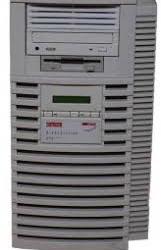
how far is too far
to take this old socket 423 motherboard? it’s really only limited by the boot drive speed and the cpu cooling/fans at this point, it’s nearly maxed out
so socket 423 was the oldest Pentium IV stuff, though it may have supported some celeron chips if i’m not mistaken. The fastest cpu was 2.0GHz with 400MHz RD-RAM bus with 256KB of L2 cache.
What I have was someone’s rejected server board from 1999 that I got used in 2000 or 2001 maybe, and this has been its third refresh 😅 but for the slowest most uncommon p4, it is great, it has ATA100 RAID and that can mean using up to 4 drives as one for more speed or redundancy.
it has irda for some infrared data, several old school serial ports, parallel, AGP 4x, and 5 PCI ports.
I had already given it 2GB of ECC RAM, some multiformat DVD burners (one sports DVD-RAM support), a 3.5” floppy, and even a SATA soft RAID PCI card,
but I am questioning now that SSD’s are cheap, whether 4 SSD’s would be faster over 33MHz PCI soft RAID or ATA100 hardware based RAID at the full 100MHz ? maybe this thing would be seriously fast, for what it is
I also learned that AGP 4x was as much real bandwidth as any GPUs of the era ever could saturate since AGP8x didn’t last long before being replaced by PCI-express 2.0 16x slots for most GPUs… So AGP 8x cards work just fine here.
I found a GeForce 7600 GS 512MB model that needed recapped, amd so I havent tried it; then i found an ATi HD 3650 512MB AGP8x GPU to try in the meantime. Originally in 99 or 2000 this box was rocking an ATi All-In-Wonder Rage 128 card, but I foolishly gave it the ATi All-In-Wonder Radeon 8500dv for the greater 64MB vram and a couple firewire 1394a ports. It was a fine card, but analog TV is gone, rendering the tuner useless, and the A/D/A converter quality was actually pretty bad on this card with a lot of extra noise added on anything you plugged in. Once I got a miniDV camcorder I just used its converters foe everything, as it looked so much better!
I also got it with a Creative Labs SoundBlaster Live! 5.1 card, which was super cool at the time, but until I had any 5.1 speakers to use it with, it was pointless versus the nearly-identical 2-channel onboard AC’97 chip, or the other nearly identical AC’97 chip on the Radeon card! I wasnmt even bright enough to disable the onboard audio in the BIOS, at the time so I was always doing some dumb routing and wasting resources on all 3 sound cards
Then I did something even more dumb later on and got a GeForce MX420 card with the same 64MB vRAM but less rendering capability than the Radeon card at the time. (As I understand it now, these were more of a display adapter than a GPU?)
I’ll try to remember to benchmark these options against one another at some point, bc i have a feeling the GPU and boot drive is going to make all the difference in the gaming performance
Beyond all that, the peripheral cards made a big difference too! I added a VIA 1394 card, an NEC USB2.0 card, and a SiS combo USB2.0 and 1394a card. The NEC seemed much more snappy at USB2.0! I also accidentally disabled the system once by plugging the irDA to the i2c SMbus header below it by mistake. So it has i2c support! I may try to learn how to use it and make a PWM fan controller for it! It would be sick to have something read the core temps and apply the PWM slopes for all the fans accordingly.
IF I can do that, i’ll definitely swap CPU fans! I heard some socket 775 coolers can be adapted to fit! I’d love to know if anyone has experience with adapting the two. If all fails, I have a drill press and a smart g/f…. Maybe I’ll post any updates
should I burden this beast with Vista to run DX10??
#it kinda went from the worst use of said computer to maybe as good as it can be!#technomancy#retro computing#almost
2 notes
·
View notes
Text
ACCESS.bus: The Forgotten USB Competitor
https://tedium.co/2025/02/17/access-bus-i2c-usb-competitor-history/
2 notes
·
View notes
Note
WARNING: LONG ASK INCOMING
For hobby electronics there’s two major kinds of processors: Microcomputers and Microcontrollers. Microcomputers are small full computer systems like the Raspberry Pi, they typically run a general-purpose OS (typically some flavor of Linux) and are useful for the kinds of projects that require basically a full computer to function, but not necessarily individual sensors. They’re a great place to start for people who don’t know a whole ton about programming or working with individual components because they typically can output a true GUI to a screen and have the capabilities of a regular desktop computer. They have a main processor, true RAM, and either large on-board storage space or a way to read a storage device, like an SD card.
Microcontrollers are less complicated (component wise) than microcomputers, but as a result are more difficult for total beginners to begin working with. They’re typically primarily a SoC (System on a Chip) processor without discrete RAM modules and a very small EEPROM (on-ship storage space) and need to have components wired and configured to them to be able to do much more than being a fancy calculator. They’re used for when you need something to carry out electronic functions or get sensor readings, but not necessarily a full operating system, so they’re best suited for small/integrated applications. Your helmet uses a microcontroller to control the LEDs you used in the Cunt Machine post.
I build high-power model rockets as a hobby and with my university team, so I work with both kinds of processor as part of designing payload systems. I typically prefer microcontrollers in these as most of what we do doesn’t need an actual OS to run, and they’re smaller/lighter than microcomputers. One of the advantages of a microcontroller is that it runs a Real-Time OS (RTOS) which forgoes all the user-friendliness of things like windows and linux to instead be the bare minimum backend necessary to run code uploaded into the processor.
The main advantage of using a microcontroller is really that they’re typically a lot cheaper than microcomputers are and are plenty powerful for really embedded applications. They also make other parts of whatever system is being built cheaper/easier to integrate because they require less overhead to function - the raspberry pi needs a minimum of 5 volts of power to work, while a chip like an ESP32-PICO can run at 1.8V.
The main way you make sensors/buttons/peripherals work with a microcontroller is via digital communication busses. There’s a few protocols, the most common being I2C, SPI, and UART. I’ll talk about I2C since that’s generally the most common. With I2C each component is assigned a 2-byte “address” that they’re identified by. When the controller sends a request signal on the I2C data bus, every sensor along the line will return their own signal, marked with their address so that they can be identified. It allows for a large number of devices to be put on the same lines and you can daisy-chain them through each other to the microcontroller.
I’ll be honest I really can’t think of a good way to say much more on the subject as like a starting message because I’ve been working with computers so long all the tech stuff for me is second nature, but if you have any questions ask away I can probably answer them or google them.
.
#AAAAAAAAAAAAAAAAAAAA TY INFORMATION#no yeah this is either really beginner friendly or. friendly to how much i have learned so far#tysm!!!! your insight is consistently so helpful <3#ask#lobsterbitches
27 notes
·
View notes
Text
5 Common Mistakes in Battery Management Systems

There are a few common issues related to the time of adoption and usage of BMS that may affect longevity, safety, and efficiency of a battery pack. Here are five typical errors to avoid:
1. Inadequate Thermal Management
Mistake: Failing to adequately check and regulate the battery cells' temperature.
Consequence: Overheating brought on by poor thermal management might result in thermal runaway, lower battery efficiency, or a noticeably shorter battery life.
Solution: Make sure the Battery Management Systems (BMS) has several sensors for complete temperature monitoring, and when needed, combine it with an active heating or cooling system.
2. Ignoring Cell Balancing
Mistake: Not implementing cell balance in the battery pack or configuring it incorrectly.
Consequence: Ineffective cell balancing can cause individual cells to overcharge or undercharge, which can diminish the battery's total capacity and cause uneven wear and possibly damage to individual cells.
Solution: To ensure consistent charge levels in every cell, use a BMS with either passive or active cell balancing.
3. Overlooking BMS Compatibility
Mistake: Using a BMS that isn't entirely compatible with the battery chemistry or the battery pack's particular setup.
Consequence: Incompatibility can result in improper voltage limits, inappropriate protection, and even unsafe operating conditions.
Solution: Make the BMS specifically designed for the type of battery chemistry used (Lead Acid, Lithium-ion, etc.) and the type of battery pack layout series/parallel arrangement.
4. Inadequate Fault Detection and Diagnostics
Mistake: Not providing enough fault detection and diagnostic tools for the BMS.
Consequence: Faults like short circuits, cell failures, or wiring faults could go unreported without adequate fault detection, resulting in battery damage or dangerous situations.
Solution: Select a BMS (Battery Management Systems) that has advanced diagnostic and fault detection, data logging, real-time warning capability, and communications of problems with other systems or operators
5. Underestimating the Importance of Communication Protocols
Mistake: Integrating a BMS (Battery Management Systems) with other system components without using the proper communication standards.
Consequence: Inaccurate battery status reporting and other inefficiencies can result from poor communication, as might a complete system failure if vital information is not accurately exchanged with controllers or displays.
Solution: The BMS should be able to converse with and connect to the rest of the system: other vehicle control units, chargers, and user interfaces using the necessary protocols: CAN bus, I2C, etc.
Staying away from these common mistakes while selecting and setting a BMS enables you to ensure that your battery pack can serve for as long a time as possible safely and efficiently.
Lithion Power is a manufacturer of high-end Battery Management Systems that can realize maximum performance from any given battery while ensuring safety. BMS developed for electric vehicle applications, energy storage, and portable electronics are highly critical-they offer monitoring and protection with precision to extend the life of the battery and enhance its reliability.
2 notes
·
View notes