#Custom PCB Design
Explore tagged Tumblr posts
Visit Tumblr Blog
Explore Tumblr blogs with no restrictions, modern design and the best experience.
Last Seen Tumblr Blogs


Fun Fact
China blocked Tumblr because of pornography and censorship problems in 2013.
Text
#Mobile App Development#Parts#Supply and Sourcing Strategy#Manufacturing Support#custom PCB design services#end-to-end product development
0 notes
Text
PCB Designing Company in Gujarat
Innovative PCB solutions in Gujarat! Leading design company, expert in precision layouts for optimal performance. Elevate your electronics with us.Get more info and contact details in India.
#PCB Designing Company#Printed Circuit Board Design Services#PCB Layout Experts#Electronic Design and Manufacturing#Custom PCB Design Solutions#High-Quality PCB Prototyping#Gujarat PCB Fabrication
0 notes
Text
“Like a master conductor leading an orchestra, Avalon Technologies harmonizes design, engineering, and production to create the symphony of electronics manufacturing.”
#electronic manufacturing services#EMS#electronic assembly#PCB manufacturing#electronics design services#electronic component manufacturing#OEM services#electronics production#custom electronics#PCB assembly#electronic engineering services#EMS provider#electronic product manufacturing#turnkey manufacturing services#electronics supply chain.
0 notes
Text
Mastering the Art of PCB Design: A Comprehensive Guide

In the rapidly evolving landscape of electronics, achieving optimal performance in high-speed PCB design is paramount. Whether you're a seasoned professional or a novice engineer, this comprehensive guide will explore the key principles and best practices to elevate your high-speed PCB designs. From signal integrity to layout considerations, we'll delve into the critical factors that define the best high-speed PCB designs.
Understanding Signal Integrity
Signal integrity is the backbone of any best high-speed PCB design. To ensure reliable data transmission, it's crucial to comprehend the impact of factors like impedance matching, signal reflections, and crosstalk. Implementing controlled impedance traces and minimizing signal distortions are fundamental aspects of maintaining signal integrity in your design. We'll explore how adhering to these principles can significantly enhance the overall performance of your high-speed PCB.
Strategic Component Placement
Efficient component placement plays a pivotal role in high-speed PCB design. Careful consideration of the location of critical components, such as oscillators and high-speed processors, can minimize signal travel distances and reduce the risk of interference. This guide will provide insights into strategic component placement strategies that optimize signal paths and enhance the overall functionality of your high-speed PCB. Conclusion
In conclusion, best high-speed PCB design requires a holistic approach that encompasses signal integrity, strategic component placement, grounding techniques, and advanced routing practices. By implementing these best practices, you can elevate your designs to new heights of performance and reliability. Stay tuned for more insights into the dynamic world of high-speed PCB design, where innovation and precision intersect for cutting-edge electronic solutions.
0 notes
Note
Cactus fascinates me, does it run on code similar to an existing instruction set or is it completely original on that front?
What can you do with it? What's it's storage?
Both the Cactus (the original wooden prototype from years ago) and the new PCB Cactus(es) are essentially derived from a minimal 6502 computer design by Grant Searle for their core logic. Here's what that would look like on a breadboard:
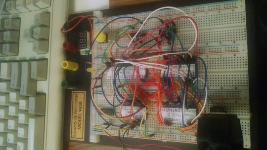
There isn't much to it, it's 32K of RAM, 16K of ROM containing Ohio Scientific's version of Microsoft BASIC, a 6850 ACIA for serial interaction, some logic gates, and of course a 6502 microprocessor (NMOS or CMOS, doesn't matter which). You hook it into a terminal and away you go.
Grant's design in turn can be best described as a distilled, modernized version of the OSI Challenger series of computers. Here's an OSI-400 and a Challenger 4P respectively:

The left one is a replica of the 400 circa 1976, also called the Superboard. It was affordable, endlessly reconfigurable and hackable, but ultimately very limited in capabilities. No BASIC, minimal monitor ROM you talk to over serial, but you could connect it to a bus to augment its features and turn it into a more powerful computer.
Whereas the OSI C4P on the right from about 1979 has more RAM, a video card, keyboard, BASIC built in, serial interface, cassette tape storage, and that's just the standard configuration. There was more room to expand and augment it to your needs inside the chassis (alot changed in 3 years for home computer users).
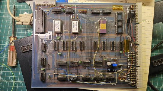
Grant's minimal 6502 design running OSI BASIC is a good starter project for hobbyists. I learned about the 6502's memory map decoding from his design. I modified and implemented his design on a separate cards that could connect to a larger backplane.
Here are the serial, ROM, RAM, and CPU cards respectively:
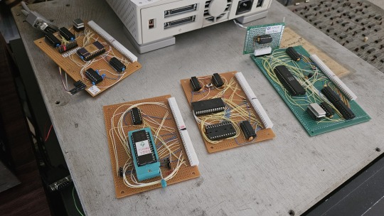
Each one is 100% custom, containing many modifications and fixes as I developed the design. However, that's only half of the computer.
I really wanted a 6502 machine with a front panel. People told me "nobody did that", or couldn't think of examples from the 1970s but that seemed really strange to me. Especially since I had evidence to the contrary in the form of the OSI-300:
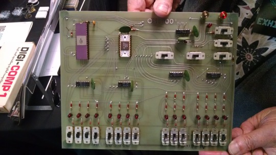
This one I saw at VCF West back in 2018 illustrates just how limited of a design it is. 128 bytes of RAM, no ROM, no serial -- just you, the CPU, and toggle switches and LEDs to learn the CPU. I was inspired the first time I saw one in 2015 at VCF East, which is probably when this whole project got set in motion.
Later that year I bought a kit for a miniature replica OSI-300 made by Christopher Bachman, and learned really quickly how limited the design philosophy for this particular front panel was. It was a major pain in the ass to use (to be clear, that's by OSI's choice, not any fault of Christopher in his implementation)

So... I designed my own. Took awhile, but that's the core of what the Cactus is: my attempt at experiencing the 1970s homebrew scene by building the computer I would have wanted at the time. Over half of the logic in the Cactus is just to run the front panel's state machine, so you can examine and modify the contents of memory without bothering the 6502. I added in all of the things I liked from more advanced front panels I had encountered, and designed it to my liking.
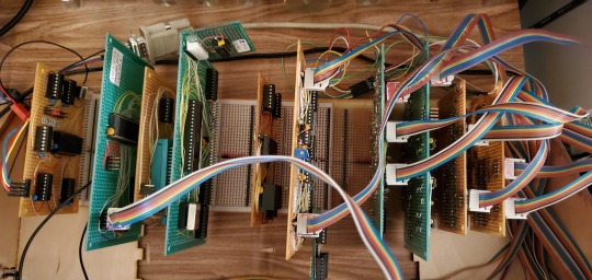
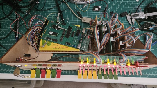
Here's the original front panel, accompanying logic, and backplane connected to the modern single board computer (SBC) version of the machine:
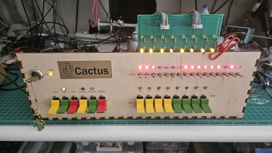
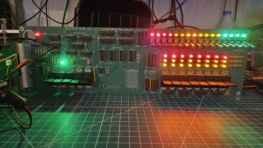
And here's the new Cactus SBC working with the new front panel PCB, which combines the logic, physical switch mountings, and cabling harnesses into a single printed circuit board.
So, what can you do with it? Pretty much the same things I do already with other contemporary 1970s computers: play around in BASIC, fire up the occasional game, and tinker with it.
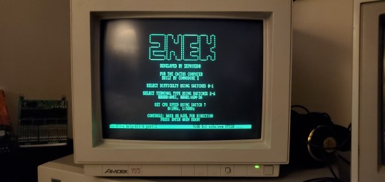
I've got no permanent storage designed for the Cactus as yet, it's been one of those "eventually" things. The good news is that a variety of software can be ported to the hardware without too much trouble for an experienced hobbyist. A friend of mine wrote a game called ZNEK in 6502 assembly which runs from a terminal:
Right now, you have to either toggle in machine programs from the front panel from scratch, burn a custom ROM, or connect it to a serial terminal to gain access to its more advanced features:

Here's it booted into OSI BASIC, but I have also added in a modern descendant of Steve Wozniak's WOZMON software for when I need to do lower level debugging.
I've also got a video card now, based on the OSI-440. I have yet to implement a keyboard, or modify BASIC to use the video board instead of the serial connection. Even if I did, screen resolution is pretty limited at 24x24 characters on screen at once. Still, I'm working on that...


Anyway, I hope that answers your question. Check the tags below to see the whole process stretching back to 2017 if you're curious to learn more of the project's history. I'm also happy to answer any more questions you might have about the project.
267 notes
·
View notes
Text
Mind you, just the CPU. We're not talking about fancy-ass graphics or anything here. Assume something simple like a Z80 or 6501, or a fully custom design that's at most as advanced as either of those. It doesn't even need to have any means of communication beyond some blinkenlights.
14 notes
·
View notes
Text
Does anyone know where I can commission fully custom keyboard? or where to even start? with making one myself Like I don't mean buying a custom keyboard template either. I mean fully custom PCB, shell, everything. I complained on twitter about it, but honestly I've been wondering if it would be worth my time to whip up and learn all of the tools needed to design the keyboard then map it using software like VIA or VIAL. Not sure how expensive it would be to get a printed shell, or even get an aluminum case milled or something. I know that PCB's are kinda cheap.
50 notes
·
View notes
Text
Hell is terms like ASIC, FPGA, and PPU
I haven't been doing any public updates on this for a bit, but I am still working on this bizarre rabbit hole quest of designing my own (probably) 16-bit game console. The controller is maybe done now, on a design level. Like I have parts for everything sourced and a layout for the internal PCB. I don't have a fully tested working prototype yet because I am in the middle of a huge financial crisis and don't have the cash laying around to send out to have boards printed and start rapidly iterating design on the 3D printed bits (housing the scroll wheel is going to be a little tricky). I should really spend my creative energy focusing on software development for a nice little demo ROM (or like, short term projects to earn money I desperately need) but my brain's kinda stuck in circuitry gear so I'm thinking more about what's going into the actual console itself. This may get techie.
So... in the broadest sense, and I think I've mentioned this before, I want to make this a 16-bit system (which is a term with a pretty murky definition), maybe 32-bit? And since I'm going to all this trouble I want to give my project here a little something extra the consoles from that era didn't have. And at the same time, I'd like to be able to act as a bridge for the sort of weirdos who are currently actively making new games for those systems to start working on this, on a level of "if you would do this on this console with this code, here's how you would do it on mine." This makes for a hell of a lot of research on my end, but trust me, it gets worse!
So let's talk about the main strengths of the 2D game consoles everyone knows and loves. Oh and just now while looking for some visual aids maybe I stumbled across this site, which is actually great as a sort of mid-level overview of all this stuff. Short version though-
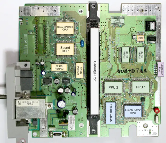
The SNES (or Super Famicom) does what it does by way of a combination of really going all in on direct memory access, and particularly having a dedicated setup for doing so between scanlines, coupled with a bunch of dedicated graphical modes specialized for different use cases, and you know, that you can switch between partway through drawing a screen. And of course the feature everyone knows and loves where you can have one polygon and do all sorts of fun things with it.
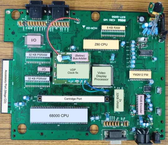
The Genesis (or Megadrive) has an actual proper 16-bit processor instead of this weird upgraded 6502 like the SNES had for a scrapped backwards compatibility plan. It also had this frankly wacky design where they just kinda took the guts out of a Sega Master System and had them off to the side as a segregated system whose only real job is managing the sound chip, one of those good good Yamaha synths with that real distinct sound... oh and they also actually did have a backwards compatibility deal that just kinda used the audio side to emulate an SMS, basically.
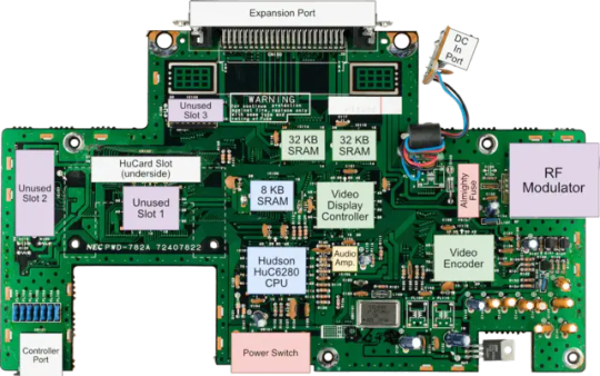
The TurboGrafix-16 (or PC Engine) really just kinda went all-in on making its own custom CPU from scratch which...we'll get to that, and otherwise uh... it had some interesting stuff going on sound wise? I feel like the main thing it had going was getting in on CDs early but I'm not messing with optical drives and they're no longer a really great storage option anyway.
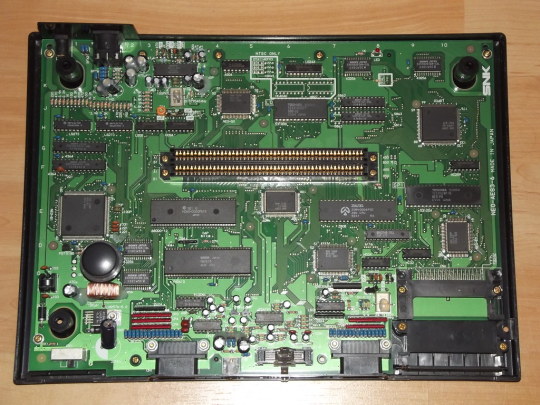
Then there's the Neo Geo... where what's going on under the good is just kind of A LOT. I don't have the same handy analysis ready to go on this one, but my understanding is it didn't really go in for a lot of nice streamlining tricks and just kinda powered through. Like it has no separation of background layers and sprites. It's just all sprites. Shove those raw numbers.
So what's the best of all worlds option here? I'd like to go with one of them nice speedy Motorolla processors. The 68000 the Genesis used is no longer manufactured though. The closest still-in-production equivalent would be the 68SEC000 family. Seems like they go for about $15 a pop, have a full 32-bit bus, low voltage, some support clock speeds like... three times what the Genesis did. It's overkill, but should remove any concerns I have about having a way higher resolution than the systems I'm jumping off from. I can also easily throw in some beefy RAM chips where I need.
I was also planning to just directly replicate the Genesis sound setup, weird as it is, but hit the slight hiccup that the Z80 was JUST discontinued, like a month or two ago. Pretty sure someone already has a clone of it, might use that.
Here's where everything comes to a screeching halt though. While the makers of all these systems were making contracts for custom processors to add a couple extra features in that I should be able to work around by just using newer descendant chips that have that built in, there really just is no off the shelf PPU that I'm aware of. EVERYONE back in the day had some custom ASIC (application-specific integrated circuit) chip made to assemble every frame of video before throwing it at the TV. Especially the SNES, with all its modes changing the logic there and the HDMA getting all up in those mode 7 effects. Which are again, something I definitely want to replicate here.
So one option here is... I design and order my own ASIC chips. I can probably just fit the entire system in one even? This however comes with two big problems. It's pricy. Real pricy. Don't think it's really practical if I'm not ordering in bulk and this is a project I assume has a really niche audience. Also, I mean, if I'm custom ordering a chip, I can't really rationalize having stuff I could cram in there for free sitting outside as separate costly chips, and hell, if it's all gonna be in one package I'm no longer making this an educational electronics kit/console, so I may as well just emulate the whole thing on like a raspberry pi for a tenth of the cost or something.
The other option is... I commit to even more work, and find a way to reverse engineer all the functionality I want out with some big array of custom ROMs and placeholder RAM and just kinda have my own multi-chip homebrew co-processors? Still PROBABLY cheaper than the ASIC solution and I guess not really making more research work for myself. It's just going to make for a bigger/more crowded motherboard or something.
Oh and I'm now looking at a 5V processor and making controllers compatible with a 10V system so I need to double check that all the components in those don't really care that much and maybe adjust things.
And then there's also FPGAs (field programmable gate arrays). Even more expensive than an ASIC, but the advantage is it's sort of a chip emulator and you can reflash it with something else. So if you're specifically in the MiSTer scene, I just host a file somewhere and you make the one you already have pretend to be this system. So... good news for those people but I still need to actually build something here.
So... yeah that's where all this stands right now. I admit I'm in way way over my head, but I should get somewhere eventually?
11 notes
·
View notes
Text
AC PCB Repairing Training Institute
AC PCB Repairing Training Institute: Skill Development
With the increasing demand for ventilation in homes, offices, and workplaces, maintenance planning and maintenance are essential.AC PCB Repairing Training Institute The most important part of an AC system is the circuit board or PCB, which controls the operation of the AC system. Teaching is a great profession where you have to study and get good grades. That’s where the AC PCB Knee Repair Academy comes into play.

Why choose AC PCB Repairing Training Institute?
Enrollment in a professional training school offers the person structured, practical training that cannot be obtained by self-study.AC PCB Repairing Training Institute Professional training teaches students technical skills in AC PCB systems, provides them with practical sessions, and prepares them for actual repair situations. Training schools also give students up-to-date information on the latest trends and tools utilized in the trade.
Major Benefits of Training
An efficiently structured training course covering theoretical and practical topics of PCB repairing.
Practical training in equipment and techniques used in the electronics repairing business
Practice exposure in actual AC PCB faults under the guidance of experienced trainers.
Certification to improve trainees' credibility and marketability.
Training in safety procedures, customer service, and service reporting.
Course Content and Learning Outcomes
A successful AC PCB Repairing Course includes the following:
Introduction to AC components and their uses
PCB design and layout concepts
Understanding the working principle of air conditioners
Decision and diagnosis of common faults in AC PCB
Soldering and desoldering techniques
Use of measurement devices such as multimeters and oscilloscopes
Step by step process of repairing and replacing faulty components
Precautions while repairing
Upon successful completion of this course, students can repair and diagnose various types of AC PCB-related faults independently.
Who should take the course?
This course is suitable for all types of individuals, such as:
School passouts or ITI students interested in technical and job-fit skills
Technicians and electricians who want to offer extension services
Those interested to start small AC or electronics repair shop businesses
Hobbyists interested in repairing circuits and electronics
The course is able to handle fresh entrants with no technical background as well as experienced candidates with experience in electronics.
Choosing the Right Training Institute
While choosing an AC PCB Repairing Training Institute, the following should be kept in mind:
A well-designed syllabus with theory and practical training
Trained faculty with hands-on industry experience
Availability of recent tools and test equipment for training
Good ratings and feedback by students
Employer- and service center-approved certification
Job placement facilities or internship exposure
Choosing a local institute can also provide greater convenience and accessibility.
Career Opportunities After Course Completion
Completing a professional course in AC PCB Repairing makes one conscious of numerous job opportunities, such as:
AC repair specialist with specialized PCB services
Brand service center air conditioner engineer
Independent PCB repair specialist
Home AC repairing and maintaining business owner
Technical support experts in appliance companies
After experience and training, a person can be a good professional in a growing field.
Last Words
Professional training facility AC PCB Repairing Training Institute is a smart investment for any individual who desires to start an electronics repair business. It not only provides real, job-oriented skills but also introduces opportunities for self-employment and professional growth. Choosing an appropriate training facility ensures that you are getting quality training, proper certification, and guidance to be successful in the business.
Begin your career path today by joining a reliable AC PCB Repairing Training Institute and become proficient and confident enough to be a professional electronics repair technician.
2 notes
·
View notes
Text
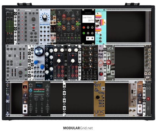
Finally got my Eurorack system updated on ModularGrid — I hadn't gotten around to setting up a few of my custom modules, like the Harald Bluetooth Receiver, the Toy Drum, my true diode Ring Modulator, and my analog logic module "Lola".
Starting with the top left is the Behringer Radar, a contact mic and input amplifier with a gate and a triggered envelope. It's a version of the Mutable Instruments Ears (itself an adaptation of the MTM Mikrophonie); the big change is that all the sensitivity and envelope jumpers are brought out to front panel switches.
Next is one of North Coast Synthesis's "Passive Multiples and Friends", which I built as a mult.
Next is the Behringer Model 182, a clone of the Roland Model 100-series analog sequencer. (A Christmas gift from my wife's parents!)
Next is the MidCentury Modular Dividers, which combines a binary clock divider (simultaneous ÷2 - ÷128) and an adjustable (÷2 - ÷9) divider, both based on CMOS chips. (Built from a PCB/panel set).
Next is my homebrew analog logic module Lola. It has two sections: the unary input which takes one signal and outputs its inverse and its half- and full-wave rectified versions, and the binary input which gives you the OR, AND, and XOR of two signals. (Lola is named that because it's mostly based on the Mutable Instruments module "Kinks". I left off its S&H and added the XOR.)
Next is Chaos, a clone of the MI Marbles random gate and voltage generator.
Next is a set of two low-pass gates, made from vactrols, which I built onto a buggy (malformed) version of my oscilloscope module panel.
Next is my LittleBits Adapter, which lets me plug in the magnet-based circuit building toy modules including those from the Korg collab.
On the second row, we start with the Behringer Model 150, another Roland 100 series clone; this one is noise, a S&H, a ring mod (actually a chip based four quadrant multiplier), and an LFO.
Next looks like another Passive Multiples and Friends, but this one is my Simple Cascading Fixed Amplifier, a set of four fixed amplifiers set up to do x2, x10, or x20 without modifications and up to x400 with self-patching.
The next is a Passive Multiples and Friends, this one an OR Combiner meant to combine multiple gate or trigger signals.
Next is the Kassutronics VCO 3340, an analog VCO I built from the PCB/panel set — basically the CEM3340 chip broken out plus a sine wave output (though the chip is actually the AS3340 clone).
After that is the 3320-VCF by PM Foundations, a low-pass filter with voltage-controlled cutoff and resonance, again built from PCB/panel.
Then it's my first VoxMachina Sigma function/slew generator, followed by a dual attenuverter/mixer, followed by the second Sigma — all together basically a workalike of the Make Noise Maths. The Sigma is very versatile but mostly ends up used for envelopes and LFOs. I had the pcbs and panels fabricated from VoxMachina's uploaded Gerber files.
Next is another Passive Multiple.
The next is a Behringer Four Play, four VCAs that can be used separately or mixed together. It's a functional rip-off of, I believe, Intellijel's quad VCA design.
Next is my homemade ring modulator, a proper two-transformers-and-a-diode-ring unpowered design.
After that, built into another PMaF panel, are two copies of the IamO single-JFET VCA, followed by my version of David Haillant's Simple VCA.
And last in the center row is the Modular in a Week "A Simple Mixer, Right?" (ASMR). A basic five-channel mixer with plain and inverted outputs, I got this as a kit.
In the third row, we start with MiaW's POW, which has LEDs for each power rail, a USB power jack, an external Eurorack power breakout, and a switch that currently doesn't do anything. (I'm still debating whether I should add case lighting.)
Next is a very simple reverse-avalanche oscillator with (not particularly tracking) voltage control, built from LMNC schematics.
Next is the Behringer Brains, their adaptation of the MI Plaits; it's a tremendously versatile voice that's way too tempting to leave on speech synthesis mode.
After that is another Simple Cascading Fixed Amplifier. I think this one uses inverting amplifiers and the other uses non inverting ones?
Next is the Toy Drum — I tore apart one of those electronic drum kits with the roll-up rubber pads and wired up inputs to four of the triggers, giving me a cheap but cheerful kick, snare, hat, and cymbal set.
Next is the Harald Bluetooth Receiver, the module out of a DIY Bluetooth speaker; it'll play stuff off a paired phone, or read files from a microSD card or USB stick.
Next is the DSPFX, a very cheap 100-in-1 audio effects board, which I often use to add end-of-chain reverb/delay and stereo separation. Built from MiaW design, though I had the panel fabricated.
The final PMaF is wired in passive mixer mode; it usually combines the ASMR mixer's output with the stereo output from the DSPFX, the two channels feeding the Phonic, my custom headphones output device (based on the circuit from the Befaco Out).
That's a total of 6 purchased modules, 2 kit builds, 3 PCB/panel builds, 5 PMaF panel builds, 2 fabs from Gerbers, and 13 modules of assorted more custom building, all in a homemade case. Not too shabby, I guess.
2 notes
·
View notes
Text
0 notes
Text
latest Freddie DeBoer seems odd. It's very focused on a sort of consumer-facing understanding of technology for a lot of its runtime. He's not wrong that the changes are smaller than they were in the 1800's but like. That's the low hanging fruit, we all know this, the jump from "not having trains" to "having trains" beats almost any improvement in "trains"
A major change technology has brought to the modern world imo is heavily streamlined manufacturing all across the industrial stack.
If you read like, Bunie Huang's Made in China blog series, in the early 2000's getting a piece of technology made required enormous in-person investment of time and effort working with your manufacturing teams across a pretty broad number of suppliers and industries, you had to get PCB's made, components sourced, moulds designed and set up for injection.
I know people manufacturing small to medium run commercial and industrial electronics, and I did that at my last job. You order machine populated PCB's from your favourite Chinese PCB solutions provider over a web form. If you need ten thousand buttons, you can get that delivered with three emails. Hell, if you want a custom genome to use for some experimental bioreactor, there's multiple competing suppliers who will mail you plasmids that you can customise from online templates and you don't even have to talk to anyone.
And that's just mass manufacturing. If you're making a few thousand of some high end medical equipment, or still in the development phase of design, you can order a titanium laser print to be delivered by the end of the week, or run off a dozen prototypes on your company's fleet of printers using body safe plastics.
Consumer needs don't change much because people are people, we have limited capacity to need things and do things. I've long said that no human can digest more than 50Mbps of media in real time, really. One home cook can only economise their movements so much. A food processor and a pressure cooker can save you some time but the solution to"I want to spend less time cooking at home" will eventually become "don't cook at home, lean on industrial manufacturing of food" and that's fine. There's only so much tech can improve your individual experience before you become the bottleneck.
Faster computers sure, means you can edit video on your phone a little quicker (also hey people ARE editing video on their phone, despite what this blog post says) but it also means Netflix can serve their 4 Petabytes of video library at 400+Gbps from a single server occupying less than 50 liters of space.
It seems disingenuous to act like consumer products feeling stagnant means technology is stagnant.
21 notes
·
View notes
Text
“Riding the wave of innovation, Avalon Technologies is not just keeping pace with the electronics manufacturing industry, but setting the rhythm.”
#electronic manufacturing services#EMS#electronic assembly#PCB manufacturing#electronics design services#electronic component manufacturing#OEM services#electronics production#custom electronics#PCB assembly#electronic engineering services#EMS provider#electronic product manufacturing#turnkey manufacturing services#electronics supply chain.
0 notes
Text


my collection of pedals with acid-etched artwork done by my friend Russell (ig: @ acidrainpedalworks)
top: Digital Scream & ASD, my original designs
mid: Judas & Super Soda Jerk, an original circuit and Devi Ever clone/tribute by acidrainpedalworks
bottom: Noise Swash, clone of the 4ms pedal using a custom-etched PCB also by acidrainpedalworks
9 notes
·
View notes
Text
in 2022 i put an arduino in an altoids tin with a gas station usb power bank and had it run bitlash on an oled. i used the space really inefficiently by breaking out the pins in the weirdest way possible, there was interference on the connection to the oled module that made it fail to initialize half the time, and the battery would automatically shut off after like 60 seconds if there wasn't a phone plugged in. i added a little usb keyboard emulation cause it was an atmega32u4 but it kept crashing or something. also i designed and ordered a custom pcb for the keyboard but then i went and bought an m5stack one cause once i saw the bag of all the tactile switches and put a few of them on, i realized i didnt wanna do all that surface mount soldering myself lmao this was what i had before i knew what a flipper zero was i wanna do a version 2 of this though cause like its so cute its just a little guy. i love altoids tin computers theyre literally snack sized

4 notes
·
View notes