#DC Voltage Symbol
Explore tagged Tumblr posts
Visit Tumblr Blog
Explore Tumblr blogs with no restrictions, modern design and the best experience.
Last Seen Tumblr Blogs


Fun Fact
130K people were victims of a chain letter scam that affected Tumblr in May 2011.
Text

Angus Young, the co-founder and lead guitarist of AC/DC, is a towering figure in rock history despite his modest stature. Known for his frenetic energy, iconic schoolboy outfit, and electrifying guitar riffs, Young has been the driving force behind AC/DC since their formation in 1973. Born on March 31, 1955, in Glasgow, Scotland, he emigrated to Australia with his family in the early 1960s. Angus and his brother Malcolm Young started AC/DC, blending raw rock and blues influences to create their signature hard rock sound.
Young's guitar work, especially on tracks like “Highway to Hell,” “Back in Black,” and “Thunderstruck,” is celebrated for its power, precision, and unforgettable hooks. His dynamic stage presence, including his duckwalk and spinning guitar solos, has made him one of rock’s most compelling performers. Throughout AC/DC’s storied career, Young has remained committed to the band’s no-frills, high-voltage approach to rock, even after significant lineup changes and personal challenges.
Angus’s influence extends beyond his playing; his passion and work ethic have made him a symbol of resilience in rock. AC/DC's induction into the Rock and Roll Hall of Fame in 2003 solidified their status as legends, with Young standing as a cornerstone of their legacy. He continues to inspire generations of guitarists and fans worldwide.
58 notes
·
View notes
Text

Compass Alliance Unlimited - and now in COLORED version
inspired by the recent dc comic series: Justice League Unlimited by mark waid and dan mora, i initially started all that as a sketch on a little sketchbook, and suddenly i decided to inked that in photoshop,
the entire cast of the compass alliance:
upper panel: Paladin, Voltage, Lady Astral, Captain Space, Hydro-Zen, Mark Venture, and Guardian Angel.
lower panel: Metalclad, Sand Nomad, Red Mole, Northlight, Dragon Fighter, Size, Gigantic, King Sodalite, Mariposa, Optimus Quantum, Rubberman, Timer, Symbol, Eastwind & Sunshine, Wetlander, Rocket Prime, Guardsman, Comrade, Jupiterian, Captain Phoenix, Equinox, Archer, Luna, Snowie, Unicorn, The First Maccabi, Wonderbeast, Johnny b. Goode and his butler Zap, Bulldog, Dynamite, Speedmax, Nighthunter, Tsunami, Doctor Palladium, The Historian, Enforcer, Melody, Lion-Man, Kid Dimension, Princess Dream, Doctor Physics, Bloom, Honeybee, Third-eye, Spectrum Man, The Scarab, Captain Space II, Techno, Western, Frankoman, Ivory, Cheerstar, Rags the mummy, and Squire.
This is my most epic and massive sketch ever...
#comics#art#cartoon#fantasy#action#artists on tumblr#drawing#superheroes#colors#compass alliance#ocs#my ocs#sketch#creative arts#illustration#digital art#digital illustration#ocs superhero#jlu#justice league unlimited#epic#dynamic#ambition#massive cast#large cast#superhero team#oc team#digital comics#webcomic#indie comics
6 notes
·
View notes
Text
[ID: Screenshot of a twitter post by “OCCULT GANGSTER MO…” @DUDEDOTWEB. Attached image to the tweet by braincoreconnection (hi-tek) @COREC… shows a photo of a label from an ISG 12 Volt AC Adaptor. From top to bottom left to right: A box that reads: “Input: 100V-240V— 0.75A-0.4A, 50-60Hz / Output: 12V — 3A.” A box that contains a diamond icon containing the letters PS. The word “JET.” A box within the box that contains the letters “JRC.” / AC 100V 70VA 50-60Hz DC / 12V3A. A box that reads: “MPA-AC1 / 100-V 0.75A-0.4A 50-60Hz and a circular logo containing 3 letter-C’s and a “TM” symbol, labelled “AD004332” / 12C — 3 A” A box that contains a triangle hazard symbol for “high voltage” and a triangle hazard symbol for “caution” flanking a smaller box with: “CAUTION / risk of electric shock do not open.” A box containing the text: “-For customers in Korea- / Manufactured by GUANLAN NNJRC ELECTRONICS / A/S: 02-782-3313 (Korea) with a logo of a stylized “K” inside an oval, labelled “KTL SU10021-3001.” Below that box, text reads: Complies Canada ICES-003/NMB-003 / Identification Systems Group. A logo that is the letter “C” followed by a large circle enclosing the letters “U-L” followed by the letters “U-S,” below this logo reads: “Listed / I.T.E. / Power Supply / E133304. Beneath that is text: “NSW18373” and a checkmark inside a circle. A Box containing a logo that shows indistinct small text arranged in a circle that encloses a triangular symbol and the letters “TUV” and more indistinct text. Another logo that is a big blocky letters “G-S” and indistinct text. Below is the marking, large, of curved and stylized letters “C-E.” In the upper right corner, text reads: “Also listed / as a / audio/video / apparatus.” Below is an ovular logo shaped like a stylized curving “C” containing a letter “P” inside the thick body of the C and a tiny capital “T” pinched between the prongs of the “C”. Below is an icon depicting a house with an arrow going inside. Below is a square containing a square, labelled “double insulated.” Below is an icon depicting a garbage can with an “X” over it. /end ID]

24K notes
·
View notes
Photo

https://pcport.co.uk/what-is-a-dc-port-on-a-computer-monitor-mean-explained/ The DC port is a crucial component on most monitors, serving as the primary power inlet. Unlike other ports that transmit data, such as HDMI or DisplayPort, the DC port supplies power to the device.A power adapter is used to convert AC power from a wall outlet into DC power that the monitor can use. The DC port is typically marked with a specific symbol or label, making it easily identifiable.In this comprehensive guide, we'll explore the technical aspects of DC power delivery, including voltage
0 notes
Text
How to Use a Digital Multimeter: A Step-by-Step Guide
If you’re new to using a multimeter or want to make sure you’re using your Ultrics Multimeter effectively, you’re in the right place! This simple yet powerful tool is essential for measuring electrical values like voltage, current, and resistance. Here’s how to get started:
1. Set Up Your Multimeter
Before using the Ultrics Multimeter, ensure it’s properly set up for the task at hand.
Turn On: Press the power button to turn it on.
Select Function: Use the dial to select the measurement type you need — DC Voltage (V with a straight line), AC Voltage (V with a wave symbol), Current (A), or Resistance (Ω).
2. Testing Voltage
To measure the voltage in a circuit:
Set the Multimeter to Voltage (V): Choose DC for batteries or AC for household outlets.
Insert Probes: Connect the red probe to the “V” terminal and the black probe to the “COM” terminal.
Touch the Probes to the Circuit: Place the red probe on the positive end and the black probe on the negative end of the component you’re testing.
Read the Display: The voltage reading will appear on the screen. If it’s too high, switch to a higher voltage range.
3. Testing Current
To measure the current flowing through a circuit:
Set the Multimeter to Current (A): Ensure the dial is set to either AC or DC current.
Swap Probe Connections: Move the red probe to the “A” terminal (sometimes labeled with an arrow).
Break the Circuit: To measure current, you’ll need to place the multimeter in series with the circuit — meaning the current must flow through the multimeter.
Read the Display: The current value will appear on the screen. Always start with the highest range to prevent overloading.
4. Testing Resistance
To check the resistance of a component:
Set the Multimeter to Resistance (Ω): Use the dial to select the resistance setting.
Insert Probes: Place the black probe in the “COM” terminal and the red probe in the “Ω” terminal.
Test the Component: Touch both probes to the leads of the component you’re testing.
Read the Resistance: The value will be displayed on the screen. If you get a reading of “OL” (Over Limit), it means the resistance is too high to measure on the selected range.
5. Safety Tips
Always start with the highest range to avoid damaging your multimeter.
Check the battery in your multimeter before use — low power can affect readings.
Disconnect the power when measuring current, and always ensure you’re measuring current in series.
Wear safety gloves when testing high-voltage circuits.
Conclusion:
The Ultrics Multimeter is a versatile tool that can help you diagnose electrical issues quickly and accurately. Whether you’re testing the voltage in a car battery or checking the resistance of a resistor, following these steps will ensure you get the right readings. Happy measuring! 🔧💡
1 note
·
View note
Text
AC/DC Power Up Tour 2025 Limited Edition Nike Air Force 1

Product link:https://flavorhauted.com/product/ac-dc-power-up-tour-2025-limited-edition-nike-air-force-1/
Store link:https://flavorhauted.com/
High Voltage on Your Feet: The AC/DC Power Up Tour 2025 Limited Edition Nike Air Force 1 Is Rock ‘n’ Roll Royalty in Sneaker Form
In the pantheon of legendary music-meets-fashion collaborations, few rival the sheer shockwave of the AC/DC Power Up Tour 2025 Limited Edition Nike Air Force 1. This isn’t just a sneaker — it’s a lightning strike of attitude, nostalgia, rebellion, and sonic energy. It’s an anthem for the feet. Born from the timeless electricity of AC/DC and the iconic silhouette of the Nike Air Force 1, this sneaker is the ultimate tribute to fans who believe in one thing: Rock or bust.

Electrifying Design That Screams Stadium Rock
From the moment you lay eyes on these kicks, they radiate a pulse of pure power. The classic Air Force 1 low-top frame has been recharged with a visual jolt — a palette of electrifying blues, jet black, and storm-white that channels the raw thunder of AC/DC’s sound. The entire sneaker is a visual concert, exploding with high-voltage aesthetics and relentless edge.
Wrapped across the mid-panels and heel is a dynamic lightning bolt graphic, flashing through a cosmic blue haze that feels straight off the stage lights of an arena tour. The background imagery hints at guitar strings, amplifier coils, and shockwave patterns — almost as if Angus Young’s Gibson SG just sent a tremor through the fabric.
Boldly placed across the side is the unmistakable AC/DC logo, forged in steel-gray gothic font, shining like a guitar pick tossed into the crowd. Above it, in clean capital text: "PWR/UP" — the name of their triumphant 2020 album and the spirit of the 2025 tour. This isn't just branding — it’s an invocation. A call to rise, to roar, to never dial it down.

The Details Are in the Decibels
What separates these sneakers from typical band merch is the meticulous attention to craftsmanship and symbolism. The signature Nike Swoosh is outlined in crisp white — a visual bolt cutting across the stormy upper. It adds contrast and clarity to the chaos, like a perfect solo slicing through a wall of sound.
The tongue and heel tab feature classic Nike branding, but with custom fonts and color treatments that echo the rebellious spirit of rock. The inner lining is cushioned for comfort, yet it carries subtle design nods — thunderbolt stitching, tour date references, and possibly (if you look closely) a silhouette of the band mid-performance.
These shoes are louder than leather. Built with premium materials that blend durability and flex, they’re meant to hit pavement like a bass drum hits the floor — hard, rhythmic, unforgettable.
More Than Merch: This Is A Movement
For fans of AC/DC, these shoes are not just a style choice. They’re a statement of identity. They say you’ve felt the fire of “Back in Black,” you’ve headbanged to “Thunderstruck,” and you understand the sacred sound of a power chord at full blast. Owning these kicks is like wearing a piece of history, with every step echoing the stomp of a drumbeat and every scuff mark telling a tour story.
And for sneakerheads, this drop is a grail-tier flex. Nike Air Force 1s are no stranger to reinvention, but this edition hits a cultural note that’s truly rare. It blends the aesthetic of high fashion with the rawness of rock, making them wearable whether you're moshing at a festival or walking city streets with headphones blaring.
PWR/UP in Every Step
One of the most powerful messages this sneaker delivers is right there in its name: PWR/UP. It’s a lifestyle. It’s about unleashing energy, refusing to dim your fire, and stepping into each day with a stage-ready strut. This shoe isn’t just for concert nights — it’s for those who walk with purpose and passion. Who don’t just play music, but live it.
Even the sole has that signature Air Force 1 energy return — bounce, comfort, and classic court style. But here, it’s charged with something more: attitude. Like the opening riff of “Hells Bells,” it hits you in the chest and dares you to keep up.
A Collector’s Crown Jewel
Let’s be real — this sneaker won’t stay on shelves long. As a limited edition drop tied to AC/DC’s 2025 Power Up Tour, it's destined for resale markets, collector showcases, and grail walls. But if you’re lucky enough to score a pair, know this:
You’re holding more than a sneaker. You’re holding an artifact of modern rock history. A bridge between music and streetwear. A time capsule of sound and style.
Frame it, wear it, worship it — just don’t ignore it.
Final Verdict: A Rock God in Sneaker Form
The AC/DC Power Up Tour 2025 Nike Air Force 1 is a triumph of design and devotion. It crackles with charisma, walks with swagger, and honors two legacies that have always gone their own way. For the fans, the faithful, and the fearless, this is your anthem in lace-up form.
So turn up the volume. Lace up the storm. Step into the arena of life like you own the stage.
0 notes
Text

Component description of PCBA patch processing
PCBA patch processing mainly includes two major processes: PCB circuit board production and SMT patch processing. Electronic components are indispensable in the process. Electronic components are the basic part of PCBA patch processing and an important factor affecting the performance and quality of PCBA finished products. So what are the commonly used electronic components for PCBA patch processing?
1. Resistor
Resistors are electronic components with resistance characteristics and are one of the most widely used components in PCBA processing. Resistors are divided into fixed resistors and variable resistors (potentiometers), which play the role of voltage division, current division and current limiting in the circuit.
2. Capacitors
Capacitors are also one of the basic components in PCBA processing. They are components that store electrical energy and play the role of coupling, filtering, DC isolation and tuning in electronic circuits.
3. Inductor coils
Inductor coils are referred to as inductors and have the function of storing magnetic energy. Inductor coils are usually composed of skeletons, windings, shielding covers, magnetic cores, etc.
4. Potentiometers
Resistors with variable resistance values, that is, resistors that can be continuously adjusted within a specified range, are called potentiometers. The potentiometer consists of a housing, a sliding end, a rotating shaft, a ring resistor and three lead-out terminals.
5. Transformer
The transformer consists of an iron core (or magnetic core) and a coil. The coil has two or more windings, of which the winding connected to the power supply is called the primary coil, and the remaining windings are called the secondary coil.
The transformer is a device that converts voltage, current and impedance. When an AC current flows through the primary coil, an AC magnetic flux is generated in the iron core (or magnetic core), causing a voltage (or current) to be induced in the secondary coil. The transformer is mainly used for AC voltage conversion, current conversion, power transmission, impedance conversion and buffer isolation, etc. It is one of the indispensable important components in the PCBA machine.
6. Crystal diode
The crystal diode (i.e. semiconductor diode, hereinafter referred to as diode) is made of a PN junction, electrode leads and an external sealed tube shell, and it has a unidirectional conductive characteristic.
7. Crystal triode
The crystal triode (hereinafter referred to as triode) is the core device for signal amplification and processing, and is widely used in PCBA machines.
8. Field Effect Transistor
Field effect transistor (FET for short) is also a semiconductor device with PN junction. Unlike triode, it does not use the conductive property of PN junction, but its insulating property.
9. Electroacoustic Device
The device used to complete the conversion between electrical signal and sound signal in the circuit is called electroacoustic device. There are many types of it, including speakers, microphones, headphones (or earplugs), transmitters, receivers, etc.
10. Photoelectric Device
Photoconductive devices that work with the photosensitive properties of semiconductors, photovoltaic cells and semiconductor light-emitting devices that work with semiconductor photovoltaics are collectively referred to as photoelectric devices.
11. Display Device
Electronic display device refers to a photoelectric conversion device that converts electrical signals into optical signals, that is, a device used to display numbers, symbols, text or images. It is a key component of electronic display devices and has a great impact on the performance of display devices.
12. Sensor
The sensor can sense the specified measured value and convert it into a usable signal according to a certain rule. It is usually composed of a sensitive element and a conversion element.
13. Surface Mount Components
Surface mount components (SMC and SMD) are also called patch components or chip components. They include resistors, capacitors, inductors and semiconductor devices, etc. They have the characteristics of small size, light weight, no leads or very short leads, high installation density, high reliability, good vibration resistance, and easy automation.
14. Thyristor
SCR, short for silicon-controlled rectifier, is a high-power semiconductor device with a four-layer structure of three PN junctions, also known as thyristor. It has the characteristics of small size, relatively simple structure and strong functions, and is one of the more commonly used semiconductor devices.
15. Switches, relays, and various connectors
Switches are used to cut off, connect or convert circuits in electronic equipment. Relays are automatic control devices that will change the output in a jumpy manner when the input quantity (electricity, magnetism, sound, light, heat) reaches a certain value.
If you have interest in our service, please feel freely contact Cynthia at [email protected] & 86 18126197150.
0 notes
Text
Harnessing the Deep: The Magic of Marine Electrical System.

Introduction.
Marine electrical system play a vital role in the world of maritime. Providing the lifeblood of power and functionality to boats and ships of all sizes. These intricate networks of wires, circuits and components enable vessels to navigate treacherous waters, access resources and maintain safety at sea. In this exploration, we delve into the fascinating realm beneath the ocean's surface where the principles of electricity converge with maritime technology. From the fundamentals of electrical circuits to the latest advancements in sustainable energy solutions and smart monitoring systems. Marine electrical system are at the forefront of maritime innovation shaping a cleaner more efficient and safer future for seafarers worldwide. The Vital Role of Marine Electrical System. Imagine this: the glowing lights on a ship cutting through the dark night, the soothing sound of the engines moving the ship forward and the complex network of wires and circuits making it all work perfectly. Let’s explore the important parts of this system and how they make everything run smoothly. Why We're Exploring Marine Electrical System? What makes us want to explore the thrilling world under the ocean? Marine electrical system have more to offer than just convenience. They help us in many ways, such as allowing us to discover amazing underwater environments, find resources and stay safe at sea. Here we'll learn about the benefits and the incredible things marine electrical systems can do as we endeavor into the deep sea.
The Basics of Marine Electrical System.
There's a complicated network of wires and electrical stuff that makes the whole boat work that hidden below the decks and walls of every boat. This electricity does things like lighting up the boat and making it move through the water. Let's see about the basics of these electrical systems that power boats and ships. The Building Blocks: Understanding Electrical Circuits. Think of marine electrical systems like a big city with lots of roads where electrical circuits are like the roads that let electricity flow smoothly. They are like a loop where tiny particles called electrons travel from a power source to different parts of a boat and then come back. So, electrical circuits make sure that power goes everywhere on the boat, just like roads in a city help people get to different places. The Fundamentals of Marine Electrical System. To understand marine electrical system, we need to know about three key things; voltage, current, and resistance. Voltage: In electricity, it's the force that pushes electrons to move. Current: Current measures how many electrons are actually flowing through a wire. Current measure it in units called amperes. Resistance: Resistance is like an obstacle in the path of flowing electrons. The symbol Ω to represent resistance. So, voltage pushes electrons, current shows how many are moving and resistance resists their flow. These concepts are important in marine electrical systems. AC vs. DC: What Sets Marine Systems Apart? There are two main types of electricity: AC and DC. AC goes back and forth in a regular pattern and is good for sending power over long distances. DC keeps a steady flow of electricity and is good for things that need a stable power source. Marine electrical systems often use both AC and DC to handle different tasks because they have to deal with changing conditions at sea. From Generator to Outlet: Power Generation and Distribution. On ships, electrical generators take different energy sources like diesel, natural gas or even new ones like LNG and turn them into electrical power. This power then goes through the ship's electrical system to provide electricity for various purposes. Types of Generators Used in Marine Applications. Generators used on boats come in different sizes and types depending on the boat's needs. Big ships use large, powerful generators for things like moving the ship, lighting and running equipment. Smaller boats like yachts and fishing boats use smaller, efficient generators. These generators can run on diesel fuel or use eco-friendly technology like hybrid systems as the marine industry moves towards using cleaner energy. Power Distribution Networks on Vessels. Electrical systems on ships work like a network of power that spreads everywhere on the vessel. They use control panels, circuit breakers and switchboards to control and protect the flow of electricity. These systems provide power for lights and other important functions. Making it possible for ships to travel all over the world. They use things like generators to create electricity and then distribute it to different parts of the ship so that everything works well on the open sea.
Navigating the Complexity: Components of Marine Electrical System.
Marine vessels have lots of complicated technology on board but two really important things are marine batteries and control panels. These things help the boat run smoothly and stay safe. Let's see what they do, the different kinds, how to take care of them and why they matter for boats. Marine Batteries: The Lifeblood of Onboard Power. Marine batteries store and provide electricity for important things like starting engines, lights and electronic devices. Types of Marine Batteries and Their Applications. There are different kinds of marine batteries, each designed for a specific job. Starting batteries give a quick burst of power to start the boat's engine. Deep-cycle batteries provide steady energy for a long time like when running onboard equipment. Dual-purpose batteries are a mix of both so they give you a balance between quick power and long-lasting energy. Choosing the right type of battery makes sure everything on boat works smoothly from the engine to the navigation system. Battery Maintenance. Taking care of marine batteries is really important to make sure they work well. It means regularly checking the liquid inside them and making sure the metal parts stay clean. Switchboards and Control Panels: The Captain's Command Center. In a ship's electrical system there are control centers that help electricity move around, keep things safe and let the captain and crew control everything on the ship such as lights and navigation. Functions and Features of Marine Control Panels. Marine control panels are like the brains of a ship's electrical system. They have buttons and switches that help sailors control important things on the ship. Such as the engines and electricity. These control panels are very accurate and reliable. So, the sailors can make sure everything is working well. They also have fancy features that make the ship safer and more efficient when it's out at sea. Ensuring Safety and Reliability in Control Systems. In the unpredictable ocean environment, it's really important for boats to be safe and reliable. Control systems have special features to protect against problems like shutting off power if something goes wrong and they can also keep an eye on things to make sure everything stays working well even when the sea is rough. Lighting the Way: Marine Lighting Systems. When the sun goes down and it gets dark on the water, special lights on boats come on to help them navigate safely. These lights include navigation lights and newer LED lights which are very energy-efficient and bright. Navigation Lights: A Crucial Aspect of Safety. Navigation lights on boats are like a secret code that ships use to communicate with each other at sea. These lights tell other ships important information like where they're going, how big they are and whether they're moving or stopped. It's really important for everyone who works on the water to understand these lights to stay safe and avoid accidents. LED Technology: The Energy-Efficient Revolution. LED lights are making a big change in boat lighting. They use less energy that lasts a long time and work well in tough conditions. This is good for the environment and also helps boats save money on energy and be kinder to nature.

Powering Ahead: Advancements in Marine Electrical Systems.
The constant progress in marine electrical systems is moving ships toward a cleaner and more efficient future. Let’s look at the newest developments that are taking boats into the next stage of maritime technology. The Green Wave: Sustainable Energy Solutions. The shipping industry is focusing on being more environmentally friendly. One important way they're doing this is by using cleaner energy sources to power ships instead of relying on polluting fossil fuels. Embracing Renewable Energy Sources. Ships are using solar panels and wind turbines to get energy from the sun and wind. This clean energy is changing how ships power their systems. Hybrid and Electric Propulsion Systems: A Cleaner Future. Ships are using new technology to move forward with less pollution. They're using a mix of regular engines and electric motors. So, they can switch between them when needed. This is good for the environment and helps save fuel and reduce pollution. Digitalization Takes the Helm: IoT and Marine Electrics. The internet and technology are becoming important on ships like sensors and machines on boats are getting smarter and connected to the internet. This helps ships work better and be safer. Smart Monitoring Systems for Efficient Operations. Sensors on boats gather information about different things like how the engine is working, how much fuel is being used and what the weather is like. This information is sent to a control center on the boat. So, the crew can make smart choices, improve how the boat works and find upcoming problems early. Predictive Maintenance: Avoiding Breakdowns at Sea. One important use of IoT in marine electrical systems is predicting when the equipment might have problems. Smart computer programs look at data and figure out when things might break or need fixing. This helps avoid expensive breakdowns while ships are out at sea, keeping them running smoothly and safe.
Conclusion.
To sum it up, marine electrical systems are really important for boats and ships. They help power these vessels and keep them safe. It's important to understand basic stuff like voltage, current, and resistance as well as the use of different types of electricity (AC and DC) in this context. There are some cool things happening in this field. People are working on using cleaner sources of energy like solar panels and wind turbines to make ships more efficient and eco-friendlier. They're also using smart technology (IoT) to make ships safer for the crew and better for the environment. Read the full article
0 notes
Text

Most Popular Band Merchandise of All Time
Some bands don't just create music; they create movements. Their merchandise becomes more than just clothing and accessories; it's a symbol of belonging to a tribe, a testament to their enduring legacy. 🎵👕 Here are some of the most popular bands whose merchandise has sold the most and the iconic items that made fans go wild. ⭐️
1. The Beatles 🇬🇧🎶
The Classic Tee: The famous Fab Four pose.
Yellow Submarine Everything: From tees to lunchboxes.
Album Art Prints: Iconic cover art on display.
2. Pink Floyd 🌈🔍
The Dark Side of the Moon Prism Tee: Instantly recognizable.
Wish You Were Here Vinyl: A collector's dream.
The Wall Hammers: Wearable art.
3. Led Zeppelin 🌄✈️
Stairway to Heaven Tee: A stairway to style.
Zoso Symbols Jewelry: Mystical and mesmerizing.
IV Vinyl: The soundtrack of a generation.
4. AC/DC ⚡🤘
High Voltage Logo Tee: Electrifying fashion.
Angus Young's Schoolboy Outfit: Halloween favorite.
Back in Black Vinyl: An album for the ages.
5. Metallica 🤟🔥
Metallica Ninja Star Tee: Bold and fearless.
Master of Puppets Vinyl: Thrash metal perfection.
Ride the Lightning Guitar Pick: Play like a rock god.
6. Nirvana 🤘🎸
Smiley Face Tee: A symbol of grunge.
In Utero Vinyl: The sound of the '90s.
Kurt Cobain's Iconic Sunglasses: A piece of rock history.
7. Grateful Dead 🌹🐻
Dancing Bears Tee: Colorful and iconic.
Live/Dead Vinyl: A journey through psychedelia.
Tie-Dye Everything: The essence of the Dead.
8. Queen 👑🎤
Freddie Mercury's Crown Tee: Fit for a legend.
A Night at the Opera Vinyl: Operatic rock brilliance.
Bohemian Rhapsody Scarf: Wrapped in rock history.
9. Rolling Stones 🎸👅
Tongue and Lips Tee: The most famous logo in rock.
Exile on Main St. Vinyl: Rock 'n' roll in a groove.
Keith Richards' Skull Ring: Legendary style.
10. U2 🌍🎶 - The Joshua Tree Tee: A desert dream. - War Vinyl: War-era anthems. - Bono's Iconic Sunglasses: For the ultimate cool factor.
A World of Rock and Roll Fashion 🌟🎵 These bands didn't just sell music; they sold a lifestyle, an attitude, and a piece of history. Their merchandise continues to be treasured by fans worldwide, a way to keep the spirit of rock and roll alive. From classic tees to vinyl records, these iconic items are more than just merchandise; they're symbols of the enduring power of music and the timeless appeal of rock legends. Rock on! 🤘🎸👕 Explore uber-cool merch from these legendary Bands ➡️ Band Merch
#the beatles#pink floyd#queen band#freddie mercury#john lennon#ringo starr#paul mccartney#george harrison#david gilmour#acdc#angus young#metallica#james hetfield#nirvana#kurt cobain#band merch#rock music#band tshirt#grateful dead#rolling stones#the rolling stones#u2
0 notes
Text

I'm trying to get the right Lift Chair replacement class to power Supply AC/DC Transformer 100-240V 50-60 HZ 4A
Then on the DC side 13.8V 5000mA
And apparently 13.8 volt is a maximum potential capacity it's not necessarily what's flowing through but if I try to find something exactly with 13.8 volts which is a very odd voltage I am getting all kinds of weird stuff and when I try to find something that's 4 amps as maximum capacity potential on the AC side I'm getting all kinds of weird stuff so I'm doing a step up to 15 volts and 5 amps on the DC side and that should cover it because that is power and Flow rate. That will cover the previous power and flow rate I don't need any more than that I don't need any less I'm tired of trying to figure this out I have been reading formulas and information the problem is class 2 power supply is mostly an artificial designation and today the safety and the rating of a power supply is apparently shown by symbols and I probably should have bought the one that had like about the cajillion symbols on it because it probably covered everything but it might have been saying you can't use it for this but you can use it for that and I don't have any idea what it means and I have to study electronic symbols on Transformers power supplies for AC/DC. I have already had to replace some fixtures that were put in this house because they were sparking and catching on fire because somebody put in probably some sale or incorrect or bad quality or damaged fixtures one light fixture and one electrical outlet. After one started sparking and shootings Sparks out and smoking and start the catch on fire such as I flipped the fuse box and when the electricity and everything stopped I pulled it I kept the wires I went out and bought the best electrical outlet I could buy at the time for that with a power surge button on it. My friend at the time who did electronic systems and security systems yes this will work but you didn't have to buy anything that's good I said I don't care after what I saw I was getting something I knew that would pop before it started sparking The Surge protect button because I'm not sure if it has anything to do with the wiring back there and I've not had any problems since. Since two fixtures did the exact same thing I think that guy went to a discount place or use some used ones and that's not a good idea with electronics you want the best that is necessary because less can be dangerous in electronics because overheating can cause fires cheap can be dangerous in electronics
0 notes
Text
Stompbox Studies - Class 1
Want to build your own effects pedals? A good place to start is understanding how transistors work. Transistors are those three legged devices seen populating many stompbox circuits.
Transistors are are a core building block in electronics. Integrated circuits, like op-amps, are made up of many transistors! Transistors are used in all of the circuits you’ve probably played or heard on recordings: Rangemaster, Fuzz Face, Tonebender, Big Muff, Tube Screamer, and too many more to list here.
The goal of this series of blog posts will be to present concepts you can use to understand how guitar effects pedals work, apply these ideas to debug, and make your own pedals.
Why I am I doing this? I have been building Stompboxes as a hobby for years now and want to build a deeper understanding of the electronic concepts underneath it all. I have been building pedals for years but it has always been sort of paint by numbers. I had some friends get into the hobby recently and they had lots of questions. Here are the answers I could come up with.
This class will be broken into three parts: a discussion in this blog post, a lab where your goal is to build the Dallas Rangemaster, and a reading assignment and study guide.
Discussion: Dallas Rangemaster
The Dallas Rangemaster is classic guitar pedal. Created by Dallas Muscial Ltd. in the 1960s. With a name like “Dallas” you’d think they were from Texas but in fact the company was located in London England!
The Rangemaster is a booster. Basically it’s a single transistor amplifier that filters the lower frequencies. It takes your guitar signal and shapes it and amplifies it.
Original Dallas Rangemaster
DIY Rangemaster
The Rangemaster was used by so almost every guitar player you can think of from the 60s. Here’s a short list of notables:
Eric Clapton
Tony Iommi
Marc Bolan
Rory Gallagher
… too many more to list
Many more used other pedals similar to or derivatives of the Rangemaster. Many companies sell boosters that are direct copies of the Rangemaster or are built from a single transistor like the Rangemaster for the same purpose. It’s definitely a pedal worth study.
Zvex Super Hard On
Electro Harmonix LB1
Hornby Skewes Treble Booster
Brian May Treble Booster
… and the list goes on
The Rangemaster circuit represents a basic building block that can be used in many guitar pedals. Understanding this circuit is a gateway to explaining how lots of classic effects work. It’s also a building block you can apply to effects of your own invention.
The circuit
Electronic circuits are expressed with schematics that have their own symbols. This is similar to the way music is expressed in notation or way a roadmap may be drawn.
Usually we give each part a number and a value. The lines represent an electrical connection between parts. Here is a list of the part numbers and values for the Rangemaster.
PartValueR1470KR268KR33K9C10.005µC20.01µC347µPOT1A10KQ1PNP
Rangemaster Parts
The parts here are four types: Resistors, Capacitors, Potentiometers, and transistors. lets look at each of these.
Resistors
Resistors are all listed with the prefix R in the parts list. There are three resistors R1, R2, and R3. Resistors impede the flow of electrons. We can use resistors to limit how much current is at any point in the circuit.
POT1 is a potentiometer, which is an adjustable resistor. Use a “pot” when you need a variable amount of voltage or current at a point in your circuit. For example a pot is often used as a volume control.
Capacitors
Capacitors are like little electrical reservoirs. They act as a gap that DC can’t pass but they allow and AC signal to pass! Capacitors used in the Rangemaster are C1, C2, and C3.
Capacitors are used to affect how audio is passed through your circuits. Capacitors are used to create filters and control the frequency of AC.
Some capacitors are polarized! One leg is marked with a + and that leg should go to the more electrically positive side of the circuit with the other leg going to the more electrically negative side of the circuit. Notice C3 has a + on the bottom that connects to the +9V in the schematic.
The transistor
In the original Rangemaster the transistor was OC44 or OC71. This was a germanium transistor. Transistors come a few varieties. Two of the most common are PNP and NPN. The OC44 is a PNP transistor.
You can build Rangemaster type circuits with almost any transistor. This is great because the OC44 and OC71 are hard to get and expensive these days. Some common transistors that would work as replacements are: 2N3906 or 2N5087. These are silicon transistors rather than germanium.
Typical transistors
The symbol for PNP and NPN transistors look like this. These are almost the same. Note the arrow! You can remember which is which with this: NPN = Not Pointing iN, PNP = Pointing iN.
PNP and NPN Transistors
The original Rangemaster was built with a PNP transistor. You could also build a Rangemaster type circuit with a NPN transistor. Some common part numbers for NPN transistors are 2N3904 and 2N5089.
NPN Rangemaster
Notice the changes to the circuit. (1) the transistor Q1 is NPN. (2) the +9v and -9v are swapped. This is where your battery would connect. (3) the capacitor C3 has been flipped around so that the + terminal is pointing towards the more positive side of the circuit and it’s other terminal connects to the -9v the more negative side of the circuit.
OHMs Law
OHMs law is a basic principle of electronics. OHMs law determines the flow of electrons through a circuit. If you thought of electrons like cars and the circuit diagrams above like a roadmap OHMs law could be used to predict the flow of traffic!
OHMS has three ideas:
Voltage (abbreviated E) is the electromotive force (measured in Volts, millivolts, and microvolts)
Current (abbreviated I) is the number of electrons in the flow of “traffic” (measured in amps, milliamps, and microamps)
Resistance (abbreviated R) is the opposition to the flow of electrons (measured in OHMs)
We can use math to calculate the flow of electrons through our circuit. Use the diagram above to help you remember the formulas.
E = I * R (find the voltage from the current and resistance)
I = E / R (find the current from voltage and resistance)
R = E / I (find the resistance from voltage and current)
The numbers you use need to be in the same realm. If you are working with Volts (E) then Current (I) needs to be amps. If you have voltage in millivolts then current needs to milliamps. If the units are mixed you can multiply or divide by 1000.
Volts VAmps AMillivolts mV (V / 1000)Milliamps mA (A / 1000)Microvolts µV (mV / 1000)Microamps µA (mA / 1000)
What does this mean? Take a look at the images below. You can use OHMs law to calculate the current and voltage.
In the first image we have 9 volts going through R8 which has a resistances of 2000 ohms (or 2K ohms). Whats the current? Using OHMs law we can figure it out!
I = E / R
I = 9 / 2000
0.0045 Amps or 4.5 milliamps or 4500 microamps
What about the second image. Image we don’t know the voltage but we do know we have 2 milliamps going through 1000 ohms resistance.
E = I * R
E = 0.002 * 1000 (Notice I converted milliamps to amps)
2v = 0.002 * 1000
Voltage Divider
Traffic moving down a road divides when it reaches an intersection some traffic will go one direction and some traffic will take the other route. The same is true of electrons moving through a circuit. If you were watching the road from a helicopter you’d see more traffic take the larger roads and less traffic take the narrow roadways. Think of the size of roads as resistors. Larger roads have less resistance and narrow winding roads create more resistance that slows traffic.
Look at the first example. There is 9 volts going through R1 and R2. What is the voltage at the intersection ?1. You can solve this if you understand voltage dividers. The formula is:
?1 = 9V * ( R2 / (R1 + R2))
?1 = 9V * ( 1K / (1K + 1K))
?1 = 9V * 1000 / (1000 + 1000)
?1 = 9V * 1000 / 2000
?1 = 9V * 0.5
?1 = 4.5V
Here I walked through the steps to solve the problem. Notice I converted 1K to 1000 ohms. Then finished up from there.
The formula is: V * R2 / (R1 + R2)
The shortcut here is if both resistors are the same value then voltage is divided in half. This would be true for any values for R1 and R2. Try it yourself. Imagine R1 and R2 are 10K. Then try R1 and R2 at 47K and 100K.
What happens when the values are not equal? What’s the voltage at the intersection: ?2.
?2 = 9V * 100K / (100K + 20K)
?2 = 9V * 20K / 120K
?2 = 9V * 20,000 / 120,000
1.5V = 9V * 0.166
Solve number 3 on your own!
To solve ?4 we have to know that resistors in series are added together. That means that we have a total resistance of 16.7K. To solve ?4:
?4 = 9V * (10K + 4.7K) / (2K + 4.7K + 10K)
?4 = 9V * 14.7K / 16.7K
?4 = 9V * 0.88
?4 = 7.92
Solve ?5 on your own…
With this knowledge you can start examining the Rangemaster circuit. Notice R1 and R2 for a voltage divider!
POT1 is also a voltage divider. Let’s take a moment to look at potentiometers.
Potentiometers
These are adjustable resistors. You’ll use potentiometers or “pots” when your circuits need to be able to adjust the resistance at a point in the circuit. A pot has three legs. Imagine the center leg is located between two resistors. The resistances change as you turn the pot!
We draw the pot like the image on the left. Internally it acts like the images on the right.
Imagine we have a 10K pot. With the knob in the center the resistance is divided equally with 5K on the top and 5K on the bottom. This is a voltage divider! In this case you would see have the input voltage at the center leg!
If you rotated the pot clockwise the resistor on the top (R3) might be 0 ohms and the all of the resistance 10K might appear at the bottom.
If we went counter clockwise it would be reversed.
If you rotated the almost to the end you might have 2K resistance at the top and 8K at the bottom. Imagine there was 9V at the top, use the voltage divider to calculate the voltage at the center.
Transistors modeled as a current controlled resistor
With these ideas we can now look at the transistor, which is the heart of the Rangemaster. The Rangemaster is an amplifier. It takes a small audio input and produces a louder audio output. The transistor is used to amplify the signal.
A transistor has three legs. For NPN and PNP transistors the legs are called: Emitter, Base, and Collector. The Emitter is leg with the arrow. The Base is in the middle.
To explain how the transistor works we will model it as a current controlled resistor. For this discussion we will use the NPN version of the Rangemaster schematic and the transistor will be NPN.
Take a look at the diagram above. Imagine the transistor drawn on the left is in your Rangemaster circuit. Imagine that inside the device is a resistor. The value of this resistor is controlled by the amount of current present at the base. Outside the transistor the Rangemaster has a 10K resistor (POT1) at the collector and a 3K9 resistor at the emitter.
With no current applied to the base there is so much resistance you can image that there is no connection at all. We would see about 9V at the collector.
When a small amount of current is applied to the base the resistance between the collector and emitter starts to decrease. Imagine the collector/emitter path is now showing 100K resistance. Now we have a voltage divider! You could use the formula above to calculate the voltage at the collector!
With more current applied to the base the C/E path might go down to 10K resistance. Using the voltage divider formula the voltage present at the collector goes down as more of the electron traffic goes through the 3K9 resistor.
With a lot of current at the base the C/E path might go as low as 100 ohms and the voltage at the collector would go even lower!
Did you notice when the current at the base goes up the voltage at the collector goes down. And conversely, when the current at the base is low the voltage at the collector goes up. A transistor amplifies because it allows out circuit to turn small changes in current to larger swings in voltage.
Notice the diagram above. When the current is high the voltage is low! This is an inverting amplifier. The signal at the output will be a mirror or opposite of the input signal.
Biasing the Transistor
There is a little more needed to make this work. Imagine the incoming signal might swing between +1v and -1v. When the input is above 0V the transistor starts working. When it’s 0V or less the CE path is closed off.
Look at the diagram above. The signal going in is a sine wave but the signal coming out is getting chopped. This would cause some distortion! In this case it probably wouldn’t sound too good. It also explains why your transistor circuits sometimes don’t sound right!
To make the amplifier work we need to bias the transistor so with no input the output settles at a point somewhere between the extremes.
Take a look at the diagram above. Here I’ve added R1 and R2 from the original schematic. These provide an amount of current to the base so that it sits around 7V. With this arrangement positive input pushes more current to the base opening the CE path and lowering the output. When the input signal is negative this pulls current from the base which increases the resistance of the CE path and the voltage at the output goes up.
Biasing is the term that describes applying a DC current to the base of a transistor such that it is it near the middle of it’s range. It needs bias so the output can go up and down from the bias point.
All 4 of the resistors play a part of the amplifier. R1 (470K) and R2 (68K) provide the current to bias the transistor. POT1 (10K) and R3 (3K9) also determine where the bias should be since the lowest voltage output is determined by the voltage divider created by these two resistances. Imagine the CE path had 0 ohms resistance.
? = 9V * 3.9 / (10 + 3.9)
? = 9V * 3.9 / 13.9
2.5 = 9V * 0.28
This concludes the discussion of the Rangemaster. From here the goal is to build your own! Along the way think of this discussion.
Building the Rangemaster
For this part of the lesson it’s up to you to figure out which build method and which circuit you want to build.
There are several approaches you can take to building the Rangemaster:
Kit
PCB
Strip/Vero-board
Perf-board
Terminal strip
Solderless Breadboard
Kit
Buying a kit will cost more but you’ll get everything you need in one package!
https://www.distortionltd.com/diy-kits/diy-kit-rangemaster
https://www.ebay.com/p/1572955451
https://puzzlesounds.com/store/rangemaster-treble-booster-kit/
http://www.generalguitargadgets.com/effects-projects/boosters/rangemaster/
PCB
A PCB makes for an easier neat clean build but you’ll have to source parts yourself.
https://www.taydaelectronics.com/rangemaster-diy-pcb-guitar-effect.html
https://rullywow.com/product/serpentboost2/
https://puzzlesounds.com/store/rangemaster-treble-booster-pcb/
https://www.ebay.com/itm/203154217735
Strip/vero board
This is perforated boards with strips of copper. Use it for prototyping.
https://paulinthelab.blogspot.com/2014/04/rangemaster-treble-booster-stripboard.html
http://tagboardeffects.blogspot.com/2014/02/dallas-rangemaster-pnp-negative-ground.html
https://www.sabrotone.com/request-dallas-rangemaster/
Perfboard
Like vero board but has one pad per hole.
http://effectslayouts.blogspot.com/2014/11/range-blaster.html
http://diy-fever.com/effects/dallas-rangemaster/
Terminal Strip
The original Rangemaster was assembled on a terminal strip. This is for the artists and historians.
https://www.tdpri.com/threads/diy-rangemasters-opinions.379310/
http://turretboard.knucklehead.dk/2011/02/28/terminal-npn-rangemaster-with-mods/
Solderless bread board
Use a solder less bread to experiment with the design.
http://diy.smallbearelec.com/HowTos/BreadboardRMs/BreadboardRMs.htm
Study guide
Here is some reading material to follow up the discussion above.
This guide to Breadboarding the Rangemaster at Small Bear Electronics is a great guide to circuit.
http://diy.smallbearelec.com/HowTos/BreadboardRMs/BreadboardRMs.htm
Stompboxology was a news letter put out in the early days of DIY when the internet was young. It never caught on and it and it’s creator mysteriously vanished. That said I found this issue to contain one of the best discussions of transistors for stompbox usage I have read. It also contains a discussion of core concepts for electrical engineering that you will need to know to build effects pedals.
http://moosapotamus.net/files/stompboxology-going-discrete.pdf
This article provides an in-depth analysis of the Rangemaster. Most of it is over my head but it’s still good reading.
https://www.electrosmash.com/dallas-rangemaster
Stompbox Studies – Class 1 was originally published on Super-Freq
37 notes
·
View notes
Text
Compas Alliance Unlimited 2

inspired by the recent dc comic series: Justice League Unlimited by mark waid and dan mora, i initially started all that as a sketch on a little sketchbook, and suddenly i decided to inked that in photoshop,
the entire cast of the compass alliance:
upper panel: Paladin, Voltage, Lady Astral, Captain Space, Hydro-Zen, Mark Venture, and Guardian Angel.
lower panel: Metalclad, Sand Nomad, Red Mole, Northlight, Dragon Fighter, Size, Gigantic, King Sodalite, Mariposa, Optimus Quantum, Rubberman, Timer, Symbol, Eastwind & Sunshine, Wetlander, Rocket Prime, Guardsman, Comrade, Jupiterian, Captain Phoenix, Equinox, Archer, Luna, Snowie, Unicorn, The First Maccabi, Wonderbeast, Johnny b. Goode and his butler Zap, Bulldog, Dynamite, Speedmax, Nighthunter, Tsunami, Doctor Palladium, The Historian, Enforcer, Melody, Lion-Man, Kid Dimension, Princess Dream, Doctor Physics, Bloom, Honeybee, Third-eye, Spectrum Man, The Scarab, Captain Space II, Techno, Western, Frankoman, Ivory, Cheerstar, Rags the mummy, and Squire.
This is my most epic and massive sketch ever...
BTW, this drawing contains 63 original superheroes that i created, that's a new personal record

#comics#art#cartoon#fantasy#action#artists on tumblr#superheroes#drawing#justice league#justice league unlimited#come together#ocs#my ocs#oc stuff#digital ink#detailed#sketch#digital art#webcomic#indie comics#concept art#ensemble#epic art#ambitious#ambition art#oc superhero#personal record#dc comics#marvel#oc heroes
5 notes
·
View notes
Text
23 April 2001 - the Böögg burns slowly - James Joyce found in Fluntern
Grüezi Mitenand! Bonjour! Buongiorno! Hi everyone!
Thank you for joining me on the fifth day of the April 2001 journey. Today is Monday the 23rd April 2001.
As I was still under the influence of jetlag, I went to bed early the previous night after dinner. I consequently woke up about 4:40 AM, it was still dark. I did not have any roommates to disturb so I just went to the shower in the hall. The hostel would not serve breakfast until 6 AM, so I left the hostel about 5 AM, walked to the Besenrainstrasse bus stop and took it to Morgental where I changed to the tram line 7 - note, I had my Swiss Pass with me, so I did not have to buy a separate ticket. I picked up a copy of the 20 Minuten newspaper and it had an article about today's upcoming event at 6 PM, the Sechseläuten burning of the Böögg.
What is a Böögg? Since the 19th Century, Sechseläuten has been celebrated every mid-April in Zürich. According to zuerich.com, "Who or What is a Böögg? The word “Böögg” is probably related to the word “bogeyman” and similar names in other languages for this frightening imaginary figure, such as Bullebeiss, Buhmann or Boesman. In Zurich, the Böögg resembles a snowman and symbolizes the winter. The burning of the Böögg serves to drive out the winter and herald the spring." Eventually the Bürkliplatz towards Lake Zürich was too small, so it was moved across the Limmat eastward to the Bellevueplatz, on the northern end of the Neue Zürcher Zeitung headquarters. You might know the Bellevueplatz as the starting point for the Street Parade techno music festivals that start about 1 PM on the second Saturday in August, of which I have been to five in total so far.
So what happens at the Sechseläuten festival? Sechseläuten is a half-day holiday, in the Canton of Zürich, but nowhere specifically else in Switzerland. The Böögg is a textile snowman filled with explosives and is meant to be set alight on a controlled flame, in other words, a bonfire. The most explosives are put in the snowman's head. Then there is a parade, for the guilds of Zürich from Paradeplatz to Bellevueplatz, to put the Böögg on top of the wood for the bonfire. That is the plan for the afternoon.
I took the tram about 5:15 AM to Selnau station and walked from one end to the other. I exited the station, and walked along Sihlstrasse to the intersection of Talstrasse and Löwenstrasse. At the pedestrian crossing there was a crossing stripe with the phrase "rauf mit den o+löhnen" spraypainted, with o+ being the female symbol, I guess a demand for gender pay equality. That was about 5:35 AM, according to the picture screenshot.
About 5:38 AM I found a guild sign, namely the "Zunft Schwamendingen" while walking along Talackerstrasse that leads southeast to Paradeplatz. At Paradeplatz was a big banner for the local tram company VBZ (Verkehrsbetriebe Zürich) "damit am Sechseläuten nur der Böögg den Kopf verliert" (so that on Sechseläuten, only the Böögg loses his head". I remember from September 2000 a similar banner for Knabenschiessen, as I was in Zürich for that festival as well. I took a tram to Bellevueplatz to have a look at the bonfire. It must have been stacked about two stories high. I took a tram line 6 to Bahnhof Enge and then tram 7 to the hostel. It was about 6:55 AM and the hostel started serving breakfast, in the part where in 2004 onwards the checkin desk is located now. With the renovations of December 2001 onwards, the checkin desk and hostel restaurant had swapped sides of the hostel ground floor. I can explain at another time. Breakfast included bread, cheese, cold cut meats, dry cereal, milk, tea, orange juice and coffee. Coffee was from the espresso machine and you could order at least three different kinds of coffee drinks, all for free during breakfast. For tea, you would pick out a bag, and with the espresso machine just select the hot water.
As the Sechseläuten parade would not start until about 2 PM, I decided to make a couple of side trips. One of which to Aarau in the canton of Aargau to the northwest, and to Üetliberg to compare a nice sunny and warm September visit would be to a chilly one in April. I thus took my video camera, my Swiss Pass, and headed to the Besenrainstrasse bus stop, Morgental and on to Zürich HB. I boarded a train to Bern that would stop at Lenzburg AG and Aarau. There was not much in Aarau that I particularly wanted to see, other than the Altstadt and crossing the Aare at Flösserplatz. Little did I know that Aarau is close to the cantonal border with Solothurn, and I did not take time to walk along route 5 to cross, but I made up for it a few days later when changing trains at Olten. Before returning to Zürich, I remember passing by the Pickwick pub. It was, and is still, at Graben 6 close to the Kasinopark. It was not yet 11 AM and I was in no mood for any alcohol at that time, and I needed to return to Zürich.
I took the train back to Zürich via Lenzburg, and changed to the S-10. I may have mentioned the S-10 many times in the past, and it is an anomaly in comparison to the other S-Bahn lines in Zürich. Its rolling stock, instead of the standard 15 kV / 16 2/3 Hz voltage as used by SBB, Deutsche Bahn and ÖBB of Austria, uses the 1,000 V DC, which is long since outdated and is due to be decommissioned by 2023, but is still used by the existing rolling stock. To avoid a conflict of voltages, the pantographs of the S-10 rolling stock are moved from the center of the train but placed on the left side (assuming the direction of travel is towards Zürich HB) with its own catenary. Parts of the tunnel between Zürich HB, Selnau and Binz/Giesshübel allow for opposite side and switchback use by both lines S-4 and S-10, but SBB and VBZ have seen an increase in ridership on S-10 and they are trying to invest in line expansion, so the 1,000 V DC power will need to be decommissioned and only one power source will be supported. The S-18, aka Forchbahn, is another story, which I will not go into at this time.
About 11:25 AM I returned to Zürich HB. The tracks to the S-10 are underground and close to the Bahnhofplatz and Löwenstrasse rail station platforms. In 2001, the platforms were called platform 1 for the S-10 and platform 2 for the S-4. After the opening of the four platform Löwenstrasse station, platforms were renumbered, so platform 1 and platform 2 are now platform 21 and 22, the Löwenstrasse station platforms 31 to 34, and the original S-Bahn station towards the National Museum, are called platforms 41 to 44, when they used to be 21 to 24 when first opened. Sigh, you have to admire the progress that Switzerland went through during 20+ years...... I think I boarded a 11:35 AM S-10 train to Üetliberg that did not terminate at Triemli (had that happen to me in July 1998). I remember passing by the Giesshübel station about 11:41 AM. So far there was no sign of any significant snow, and the skies were mostly clear, though the air was chilly, maybe mid 40s or +4 to +6 Celsius. After the train passed Uitikon, the snow was starting to show up.
By the time I reached Üetliberg, there was about six inches of snow almost everywhere, tracks visible but sleepers covered. It was 11:58 AM when I stepped out of the train, and some of the snow had started to melt, so I had to watch where I stepped. At Üetiberg they still have an axle with a cog, but the Üetlibergbahn S-10 line does not use any cog rail at all, and is billed as one of Switzerland's steepest rail lines that does not use either a cog or traction cable. Prior to 2016 I used to love to ride the fun roller slide where you use a hard V shaped coaster and the rollers have a ten foot decline with maybe three or four bends. I rode it the last time in September 2000, and made a video of it. I think it was dismantled in 2016 or earlier and replaced by a less entertaining set of stationary bicycles or similar.
It was getting close to 1 PM so I headed back down to where I could catch the tram line 7 to the hostel, get a fresh camera battery, and find a good place to view the Sechseläuten Parade. Somehow I walked to just outside the Münsterhof location of Leder Locher, and a band was practicing at 2:25 PM, about thirty people in total, and in Georgian / US Revolutionary period costume, though I could not tell you to what guild they belonged to. I remember there was a little girl about 5 or 6 years old with a Pooh Bear balloon. I walked to the Bahnhofstrasse, somewhere near the Bärengasse and watched the parade for an hour or so. There were many musicians from various guilds, and even the wine barrel making guild had an excellent percussion session. The baker guild threw bread rolls at the crowd.
At 5 PM I walked towards Bürkliplatz to cross eastwards to Bellevueplatz so that I could have a good view of the Böögg. I found some place where I could see the "Neue Zürcher Zeitung" corporate sign. I think I was about a hundred feet away, and could see about fifteen feet of firewood as well as the Böögg itself. I had a nice view, and was getting very excited for 6 PM to ring. By then, the cavalry was circled around the bonfire.
It eventually turned 6 PM. The time had come to start the bonfire. Unfortunately it was getting cloudy and colder, upper 30s, or maybe +3 to +5 C. What is important to note about the bonfire, is how long it takes, from exactly 6 PM to when the Böögg's head explodes with the explosives. If the fire takes less than ten minutes for the Böögg's head to explode, then it will be a good summer in Zürich. Otherwise it may be a chilly one (e.g. 1997 and 2017 from what I remember, temperatures below normal and precipitation above normal). On 23 April 2001, it took a while. Even by 6:10 PM, the flames had not even made it halfway up to the Böögg. Fuel had to be put on the fire as it was going out. About 6:20 PM, the flames made it to the Böögg's feet and explosives started to pop. The Böögg's textile skin started burning and more explosives went off. It is not over until its head completely disappears. The next five minutes would be suspenseful. About 6:27 PM the Böögg was reduced to his head and a wooden frame where his "body" used to be. And right as my video camera's clock said 6:28 PM, I caught an explosion that was about five times the size of the Böögg's head. The crowd, of maybe 10,000 people at the time, cheered, and the head guild's band played a victory song. At 6:29 PM, all that was left on the bonfire, was a wooden frame and where the head used to be, just a charred out 2 by 4. According to the head guild, Sechseläuten 2001 was declared "mission accomplished".
After such excitement, I thought I should do the cable car rotation, namely the Polybahn and Rigiblickbahn, that I remember riding in 1997, 1998 and 2000. Then I would come back by tram lines 5 or 6. From Bellevueplatz, I walked to Central, the lower station of the Polybahn. If you have heard of ETH Zürich, that is the upper station of the Polybahn. My prior ride on it was on Friday the 24th July 1998 with my striped top hat, and I took a selfie about 3:30 PM that day. The Polybahn was still operating at 6:55 PM so I took it up to ETH Zürich, and managed to watch the other car go down to Central. I took the next tram from the ETH/Universitätsspital three stops to Seilbahn Rigiblick, and around 7:10 PM I took the cable car up to the upper station. The Seilbahn Rigiblick is automated kind of like an inclinator at the Luxor hotel in Las Vegas. You pick your station, Goldauer Strasse, Hadlaubstrasse, Germaniastrasse and Rigiblick, then it makes the appropriate stop. It was built so well, that if both cars stopped along the way, you would be at any one of the stops (Goldauer Strasse for one and Germania Strasse for the other). I was at the top station, and there was a bus line 39 to Im Klösterli near the zoo. Interestingly enough, for those who like James Joyce's literature, he is buried close by at the Fluntern cemetery. I thought about eating at the Klösterli restaurant, but I took a pass after looking at the dinner prices so I went back to Niederdorferstrasse by tram line 6, where I know that prices are more reasonable. By then it was about 7:45 PM and the sun was about to set. The tram did pass Toblerplatz, for which there is a famous triangular chocolate bar named after it. Also the trolleybus line 33 terminates there, still does after part of its route was cut back and replaced years later with line 72, also a trolleybus line.
I ended up back at the ETH/Universitätsspital tram stop, took the Polybahn down to Central, and looked for my favorite restaurant to eat supper at. In April 2001 I did not know of Bierhalle Wolf, that I more frequently visit since 2011, so I did not go there then. Instead I went to the Brasserie Johanniter on Niederdorferstrasse 70, had a seat inside, and started off with a liter of Hürlimann Lager. The last time I ate at Johanniter, I had their Graubündner Spätzle with ham, cheese and onions, and luckily it was still on the menu. It was priced 20 Francs. I think 2002 it was withdrawn and the only Spätzle they serve anymore is in the vegetarian style. I had someone share my table, and we had a conversation, not very deep. After paying our respective tabs, we went on our ways. I went back to Bellevueplatz to see what remained, if anything, of the Böögg, and there was still the skeleton that I remember from 6:29 PM. So I went back to the hostel to sleep, as tomorrow would be a travel day to Bern.
Please join me as tomorrow I will see two new cantons, one of which has two half-cantons. Then we will see a new astrological clock similar to the one in Prague, and not too far from the Bundeshaus. See you then.
Auf wiederluege! Au revoir! Arrivederci! Goodbye!
#Zürich#Selnau#HB#Zunft Schwamendingen#VBZ#Aarau#Aargau#Flösserplatz#Pickwick#S-10#S-4#Üetlibergbahn#Üetliberg#Löwenstrasse#Leder Locher#Münsterhof#Bürkliplatz#Bärengasse#Bellevueplatz#Sechseläuten#Böögg#Seilbahn Rigiblick#Klösterli#Fluntern#James Joyce#Toblerplatz#ETH Zürich#Polybahn#Brasserie Johanniter#Hürlimann
1 note
·
View note
Text
The Benefits of Using a DC DC Converter for Your Classic Car
Whether you need to reduce the voltage from 12V to 6V or from 12V to 24V, these DC DC converters can provide a cost-effective solution to improve your classic car's electrical system. So, if you're looking to enhance your classic car's performance, consider investing in a 12V to 6V or a 12V to 24V DC DC converter. Visit our website www.hvmtech.com today for more information.
0 notes
Text
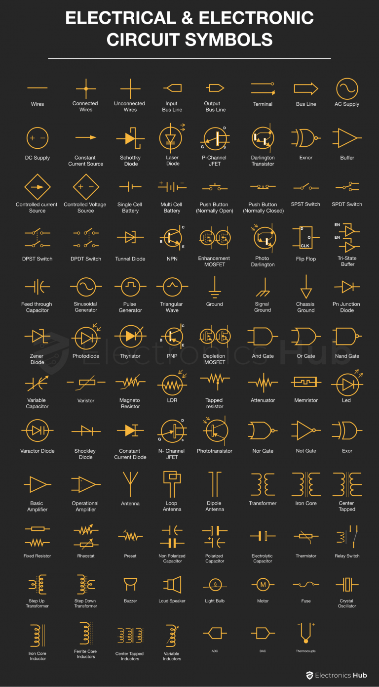
100+ Electrical & Electronic Circuit Symbols
100+ Electrical & Electronic Circuit Symbols
Electrical symbols or electronic circuits are virtually represented by circuit diagrams. There are some standard symbols to represent the components in a circuits.
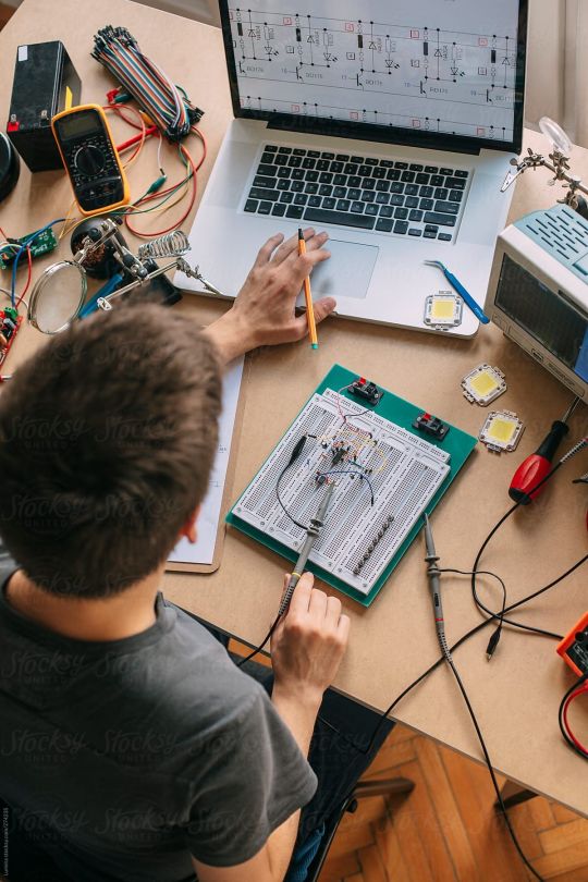
"Engineer Testing Electronic Equipment" by Stocksy Contributor "Lumina"
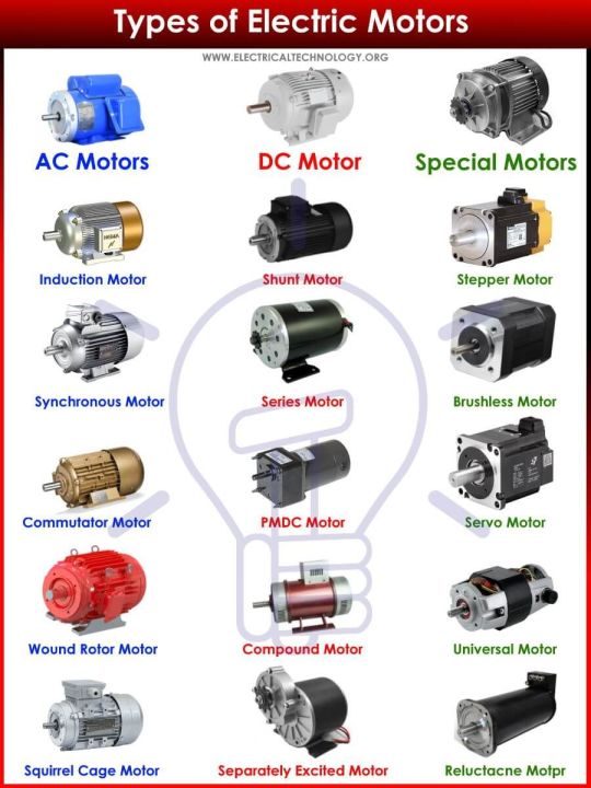
Types of Motors - Classification of AC, DC & Special Motors
Classification of Different Types of Electric Motors. AC and DC Motors, Special Motors. Synchronous & Asynchronous Motor. Induction Motors.
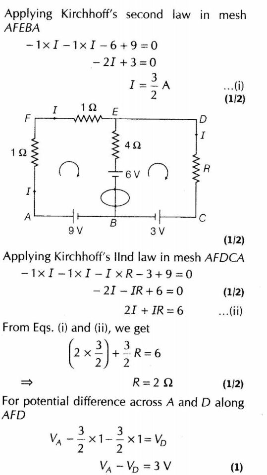
Important Questions for CBSE Class 12 Physics Kirchhoff's Laws and Electric Devices
Current Electricity Important Questions for CBSE Class 12 Physics Kirchhoff's Laws and Electric Devices
Edith Clarke
InStyle exclusively excerpts Rachel Ignotofsky's Women in Science—50 Fearless Pioneers Who Changed the World. The graphic hardcover is a must for any science lover.

Refunct Media 4 LEAP Berlin

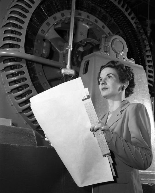
Kitty Joyner - Electrical Engineer
Description Kitty Joyner, electrical engineer, at Langley Research Center in 1952. Image Number: L-74800 Date: April 7, 1952

Electrical Engineer Gift Funny Engineering Sarcasm Sticker | Engineer
Electrical symbols or electronic circuits are virtually represented by circuit diagrams. There are some standard symbols to represent the components in a circuits. This article gives some of the frequently used symbols for drawing the circuits. There are many electrical and electronic schematic symbols are used to signify basic electronic or electrical device. These are mostly we used for draw circuit diagrams.Below are different kind of symbols we mentioned category wise. Hope this information will helps to understand clearly.Wires Switches Sources Ground Resistor Variable Resistor Capacitor Inductors Diodes Transistor Logic Gates Amplifiers Antenna Transformer Miscellaneous WIRES Wires Represents a conductor that conducts electrical current. Also called a power line or electric line or wire. Connected Wires Represents the connection of two conductors. Dot shows the junction point. Unconnected Wires Represents two unconnected wires/conductors. Input Bus Line Represents a bus for input or incoming data. Output Bus Line Represents a bus for output or outgoing data. Terminal Represents start or end point. Bus Line Represents a number of conductors joined together to form a bus wire. SWITCHES Push Button (Normally Open) This switch is in ON state when the button is pressed otherwise it is in OFF state. Push Button (Normally Closed) This switch is initially in ON state. This goes to OFF state when it is released. SPST Switch Single pole single throw is abbreviated as SPST. This acts as ON/OFF switch. Poles define the number of circuits it can be connected to and throws defines the number of positions that a pole connects. SPDT Switch Single pole double throw is abbreviated as SPDT. This switch allows the current to flow in any one of the two directions by adjusting its position. DPST Switch Double pole single throw is abbreviated as DPST. This switch can drive two circuits at a time. DPDT Switch Double pole double throw is the full form of DPDT. This can connect the four circuits by changing the position. Relay Switch This represents the relay switch. This can control the AC Loads using the DC voltage applied to the coil. SOURCES AC Supply This represents AC supply in the circuit. DC Supply This represents the DC power supply. It applies DC supply to the circuit. Constant Current Source The symbol represents an independent current source which delivers constant current. Controlled current Source It is a dependent current source. Usually depends on other sources (voltage or current). Controlled Voltage Source It is a dependent voltage source. Usually depends on other sources (voltage or current). Single Cell Battery This provides supply to the circuit. Multi Cell Battery Combination of multiple single cell batteries or a single large cell battery. The voltage is usually higher. Wave Generators Sinusoidal Generator Represents sine wave generator. Pulse Generator Represents pulse or square wave generator. Triangular Wave Represents triangular wave generator. GROUND SYMBOLS Ground It is equivalent to theoretical 0V and is used as zero potential reference. It is the potential of perfectly conducting earth. Signal Ground It is a reference point from which the signal is measured. There may be several signal grounds in a circuit due to the voltage drops in a circuit. Chassis Ground It acts as a barrier between user and the circuit and prevents electric shock. RESISTOR SYMBOLS Fixed Resistor It is a device that opposes the flow of current in a circuit. These two symbols are used to represent fixed resistor. VARIABLE RESISTOR Rheostat It is a two terminal variable resistor. They are generally used to control the current in the circuit. Generally used in tuning circuits and power control applications like heaters, ovens etc Preset It is a mini variable resistor. It is also called Trimmer Resistor or Trim Pot. The resistance is adjusted with rotary control present on top of it with the help of a screw driver. They are used to adjust the sensitivity of the circuit like temperature or light. Thermistor It is a temperature sensitive resistor. They are used in temperature sensing, current limiting circuits, over-current protection circuits etc. Varistor It is a Voltage Dependent Resistor. It has non-linear current-voltage characteristics. Generally used in circuit protection from voltage surges and excessive transient voltages. Magneto Resistor They are also called as Magnetic Dependent Resistors (MDR). The resistance of magneto resistor varies according to the external magnetic field strength. They are used in electronic compass, ferrous material detection, position sensors etc. LDR They are also called as Photo Resistors. The resistance of LDR varies with the intensity of the light incident on it. They are generally used in light sensing applications. Tapped resistor A wire-wound type fixed resistor with one or more terminals along its length. Generally used in voltage divider applications. Attenuator It is a device used to lower the power of a signal. They are made from simple voltage dividers and hence can be classified in the family of the resistors. Memristor The resistance of memristor is varied according to the direction of flow of charge. Memristors can be used in signal processing, logic/computation, non-volatile memory etc. CAPACITOR SYMBOLS Non Polarized Capacitor Capacitor stores the charge in the form of electrical energy. These two symbols are used for non-polarized capacitor. Non-polarized capacitors are big in size with small capacitance. They can be used in both AC and DC circuits. Polarized Capacitor Polarized capacitors are small in size but have high capacitance. They are used in DC circuits. They can be used as filters, for bypassing or passing low frequency signals. Electrolytic Capacitor Almost all electrolytic capacitors are polarized and hence used in DC circuits Feed through Capacitor They provide low impedance path to ground for high frequency signals Variable Capacitor The capacitance of the variable capacitor can be adjusted by turning the knob. They are widely used to adjust the frequency , that is for tuning. INDUCTORS Iron Core Inductor These are used as substitutes to ferrite core inductors. Ferrite core or Ferromagnetic inductors have high permeability and require air gap to reduce it. Iron powdered core inductors have this air gap integrated. Ferrite Core Inductors Core material, in this type of inductors is made of ferrite material. These are mostly used to suppress the interference of electromagnetic waves. Center Tapped Inductors These are used in coupling of signals, Variable Inductors Movable ferrite magnetic core variable inductors are most common. The inductance is varied by sliding the core in or out of the coil. DIODES Pn Junction Diode A PN junction diode allows the current to flow only in forward bias condition. These diodes can be used in clipping and clamping circuits , as rectifiers in dc circuits etc. Zener Diode In forward bias condition, it acts as normal diode and allows current. It also allows current to flow in reverse bias condition when the voltage reaches a certain break-down point. Generally used in voltage regulator and over voltage protection circuits. Photodiode Photodiode detects the light energy and converts it into current or voltage by a mechanism called photoelectric effect. These are used in CD players , Cameras etc. Led Light emitting diode is similar to PN junction diode but they emit energy in the form of light instead of heat. These are mostly used in indication , lightening applications. Varactor Diode Varactor diode is called varicap or variable capacitance diode. The capacitance of this diode varies according to the applied input voltage. This is used in frequency controlled oscillators , frequency multipliers etc. Shockley Diode This is a four layer diode. This had fast switching operation and hence is used in switching applications. Schottky Diode It represents Schottky diode. It has low forward voltage drop and it can switch rapidly. Used in voltage clamping, rectifiers, reverse current and discharge protection Tunnel Diode This is also known as Esaki diode.It can switch very fastly and can perform well in micro wave frequency range. This is used in oscillator circuits and micro wave circuits. Thyristor It consists of four layers of alternating P and N materials. They act as bistable switches and are used in circuits where high voltages and currents are involved. Constant Current Diode Also called as Current Limiting Diode or Current Regulating Diode. It limits the current to a specified maximum value. Laser Diode The laser diode is similar to light emitting diode. The active region is formed in intrinsic region in PIN structure. Laser diodes find its applications in laser printing, laser scanning etc. TRANSISTOR SYMBOLS NPN It is made of combination of P-type semiconductor between two N-type semiconductors. It is switched ON when the base-emitter junction is forward biased. They are commonly used for amplifying and switching applications. PNP It is made of combination of N-type semiconductor between two P-type semiconductors. It is switched ON when the base-emitter junction is reverse biased. These are used for amplifying and switching applications. JFET N- Channel JFET N-channel JFET is made by n-type silicon bars which form two PN junctions at the side. Majority charge carriers here are electrons. P-Channel JFET P-Channel JFET is made by p-type silicon bar which forms two PN junctions at the side. Majority charge carriers here are holes. MOSFET Enhancement MOSFET The enhancement mode MOSFET has positive gate operation. It induces negative charges into the n-channel and thus number of negative charges increases, enhancing the channel conductivity. Depletion MOSFET The depletion mode has negative gate operation. This decreases the width of the depletion layer. Phototransistor The photo transistor converts the light energy falling on it to its corresponding electrical energy. This can be used in light sensing applications.Base is left disconnected as light is used to enable the flow of current. Photo Darlington Photo Darlington Transistor is similar to phototransistor with very high gain and sensitivity Darlington Transistor This configuration produces high current gain. They are used in power regulators, output stages of audio amplifiers, display drivers etc. LOGIC GATES And Gate This is the basic gate and it implements logical conjunction. The output of the AND gate is high, only if both the inputs are high otherwise both are low. Or Gate The OR gate implements logical disjunction.The output is high if any one of the inputs is high. Nand Gate It is complement of AND gate. The output is low only when both the inputs are high, otherwise it is high. Nor Gate NOR gate is a not OR gate. Output of this gate is high, if both the inputs are Low, otherwise it is High. Not Gate Inverter or NOT gate implements logical negation. This gate inverts the input. Exor This gate implements exclusive OR logic. The output of this gate is high ,if both the inputs are different. Exnor This gate implements negation of EXOR logic. The output of this gate is high , only if the two inputs are identical. Buffer It is an audio signaling device. Generally used in alarms, timers and for confirmation messages. Tri-State Buffer Similar to a normal buffer but with a control signal. In case of active high buffer, it operates normally only when control signal is 1. In case of active low buffer, it operates normally only when control signal is 0. Flip Flop Flip flop is the alsoa memory element but this is a synchronous device. The figure below shows the basic D-flip-flop. AMPLIFIERS Basic Amplifier An amplifier is a device that amplifies a relatively small input signal i.e. it increases the power of the signal. They are used in communication systems, audio devices etc Operational Amplifier Operational Amplifier (Op Amp) is a voltage amplifier with very high gain. The input is differential. They are used in instrumentation devices, signal processing, control systems etc ANTENNA Antenna This symbol belongs to Aerial or Antenna. It converts electrical power into radio waves. It is used in wireless communication to transmit or receive the signals. Loop Antenna Loop antenna is named after its loop like shape of wire or other electrical conductor. They are used as receiving antennas in low frequency range. Dipole Antenna It is most widely used antenna.Generally used in set-top TV, shortwave transmission and FM receivers. TRANSFORMER Transformer Transformer is the basic element that transfers energy in one circuit to the other circuit through electromagnetic induction. They are generally used in electric power applications to increase or decrease the voltage of AC current. Iron Core Uses a piece of magnetic material as core. Generally Ferro magnetic metals like iron are used. The core has high permeability and is used to confine the magnetic field. Center Tapped The center tapped transformer has its secondary winding divided into two parts with same number of turns in each part. This results in two individual output voltages across two line ends. Used in rectifier circuits. Step Up Transformer The no. of turns in secondary winding is more than that of primary winding. The output voltage is higher than input voltage. Significantly used in inverters. Step Down Transformer The no. of turns in secondary winding is less than that of primary winding. The output voltage is lesser than input voltage. It is widely used in low power applications. MISCELLANEOUS Buzzer This is sound producing device. This produces buzz sound when the voltage is applied. Loud Speaker This is also an audio device. The electrical signal is converted into sound signal here. Light Bulb The symbol represents the light bulb. The bulb glows when required voltage is applied. Motor This converts the electric energy to mechanical energy. Fuse Symbol represents the fuse that protects the circuit from over current. Crystal Oscillator Used to generate clock signal of very precise frequency. ADC Analog to Digital converter is used convert analog signals (usually voltage) to digital values. DAC Digital to Analog converter is used to convert digital code to analog signals. Thermocouple It is used to measure temperature.
0 notes
Text
The Benefits of Using a DC DC Converter for Your Classic Car
Classic cars are a symbol of elegance and nostalgia, and they often come with unique electrical systems that require specialized components to keep them running smoothly. If you're the proud owner of a classic car, you may have encountered issues with your electrical system, such as dimming lights or weakened engine performance. In these cases, a 12V to 6V DC DC converter may be the solution you need.
A DC DC converter is a device that converts DC power from one voltage level to another, making it possible to use modern electrical components in older vehicles. The 12V to 6V DC DC converter, in particular, is designed to reduce the voltage from 12V to 6V, which is more suitable for classic car electrical systems. This device can help to restore the original performance and improve the reliability of your classic car's electrical system.
One of the biggest benefits of using a 12V to 6V DC DC converter is that it can reduce the stress on your classic car's electrical components. By reducing the voltage, the converter can prevent electrical components from overheating, which can cause damage and lead to system failure. This device can also help to extend the lifespan of your classic car's electrical components, so you can enjoy your ride for many years to come.
Both the 12V to 6V and the 12V to 24V DC DC converters are useful tools for classic car owners looking to improve the reliability and performance of their vehicle's electrical system. These devices can reduce stress on electrical components, enhance overall performance, and extend the lifespan of your classic car's electrical components. Whether you need to reduce the voltage from 12V to 6V or from 12V to 24V, these DC DC converters can provide a cost-effective solution to improve your classic car's electrical system. So, if you're looking to enhance your classic car's performance, consider investing in a 12V to 6V or a 12V to 24V DC DC converter. Visit our website www.hvmtech.com today for more information.
1 note
·
View note