#DHT11 Digital Temperature And Humidity Sensor
Explore tagged Tumblr posts
Visit Tumblr Blog
Explore Tumblr blogs with no restrictions, modern design and the best experience.
Last Seen Tumblr Blogs


Fun Fact
Tumblr has a 66 index score for customer satisfaction in the US.
Text
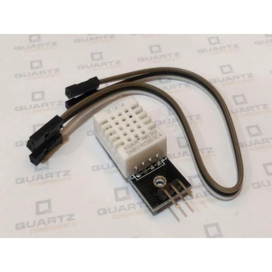
DHT11 Temperature and Humidity Sensor

The DHT11 Digital Temperature And Humidity Sensor is a basic, ultra low-cost digital temperature and humidity sensor. It uses a capacitive humidity sensor and a thermistor to measure the surrounding air and spits out a digital signal on the data pin (no analog input pins needed). Its fairly simple to use, but requires careful timing to grab data. The only real downside of this sensor is you can only get new data from it once every 2 seconds, so in your code please use sensor reading interval at 2 seconds or more. Compared to the DHT22, this sensor is less precise, less accurate and works in a smaller range of temperature/humidity. But despite its disadvantages over DHT22, it is smaller and less expensive sensor for temperature and humidity measurement.
Note: This package does not include Arduino board, you have to buy it separately.
Features:
Low power consumption.
Relative humidity and temperature measurement
All calibration, digital output
Excellent long-term stability
No additional components
Long distance signal transmission
Ultra-low power
4-pin package
Completely interchangeable
0 notes
Text
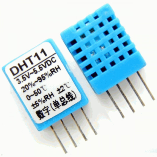
DHT11 Digital Temperature And Humidity Sensor is a basic and low-cost digital temperature and humidity sensor. This sensor is used for projects where accuracy and precision doesn't play big role. This comes in a blue perforated plastic enclosure. This has four pin. There is an upgraded version of the DHT11 temperature and humidity sensor available, which is DHT22 Sensor with higher sensing ranges.
2 notes
·
View notes
Text
Arduino Programming for Beginners: A Step-by-Step Guide
In the world of electronics and robotics, Arduino programming for beginners serves as an essential starting point for those eager to dive into the realm of microcontrollers and embedded systems. Arduino is an open-source platform that combines hardware and software, making it an ideal choice for newcomers. At Technobotics, we understand the importance of accessible and comprehensive learning resources for budding tech enthusiasts. This guide aims to provide a clear and straightforward introduction to Arduino programming for beginners.
What is Arduino?

Arduino is a microcontroller-based platform that allows users to create interactive electronic projects. The platform includes a programmable circuit board (microcontroller) and a software IDE (Integrated Development Environment) for writing and uploading code to the hardware. Arduino boards come in various models, such as the Arduino Uno, Arduino Mega, and Arduino Nano, each catering to different project requirements.
Getting Started with Arduino

1. Gather Your Components
To begin Arduino programming for beginners, you will need the following components:
An Arduino board (Arduino Uno is recommended for beginners)
USB cable to connect the Arduino to your computer
A computer with the Arduino IDE installed
Basic electronic components like LEDs, resistors, and breadboards
2. Install the Arduino IDE
The Arduino IDE is the software used to write and upload code to the Arduino board. It is available for Windows, macOS, and Linux. You can download it from the official Arduino website. Once downloaded, follow the installation instructions specific to your operating system.
3. Connect Your Arduino
Use the USB cable to connect your Arduino board to your computer. The power LED on the board should light up, indicating that the board is receiving power. Open the Arduino IDE and select the correct board and port from the 'Tools' menu.
4. Write Your First Program
In Arduino programming for beginners, the first program you usually write is the "Blink" program, which makes an LED blink on and off. Open the Arduino IDE, and you will see a blank sketch (a program written in the Arduino language).
Here is the "Blink" code:// the setup function runs once when you press reset or power the board void setup() { // initialize digital pin LED_BUILTIN as an output. pinMode(LED_BUILTIN, OUTPUT); }
// the loop function runs over and over again forever void loop() { digitalWrite(LED_BUILTIN, HIGH); // turn the LED on (HIGH is the voltage level) delay(1000); // wait for a second digitalWrite(LED_BUILTIN, LOW); // turn the LED off by making the voltage LOW delay(1000); // wait for a second }
5. Upload the Code
Click the 'Upload' button in the Arduino IDE to upload the code to your Arduino board. The onboard LED should start blinking, indicating that the code has been successfully uploaded and is running on the board.
Understanding the Code

In Arduino programming for beginners, understanding the basic structure of an Arduino sketch is crucial.
setup() function: This function runs once when the board is powered on or reset. It is used to initialize variables, pin modes, start using libraries, etc.
loop() function: This function runs continuously after the setup() function has completed. It is where the main logic of the program resides.
In the "Blink" example:
pinMode(LED_BUILTIN, OUTPUT); sets the LED pin as an output.
digitalWrite(LED_BUILTIN, HIGH); turns the LED on.
delay(1000); pauses the program for one second.
digitalWrite(LED_BUILTIN, LOW); turns the LED off.
delay(1000); pauses the program for another second.
Exploring More Projects

Once you are comfortable with the basics of Arduino advanced programming, you can explore more complex projects. Here are a few ideas to get you started:
1. Temperature and Humidity Monitor
Use a DHT11 sensor to measure temperature and humidity. Display the readings on an LCD screen. This project introduces you to using sensors and displaying data.
2. Motion Detector
Create a motion detector using a PIR sensor and an LED. When motion is detected, the LED will light up. This project helps you understand how to use sensors to trigger actions.
3. Servo Motor Control
Learn to control a servo motor using a potentiometer. This project is excellent for understanding how to read analog input and control output devices.
Troubleshooting Tips

As you delve into Arduino programming courses for beginners, you might encounter some common issues. Here are a few troubleshooting tips:
Board Not Recognized: Ensure the correct board and port are selected in the Arduino IDE.
Code Not Uploading: Check your USB connection and ensure no other program is using the same COM port.
LED Not Blinking: Double-check your code for errors and ensure the correct pin is being used.
Conclusion
Arduino programming for beginners is a rewarding journey that opens up endless possibilities for creating interactive electronic projects. At Technobotics, we are committed to providing you with the resources and support you need to succeed. Start small, experiment, and gradually take on more complex projects. Happy tinkering!
By following this guide, you will be well on your way to mastering the basics of Arduino programming and ready to explore the exciting world of electronics and robotics. For more tutorials and resources, visit our website and join our community of tech enthusiasts.
#robotics courses for kids#arduino advanced programming courses#arduino courses in mumbai#arduino programming courses#arduino programming for beginners
0 notes
Text
DIY: Build a Simple Arduino-based Weather Station for Your Mini Project in ECE
Weather forecasting is a critical part of many engineering projects. For example, in electrical engineering projects such as solar energy systems, wind turbines, and other renewable energy projects, understanding the local weather conditions is essential for accurate and reliable performance. As such, it is important for engineering students to be familiar with the basics of weather forecasting and to have access to a reliable weather station.
Fortunately, with the help of an Arduino microcontroller, it is possible to build a simple yet effective weather station for a mini project in electrical and computer engineering (ECE). This tutorial will walk you through the steps of setting up a basic weather station using an Arduino and some basic sensors.
The first step is to assemble the basic components of the weather station. This includes an Arduino board, a breadboard, a set of jumper wires, a temperature sensor (such as the TMP36), a humidity sensor (such as the DHT11), and an anemometer (such as the wind speed sensor).
The next step is to connect the components together on the breadboard. The temperature sensor should be connected to analog pin A0 on the Arduino, the humidity sensor should be connected to digital pin D2, and the anemometer should be connected to analog pin A1. The Arduino should also be connected to a power source, such as a 9V battery or USB power source.
Once the components are connected, the next step is to write the code for the Arduino. This code will read the data from the temperature, humidity, and anemometer sensors and display it on the Arduino's serial monitor. To do this, you will need to include the necessary libraries for the sensors in the Arduino software.
Once the code is written and uploaded to the Arduino, you can open the serial monitor and view the readings. You should see the temperature, humidity, and wind speed readings updating in real-time.
By connecting the Arduino to a computer, the readings can also be logged and monitored using specialized software such as ThingSpeak. This can be used to analyze the data and make predictions about the local weather.
By following the steps outlined in this tutorial, you can quickly and easily build a simple Arduino-based weather station for your mini project in ECE. With some basic knowledge of Arduino and programming, you can start gathering useful weather data quickly and easily.
0 notes
Photo

The project involves using an Arduino Nano to read data from a DHT11 temperature and humidity sensor and display that data on an LCD5110 display module. The DHT11 sensor uses a thermistor and a humidity sensing element to measure temperature and humidity, respectively. The sensor is connected to the Arduino Nano via a digital pin. The Arduino reads data from the sensor by sending a request signal, and the sensor responds with a data signal containing temperature and humidity readings. The LCD5110 display module is a monochrome LCD display that is commonly used with Arduino boards. It communicates with the Arduino via SPI (Serial Peripheral Interface) protocol, using five pins for communication: SCLK, DIN, DC, CS, and RESET. The Arduino Nano is programmed to read data from the DHT11 sensor and display that data on the LCD5110 display module. The Adafruit_PCD8544.h library is used to control the display, and the dht.h library is used to read data from the sensor. In the setup() function, the LCD display is initialized and the display contrast is set. The loop() function contains the main code for the project. It reads temperature and humidity data from the DHT11 sensor using the dht.h library, formats the data as a string, and displays it on the LCD5110 display using the Adafruit_PCD8544.h library. The display is updated every second to show the latest temperature and humidity readings. Overall, the project uses a combination of hardware and software to measure and display temperature and humidity data in real-time. (at Bangalore, India) https://www.instagram.com/p/CpM6Rw8LOQU/?igshid=NGJjMDIxMWI=
2 notes
·
View notes
Text
Data Science Vs Machine Learning And Synthetic Intelligence
The key here lies in the nature of the answer's predictive model. To be real AI, the predictive model needs to really be taught and enhance from its predictions. So, ask about how the machine learns when taking a look at predictive analytics solutions. Watson by IBM is a perfect example of how skilled techniques can benefit from the collaboration between deep learning, knowledge science, and AI. The laptop, which is powered by AI, can gather, take up, and process knowledge a lot faster than people.
apply modules for reusability and the object-oriented ideas for modeling and growing software program system. Functions, Overview, Defining a perform, Accessing a operate, Function prototypes, Passing arguments to a function, Passing arrays to functions, Recursion. decompose an issue into capabilities and synthesize an entire program utilizing divide and conquer strategy.
Introduction to interrupts, Multiple interrupts, Introduction to cache reminiscence, Elements of cache design, Internal Memory, Semiconductor memory, Error correction, Advance DRAM. learn about the working of processor, primary reminiscence, and control unit. develop software program options utilizing multi-threading, networking and client-server ideas.
IBM Cloud Pak for Data Meet your organization’s ever-changing needs with this totally built-in data and AI platform. IBM Watson® Studio Build and scale trusted AI on any cloud. Introduction to exterior gadgets, Input / Output modules, Programed I/O, Interrupt driven I/O, Direct memory access, I/O channels and processors, introduction to course of scheduling.
First, you'll usually hear individuals speak about predictive analytics, or analytics where a machine is using historic data to forecast the long run. AI powers many refined predictive analytics options, so if you see the term, you could be looking at AI. And "deep studying" is the most advanced type of machine learning, the place neural nets are structured to mimic the human brain. The solely compulsory element within the second yr is the Master’s thesis.
Machine studying delivers correct results derived by way of the analysis of massive information sets. Applying AI cognitive technologies to ML techniques can end result in the effective processing of information and knowledge. But what are the key differences between Data Science vs Machine Learning and AI vs ML?
Data science is far more than simply simple machine learning. Data here may not have been obtained via a machine, and it could not even be for studying purposes. Put, knowledge science tends to cover the whole spectrum of knowledge processing as we know it.
Split-testing occurs, then the machine learns on its own what to improve based mostly on the outcomes. Over time, the machine will get higher and better with little human involvement. This unlocks possibly unlimited efficiency potential. and stochastic processes are fundamental areas within the information science and AI master’s programme. The courses included in the programme plan deal with matters such as machine studying, databases and algorithms. AMachine LearningEngineer is an avid programmer who helps machines perceive and decide up knowledge as required.
To interface DHT11 sensor with Arduino/Raspberry Pi and write a program to print temperature and humidity readings. To interface Push button/Digital sensor (IR/LDR) with Arduino/Raspberry Pi and write a program to show ON LED when push button is pressed or at sensor detection. perceive professional ethics and organizational culture conduct in info expertise. develop programming expertise to unravel real time computational problems. The Master of Artificial Intelligence and Data Science course addresses this transformation by providing you as a pupil with the broad and in-depth expertise required to work with and develop AI. You shall be educated the way to acquire, course of and retailer huge amounts of information, which is the foundation of AI and growth processes.
In reality, AI exists at present that may help you get much more worth out of the data you have already got, unify that knowledge, and really make predictions about customer conduct based on it. You want to select a minimum of two programs from the final group 1 and at least two from the profile particular group 2. You can then specialize on one of many profile tracks. In the second yr you have to full a grasp's thesis value 30 credits to be able to graduate.
Explore more on - data science course in hyderabad with placements
360DigiTMG - Data Analytics, Data Science Course Training Hyderabad
Address:-2-56/2/19, 3rd floor, Vijaya towers, near Meridian school, Ayyappa Society Rd, Madhapur, Hyderabad, Telangana 500081
Contact us ( 099899 94319 )
https://360digitmg.com/data-science-course-training-in-hyderabad
Hours: Sunday - Saturday 7 AM - 11 PM
0 notes
Text
DHT11 digital temperature and humidity sensor/temperature and humidity sensor/temperature and humidity transmitter/probe
DHT11 digital temperature and humidity sensor/temperature and humidity sensor/temperature and humidity transmitter/probe

lastest_volume
0
Just For Today
Click Here To Visit The Shop
N€W DHT11 digital temperature and humidity sensor/temperature and humidity sensor/temperature and humidity transmitter/probe
0 notes
Text
DHT22 Temperature and Humidity Sensor
DHT22 is the upgraded version of the DHT11 temperature and humidity sensor. It uses a capacitive humidity sensor and thermistor based temperature sensor to measure the ambient humidity & temperature. The humidity sensing ranges from 0% to 100% with ±1% accuracy and the temperature sensing ranges from -40 degrees to the 80 degrees Celsius with ±0.5°C accuracy. The sampling time of this sensor is 2 seconds almost.
DHT22 Sensor Specifications
Operating Voltage: 3.5V to 5.5V
Digital I/O
5 Hz sampling rate (Once every 2 Seconds)
Measuring current: 0.3mA
Low power consumption
Temperature range: -40 to 80 degree C
Humidity range: 0% to 100%
Accuracy: ±0.5°C and ±1%
Dimension: 5x 4 x 2 cm
Buy this Temperature and Humidity Sensor: https://quartzcomponents.com/products/dht22-temprature-and-humidity-sensor-module
0 notes
Text

DHT11 Temperature and Humidity Sensor
The DHT11 Digital Temperature And Humidity Sensor is a basic, ultra low-cost digital temperature and humidity sensor. It uses a capacitive humidity sensor and a thermistor to measure the surrounding air and spits out a digital signal on the data pin (no analog input pins needed). Its fairly simple to use, but requires careful timing to grab data. The only real downside of this sensor is you can only get new data from it once every 2 seconds, so in your code please use sensor reading interval at 2 seconds or more. Compared to the DHT22, this sensor is less precise, less accurate and works in a smaller range of temperature/humidity. But despite its disadvantages over DHT22, it is smaller and less expensive sensor for temperature and humidity measurement.
Note: This package does not include Arduino board, you have to buy it separately.
Features: -Low power consumption. -Relative humidity and temperature measurement -All calibration, digital output -Excellent long-term stability -No additional components -Long distance signal transmission -Ultra-low power -4-pin package -Completely interchangeable
0 notes
Text
DHT11 Digital Temperature And Humidity Sensor is a basic and low-cost digital temperature and humidity sensor. This sensor is used for projects where accuracy and precision doesn't play big role. This comes in a blue perforated plastic enclosure. This has four pin. There is an upgraded version of the DHT11 temperature and humidity sensor available, which is DHT22 Sensor with higher sensing ranges.
The sensor uses a capacitive humidity sensor and a thermistor based temperature sensor to measure the ambient humidity and temperature. The humidity sensing ranges from 20% to 90% with ±5% accuracy and the temperature sensing ranges from 0 degrees to the 50 degrees Celsius with ±2°C accuracy. The sampling time of this sensor is 2 seconds almost. This Temperature and Humidity Sensor uses digital pins to communicate with the microcontroller unit and does not have any kind of analog pins.
2 notes
·
View notes
Text
ESP8266 DIY IoT Wetterstation mit OLED Display und DHT11 Sensor

In diesem Beitrag möchte ich dir die DIY IoT Wetterstation mit dem Microcontroller ESP8266, einem OLED Display sowie dem DHT11 Sensor vorstellen.

DIY IoT ESP8266 Wetterstation
Bezug
Diese kleine Wetterstation mit dem ESP8266 Microcontroller habe ich über aliexpress.com für ca. 7€ inkl. 4€ Versandkosten erstanden. Auf ebay.de erhälst du diesen Bausatz für ca. 17€ inkl. Versandkosten. Da beide Produkte aus dem asiatischen Raum geliefert werden, denke ich das die Lieferzeit ziemlich ähnlich sein werden und somit empfehle ich das deutlich günstigere Produkt von aliexpress.com. Lieferumfang Zum Lieferumfang gehört: ein 30cm langes USB Kabel (USB Typ A Stecker auf Micro USB Buchse), eine Hauptplatine mit dem ESP8266 Chip, ein 0,96" OLED Display, ein DHT11 Sensor, sowie 3 Breadboardkabel, 20cm, Buchse - Buchse (zum alternativen Anschluß des DHT11 Sensors) Geliefert wurde das Display sowie der Sensor in jeweils kleine, antistatische Tüten.

Lieferumfang, DIY IoT Wetterstation Die Hauptplatine wurde zusammen mit dem USB Kabel in einer kleinen Plastikbox geliefert, welche jedoch so groß ist dass, das Display und der Sensor einen Platz darin finden. Leider kann diese Box aber nicht als Gehäuse für diesen Bausatz verwendet werden da der DHT11 Sensor knapp 2cm zu hoch absteht.

Aufbewahrungsbox für die Bauteile zur DIY IoT Wetterstation
Zusammenbau der Komponenten
Dieser kleine und vor allem sehr übersichtliche Bausatz (3 Bauteile) wird über Stiftleisten und Buchsen zusammengesteckt. Der DHT11 Sensor ist dabei fertig aufgebaut und wird in die 3 Polige Buchse oben rechts gesteckt. Es ist dabei auf die korrekte Polung zu achten. An das Display muss die vierpolige Stiftleiste angelötet werden, ich stecke dazu diese Stiftleiste auf ein Breadboard und fixiere das Display mit UHU patterfix.

"Board:" > "Boardverwalter...") öffnet kann man den Treiber unter der Eingabe der Zeichenkette "esp8266" installieren.

Boardverwalter - ESP8266 Treiber In meinem Fall ist dieser bereits installiert. benötigte Bibliotheken Für die Programmierung des Sketches / Programmes benötigen wir 3 Bibliotheken, zwei für das Display und eine für den DHT11 Sensor. Für das OLED Display verwende ich die Adafruit GFX und Adafruit SSD1306 Bibliothek. Beide Bibliotheken findest du im Bibliotheksverwalter der Arduino IDE. Den Boardverwalter öffnest du in dem du über das Hauptmenü "Sketch" > "Bibliothek einbinden..." > "Bibliotheken verwalten..." navigierst. Dort gibst du nun die Zeichenkette "gfx" ein und suchst nach dem Eintrag "Adafruit GFX Library" und installierst diese über die Schaltfläche "Installieren". Das gleiche machst du ebenfalls mit der Bibliothek "ssd1306" (der Eintrag lautet "Adafruit SSD1306"). Wenn beide Bibliotheken installiert sind wird als letztes die Bibliothek für den DHT11 Sensor installiert. Hier gibt es diverse Bibliotheken ich verwende die "DHT sensor library" von Adafruit. Es ist nach der Installation kein neustarten der Arduino IDE notwendig, die Treiber und Bibliotheken sind sofort Einsatzbereit. Ausgabe der Sensordaten auf dem Display //Bibliothek für die Kommunikation über I2C #include //Bibliothek für den Sensor DHT11 #include "DHT.h" //Bibliotheken zum betreiben des Displays #include #include //Der DHT11 Sensor ist am Board über den //digitalen Pin D5 angeschlossen #define DHTPIN 5 //Der Sensor ist vom Typ DHT11 //Theoretisch könnte man den DHT11 auch gegen einen //DHT22 oder ASM2320 austauschen, diese Sensoren sind //baugleich #define DHTTYPE DHT11 //erstellen einer Instanz des Sensor Objektes DHT dht(DHTPIN, DHTTYPE); //default Rest des Displays #define OLED_RESET 4 //eine neue instanz für das Display erzeugen Adafruit_SSD1306 display(OLED_RESET); void setup() { //beginn der seriellen Kommunikation mit 9600 baud //eventuelle Fehler (zbsp. beim lesen der Werte des DHT11 Sensors) //werden auf der seriellen Schnittstelle ausgegeben Serial.begin(9600); //beginn der Kommunikation mit dem DHT11 Sensor dht.begin(); //setzen der I2C Pins auf digital D2 und digital D14 Wire.begin(2,14); //beginn der Kommunikation mit dem Display //das OLED Display verfügt über die Adresse 0x3C display.begin(SSD1306_SWITCHCAPVCC, 0x3C); //setzen der Textgröße auf den kleinsten Wert von 1 display.setTextSize(1); //setzen der Schriftfarbe "weiß" display.setTextColor(WHITE); } void loop() { //eine Pause von 2 Sekunden delay(2000); //lesen der rel. Luftfeuchtigkeit float h = dht.readHumidity(); //lesen der Temperatur in Grad Celsius //mit der übergabe des Parameters "false" in der Funktion //readTemperature(), wird der Wert in Grad Fahrenheit geliefert float t = dht.readTemperature(); //prüfen ob Zahlenwerte geliefert wurden //Wenn der Sensor nicht gefunden wurde, dann enthalten die flaot Variablen "NaN" if (isnan(h) || isnan(t)) { Serial.println(F("Fehler beim lesen der Sensorwerte!")); return; } //löschen des Displays display.clearDisplay(); //setzen des Cursors an die Position Spalte = 0, Zeile = 0 display.setCursor(0, 0); //schreiben der Temperatur, //der Wert der Variable t wird dabei in ein String umgewandelt und //auf zwei Stellen nach dem Komma gekürzt. display.println("Temp.: " + String(t,2)+"C"); //setzen des Cursors an die Position Spalte = 0 , Zeile = 15 display.setCursor(0, 15); //schreiben der rel. Luftfeuchtigkeit //der Wert der Variabel h wird dabei in ein String umgewandelt und //auf zwei Stellen nach dem Komma gekürzt. display.println("Humidity: "+String(h,2)+"%"); //aktualisieren des Displays display.display(); } Read the full article
0 notes
Link
Recomended Products

Component listing: 1pcs UNO R3 Controller Board 1pcs LCD1602 Module ( with pin header) 1pcs Breadboard Expansion Board 1pcs Power Supply Module WARNING: Pls. do not use the voltage higher than 9V 1pcs Joystick Module 1pcs IR Receiver 1pcs Servo Motor (SG90) 1pcs Stepper Motor 1pcs ULN2003 Stepper Motor Driver Board 1pcs Ultrasonic Sensor 1pcs DHT11 Temperature and Humidity Module 1pcs 9V Battery with DC 1pcs 65 Jumper Wire 1pcs USB Cable 1pcs Active Buzzer 1pcs Passive Buzzer 1pcs Potentiometer 1pcs 5V Relay 1pcs Breadboard 1pcs Remote 1pcs Tilt Switch 5pcs Button (small) 1pcs 1 digit 7-segment Display 1pcs 4 digit 7-segment Display 5pcs Yellow LED 5pcs Blue LED 5pcs Green LED 5pcs Red LED 1pcs RGB LED 2pcs Photo resistor 1pcs Thermistor 2pcs Diode Rectifier (1N4007) 2pcs NPN Transistor (PN2222) 1pcs IC 74HC595 120pcs Resistor 10pcs Female-to-male DuPont Wire. Free PDF tutorial(more than 22 lessons) and clear listing in a nice package Free PDF tutorial(more than 22 lessons) and clear listing in a nice package The most economical kit based on Arduino platform to starting programming for those beginners who are interested. Free PDF tutorial(more than 22 lessons) and clear listing in a nice package Free PDF tutorial(more than 22 lessons) and clear listing in a nice package The most economical kit based on Arduino platform to starting programming for those beginners who are interested. Lcd1602 module with pin header (not need to be soldered by yourself) Free PDF tutorial(more than 22 lessons) and clear listing in a nice package Free PDF tutorial(more than 22 lessons) and clear listing in a nice package The most economical kit based on Arduino platform to starting programming for those beginners who are interested. Free PDF tutorial(more than 22 lessons) and clear listing in a nice package Free PDF tutorial(more than 22 lessons) and clear listing in a nice package The most economical kit based on Arduino platform to starting programming for those beginners who are interested. Lcd1602 module with pin header (not need to be soldered by yourself) This is the upgraded starter kits with power supply module, 9V battery with dc Free PDF tutorial(more than 22 lessons) and clear listing in a nice package Free PDF tutorial(more than 22 lessons) and clear listing in a nice package The most economical kit based on Arduino platform to starting programming for those beginners who are interested. Free PDF tutorial(more than 22 lessons) and clear listing in a nice package Free PDF tutorial(more than 22 lessons) and clear listing in a nice package The most economical kit based on Arduino platform to starting programming for those beginners who are interested. Lcd1602 module with pin header (not need to be soldered by yourself) Free PDF tutorial(more than 22 lessons) and clear listing in a nice package Free PDF tutorial(more than 22 lessons) and clear listing in a nice package The most economical kit based on Arduino platform to starting programming for those beginners who are interested. Free PDF tutorial(more than 22 lessons) and clear listing in a nice package Free PDF tutorial(more than 22 lessons) and clear listing in a nice package The most economical kit based on Arduino platform to starting programming for those beginners who are interested. Lcd1602 module with pin header (not need to be soldered by yourself) This is the upgraded starter kits with power supply module, 9V battery with dc High quality kite with UNO R3. 100% compatible with Arduino UNO R3, MEGA 2560 R3, NANO.
0 notes
Text
Weather Monitoring System Using Internet of Things - Juniper publishers
Journal of Trends in Technical and Scientific Research
Abstract
In this research, a foundation is set for an efficient solution for tracking the weather conditions of a specific location and making the information available anywhere in the world. The technological advances behind this is Internet of Things (IoT), which is an efficient and effective solution for linking the things to the web and to connect the entire world of things in a network. Here things could be like electronic gadgets, sensors, and automotive electronic devices. The system functions with tracking and monitoring environmental circumstances such as temperature, relative humidity, light intensity, pressure and quantity of rainfall with sensors and whenever these scores exceed a selected threshold limit for each an e-mail, an SMS alerts the appliance owner to take the required steps
Keywords: Smart Environment; Internet of Things Weather Monitoring System Cloud
Introduction
Present technological innovations focus primarily on managing and tracking various operations. To achieve human needs, these are increasingly emerging. To monitor and evaluate the circumstances in case of exceeding the prescribed level of parameters (e.g. noise, gas and radiation levels), an effective environmental monitoring system is needed. When objects such as environment embedded with sensor devices, microcontroller and multiple software applications become an environment of self-protection and self-monitoring, it is also called a smart environment. In such an environment the alarm or LED alerts automatically occur when some incident happens. The impacts on livestock, crops and humans due to the environmental modifications can be tracked and regulated by a smart monitoring system for the environment. By making the environment interactive with other objectives by using embedded intelligence, this is one of the applications that targets smart environment. Human needs are dependent on the type of information collected by the sensor devices, different kinds of monitoring systems. The two categories to which applications are categorized are based on event detection and spatial process estimation. Initially, sensor systems are implemented in the environment to detect parameters (e.g., temperature, humidity, pressure, LDR, noise, CO and radiation levels, etc.) while acquiring, computing and controlling information (e.g., noise and gas levels variations in the specified levels).Sensor devices are positioned at various places to gather information to predict the behavior of a specific area of interest. Here Internet of Things (IoT) is the concept of linking all the sensors to the internet [1]. The primary purpose of this document is to develop and execute an effective monitoring system whereby the necessary parameters are remotely controlled using the internet and the information collected from the sensors are stored in the cloud and analyzed there and then an email, an SMS alerts whenever the threshold limit exceeds [2].
Materials and Methods
Problem Statement
The satellite weather reporting system provides the current condition that does not give the exact location condition. The drawbacks are in conventional approach where the devices are costly and have no visualization of information. There is no such automatic tool to offer the alert signal in case of any abnormalities, so it is difficult to regulate this abnormality
Proposed Model
Weather conditions are tracked in the home’s external environment or any buildings and information are transferred to the cloud server. The benefits will be that this system will manually transmit the real-time environment information. It is possible to view the information in any part of the world. This application isto monitor and update the condition of the surroundings regularly. Conditions of the environment can be tracked by gathering the data from the sensors and deposited in the cloud and analyzed there and then an email, an SMS alerts if the situation of the environment becomes abnormal.
Environment Monitoring System
An IOT application is used to monitor the environment that helps monitor the environmental condition of any local area or a surrounding area, and with the help of the internet everyone can view the condition. This application is more efficient, quicker in offering conditions for the environment [3]. It enables people or government to take remedial action if the environmental condition becomes abnormal. Environmental condition monitoring system offers a technique for verifying the condition and changes occurs over the surrounding. In this system we use Arduino, sound sensor, gas sensor, temperature sensor, moisture sensor, pressure sensor, IOT module. The humidity and temperature sensor will track climate change and provide information. It is helpful for agriculture [4]. To monitor pollution over the atmosphere, the gas and sound sensor are used. Currently, pollution from air and noise makes the environment more susceptible. Using this module, we can identify the polluted area and expressly create people’s consciousness for living in the pollution. Changes in the climate system cannot be accurately defined and sometimes accidentally defined, but with the help of an IOT module we can characterize more approximate changes in an environment and update them in the cloud. This system uses many modules as follows:
Sensor Module:
The sensor network is linked to a hefty amount of small sensor nodes that can be used as an effective tool for collecting information for different applications under different situations [5,6]. Different sensors are integrated into this study that has its distinctive way of collecting information from the surroundings. An integrated circuit sensor (LM35) used to evaluate temperature with an electrical output proportional to the temperature (in oC). If the temperature goes up, the fan is going on and vice versa. The factor of scale is .01V / oC. The LM35 requires no external calibration or trimming and retains a +/-0.4oC accuracy at room temperature and +/-0.8oC over 0 oC to+ 100 oC range.
System utilizes moisture sensors DHT11. It provides outstanding quality, quick response, capacity to prevent interference, and cost-effectiveness. On the calibration of humidity, this sensor is highly precise.
MQ-6 gas sensor’s sensitive material is SnO, which has lower conductivity in clean air. The MQ-6 gas sensor is highly sensitive to Propane, Butane and LPG, as well as natural gas response. The Sensor could be used to detect various fuel gases, particularly methane; it is appropriate for separate applications at a low price.
The sound sensor module offers a straight-forward sound monitoring technique and is generally used for sound power detectiondetection. This module can be used for apps for safety and tracking. Its precision for comfort of use can be readily adapted.
The BMP180 is an I2C standard device and a pressure sensor. It’s a 4-pin tool, i.e., SDA, SCL, VIN, GND. The connection between Vin and GND is 3.3V and GND. SDA connects to the nodemcu D2 pin and SCL connects to the nodemcu D3 pin.
Power Module:
The Power for the system can be provided via the adapter or the USB. Use the USB cable or an external power supply to power the Arduino board. Source of power can be selected automatically.
Controller Module:
This implementation is controlled by Arduino UNO. The Arduino board transforms to digital data the analog data produced by the sensor. Arduino is generated to monitor or comprehend the environment or surroundings by receiving feedback from a variety of sensors and can impact its atmosphere by controlling lights, engines, and other actuators. The board’s microcontroller is programmed using the Arduino programming language and Arduino development environment. Arduino projects can be separated or when operating on a desktop they can interact with software.
IoT Module:
The IoT board is intended to satisfy a range of online application demands with different benefits that allow the embedded system designer to readily, rapidly and seamlessly add internet connectivity to their applications. The module’s UART update feature and webpage management make them excellent for online wireless applications like environmental sensors and information from moveable battery-operated wireless sensor network devices. Lumisense IoT board is designed with SIM900 GPRS modem for active internet connection so that it is equipped with a controller for processing all UART data based on GPRS online data.
Light Dependent Resistor (LDR):
An LDR is a light-controlled variable resistor. The LDR’s strength is reduced by the increasing light intensity falling on it. It has an analog output that is an input to the nodemcu’s A0 pin.
Raindrop Module:
It is used for rain detection. It can also be used to measure rain intensity. It has both digital and analog output. This module analyses the moisture by means of analog output pin and gives a digital output when the moisture limit exceeds too much. The more water or less resistance implies the reduced voltage of the output. Whereas, the less water implies higher resistance, i.e, high output voltage on the analog pin. For instance, a totally dry board will result in five volts of module output. The module’s analog output is linked to the nodemcu’s A0 pin.
Working of the Analog Pin (A0):
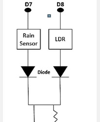
The Nodemcu board has only 1 analog pin, but two analog output devices, viz, LDR and Raindrop module, are multiplexed to the A0 using two diodes in this project. The circuit of multiplexing is shown in Figure 1 below. Here the Raindrop Vcc sensor is connected to the nodemcu D7 and the LDR input is connected to the nodemcu D8. When D7 is high, D8 is low, making LDR off and module raindrop on. Thus,the raindrop sensor output reaches the nodemcu A0 through the diode. Similarly, when D8 is high and D7 is low, the LDR is on and the raindrop module is off creating a route for the LDR output to achieve the nodemcu A0 through the second diode.
Execution
Arduino is driven by a USB cable and the four sensors are linked to the Arduino board and the information collected from the sensors is stored in the cloud and analyzed there and then an email, an SMS alerts whenever the threshold limit exceeds. The IoT module is also linked to the Arduino board to receive feedback from the sensors and is driven by the adapter. The USB cable givespower to the Arduino board and then transfers information from Arduino board to the computer
Results
Once the sensor measures are downloaded to the cloud, the values are evaluated and then the threshold limit exceeds an e-mail, an SMS and a tweeter post are posted. Some findings of the study are as follows Figures 2 & 3.
Algorithm 1:Analog Pin Multiplexing Input: LDR D8, raindrop D7; Output: Analog pin A0 loop { if (digitalRead(D7) == HIGH) { A0=raindrop sensor value; digitalWrite(D7, LOW); } else if (digitalRead(D8) == HIGH) { A0=LDR value; digitalWrite (D8, LOW); } }
Algorithm 2:E-mail, SMS Input: temp, humidity, press, LDR, rain; Output: email, sms loop { temp=temperature value measured; humidity=humidity value measured; press=pressure value measured; LDR=light intensity measured; rain=rain value measured; if (temp && humidity && press && LDR && rain) { publish all the measured value to the cloud bluemixserial.println(temp); serial.println(humidity); serial.println(press); serial.println(LDR); serial.println(rain); } else { serial.println(” error! check the sensors.”); } if(temp>=40) { email=” The current temperature is” + temp; sms=” The current temperature is” + temp; } if(humidity>=50) { email=” The current humidity is” + humidity; sms=” The current humidity is” + humidity; } if(rain>=200) { email=” It’s raining outside. Bring your umbrella”; sms=” It’s raining outside. Bring your umbrella”; } if(LDR>=150) {post only once in a day { email=” Good Morning”; sms=” Good Morning”; } } }
Conclusion
This System monitors the changes happening over the environment and provides enough ways for the users to access the information from anywhere through cloud. The temperature and humidity sensor will monitor and gives the details about the changes happening over the climate. The gas and sound sensor are used for monitoring the pollution over environment. The Monitored condition will be updated in the cloud.
To Know More About Trends in Technical and ScientificResearch Please click on: https://juniperpublishers.com/ttsr/index.php
To Know More About Open Access Journals Please click on: https://juniperpublishers.com/index.php
#Juniper Publishers#Open Access Journals#Juniper publisher reviews#Peer review Journals#Scientific research
0 notes
Text
The Final Project
The Aim
The aim of this project is to connect the LEDs, the temperature sensor and the heat mat in the same circuit and create a code that can utilise the functionality of every individual component working together.
The first aim is to use 3 different LEDs (2 yellow and 1 red) which would turn on and off individually depending on the temperature
The second aim is to implement the unsoldered heat mat in the circuit without bottlenecking the current flow
The third aim is to turn on and off the heat mat depending on the temperature to make sure that the reptile enclosure is starting to heat up if the temperature is below the optimal point. I would also like to turn off the heat mat if the temperature is too high for the reptiles that way they are not overheated.
Components Used
This experiment consisted of the most components so far and while there are alternatives to these components, any component used of the same type will be able to work as long as it is implemented in the code correctly.
Arduino Leonardo
DHT11 Temperature and Humidity Sensor
3 LEDs
4 Resistors
A Heat Mat
A Mosfet
A Diode
LCD screen
Hardware Setup
To connect all the components together, we first have to supply the breadboard with an electrical current (5 volt pin from the Arduino) and also ground it to make a complete circuit.
The second step is to add the DHT11 sensor to the circuit and also connect it to an analog pin which we once again used the A0 pin for. To make things easier, i connected the DHT11 directly to the Arduino’s 5 volt, ground and A0 pins rather than having it run inside the circuit to see if it still works.

I then added 3 LEDS to the breadboard circuit by giving them electricity through the 5volt circuit we have created and grounding them once again through the circuit. Last but not least, the LEDs would have to be manipulated in the code so i connected them to the 9,10 and 11 digital pins respectively. A resistor for each LED was also used to prevent them from being burned

Lastly, I connected the unsoldered heat mat to the Mosfet’s ground pin via male to female wires and the 5 volt wire of the heat mat directly to the bread board circuit. The other two pins of the Mosfet were connected to a grounding spot in the circuit and a space on the breadboard which connected directly to pin 2 on the Arduino.


Once i tested that everything was working, i also implemented the LCD screen to the circuit and also included the soldered heat mat


The breadboard circuit was enough to provide the 5volt power the LCD required and i also grounded the LCD through the circuit. Lastly, i connected the SDA and SCL pins from the LCD to the SDA and SCL pins on the Arduino.
Software Setup
To add functionality to the experiment we had to first use the following libraries:
“LiquidCrystal_I2C” to implement functions regarding the LCD
“Wire” to communicate with the I2C attached to the LCD
“dht” to implement functions regarding the temperature sensor

We also defined the temperature sensor to the analog pin we have it connected to using the “#define”
Afterwards, i created the variables which i will be using these were composed of the 3 integer variables i have used for the LEDs set to the digital pin number they are connected to, the fetPin variable which is equal to the pin number the heat mat/mosfet is connected to, a variable named dht to help us manipulate the temperature and a liquid crystal library variable named “lcd” to manipulate the LCD screen later on.

Moving on to the setup, i set the LCDs’ screen specifications using the lcd.begin() function from the library and also used the wire.begin() function to be able to use the I2C interface. I also configured the 3 individual LEDs as output devices by entering the pin they are connected to using the variables created earlier. Similarly, i configured the heat mat pin as an output device using the variable created to enter the pin it is connected to. In the final 3 lines of the setup, i initiated the LCD screen and turned on its’ backlight using the functions provided by the library followed by a 1 second delay

Last but not least, in the loop section, i first set up the functionality of the temperature sensor and the LCD by first reading the temperature and humidity data using the DHT11 read function from the library, setting the cursor on the first character of the first and second row and printing messages for the humidity and temperature along with their correct units of measurement and displaying the data received from the DHT11 sensor to the LCD screen.

Once that was working and displaying the temperature data on the LCD screen, i created an if statement, an “else if” statement and an “else” statement which with the conditions that the current temperature was either higher than 30 degrees celsius, lower than 14 degrees celsius or between 14 and 30. Depending on the temperature the two yellow lights would be on and the red light would be off, all the lights would be on or none of the lights would be on. To do this i used the digital write function and added the name of the variable for each LED along with the state i would like the to be in depending on the conditions of the statements.
To turn on the heat mat at different temperatures i used the “analogWrite” function instead since we are using an analog connection, used the variable i created which holds the pin number the MOSFET is connected to and set a different value depending on if i wanted the heat mat to be off, at full power or around half power.

The Final Product
I have also included a video of me explaining the functionality of the final product. Since the potentiometer was connected directly to the LCD screen, no code was used to adjust the brightness of the display.
youtube
The Code
#include <LiquidCrystal_I2C.h> #include <Wire.h> #include "dht.h" #define dht_apin A0
int yellow_light_pin = 11; int red_light_pin = 10; int yello_light2_pin = 9; int fetPin = 3; dht DHT; LiquidCrystal_I2C lcd(0x27,16,2); void setup(){ lcd.begin(16,2); Wire.begin(); pinMode(red_light_pin, OUTPUT); pinMode(yellow_light_pin, OUTPUT); pinMode(yellow_light2_pin, OUTPUT); pinMode(fetPin , OUTPUT ); lcd.init(); lcd.backlight(); delay(1000);
}//end "setup()"
void loop(){ //Start of Program
DHT.read11(dht_apin); lcd.setCursor(0,0); lcd.print("Humid. = "); lcd.print(DHT.humidity); lcd.print("%"); lcd.setCursor(0,1); lcd.print("Temp. = "); lcd.print(DHT.temperature); lcd.print("C");
if(DHT.temperature>30){ analogWrite(fetPin,0); //lcd.println("The heat mat is off"); digitalWrite (yellow_light2_pin, LOW); digitalWrite (yellow_light_pin, LOW); digitalWrite (red_light_pin, LOW); }else if (DHT.temperature<14){ digitalWrite (red_light_pin, HIGH); digitalWrite (yellow_light_pin, HIGH); digitalWrite (yellow_light2_pin, HIGH); analogWrite(fetPin,255); //lcd.println("The heat mat is on at 100% power"); }else{ digitalWrite (yellow_light_pin, HIGH); digitalWrite (red_light_pin, LOW); digitalWrite (yellow_light2_pin, HIGH); analogWrite(fetPin,140); //lcd.println("The heat mat is on at 66% power");
} delay(15000);
}// end loop()
References
https://astronomersanonymous.wordpress.com/2016/04/02/controlling-heating-pads-with-arduino-uno/
https://learn.sparkfun.com/tutorials/heating-pad-hand-warmer-blanket/all
0 notes
Text
RFID Starter Kits For Arduino R3 Upgraded Version Learning Suite Module Board With Retail Box

https://sensoq.com/product/rfid-starter-kits-for-arduino-r3-upgraded-version-learning-suite-module-board-with-retail-box/ Learning Video Material: http://pan.baidu.com/share/link shareid=3613634125&uk=2500272204 Package Included: 1 x R3 1 x USB cable 1 x HC-SR04 ultrasonic sensor 4pin 1 x HC-SR501 PIR motion sensor module 1 x 30 line 1 x 830 points breadboard 30 x Led (red, green, yellow) 40 x Resistance (220R, 330R, 10K, 1K) 1 x 10 pin DuPont line 1 x Potentiometer 1 x Activity buzzer 1 x Passive buzzer 1 x 74HC595N 1 x Infrared receiver 1 x LM35DZ 1 x Flame sensor 2 x Ball switch 3 x 5mm LDR 5 x Push button switch with cover 1 x Infrared remote control 1 x Digital tube 1 x Four digit digital tube 1 x 8 * 8 dot matrix tube 1 x UNL2003 driver board 1 x 5V stepper motor 1 x SG90 1 x LCD1602 IIC I2C 1 x PS2 game joystick module 1 x DHT11 temperature and humidity sensor module 1 x water level measurement module 1 x RFID module 1 x RFID key ring 1 x RFID card 1 x Sound sensor module 1 x One way relay module 1 x RTC module 1 x16 key matrix keyboard module 1 x2.54mm 40pin connector 1 x 9V battery clip Sensoq.com
Read More >>>
https://sensoq.com/product/rfid-starter-kits-for-arduino-r3-upgraded-version-learning-suite-module-board-with-retail-box/
0 notes