#DIYElectronics
Explore tagged Tumblr posts
Visit Tumblr Blog
Explore Tumblr blogs with no restrictions, modern design and the best experience.
Last Seen Tumblr Blogs


Fun Fact
12.7% of mobile users access Tumblr.
Text
Solenoids go clicky-clacky 🔩🔊🤖
We're testing out an I2C-to-solenoid driver today. It uses an MCP23017 expander. We like this particular chip for this usage because it has push-pull outputs, making it ideal for driving our N-channel FETs and flyback diodes. The A port connects to the 8 drivers, while the B port remains available for other GPIO purposes. For this demo, whenever we 'touch' a pin on port B to ground, the corresponding solenoid triggers provide an easy way to check speed and power usage.
#solenoid#electronics#i2c#mcp23017#hardwarehacking#maker#embedded#engineering#robotics#automation#circuitdesign#pcb#microcontroller#tech#hardware#diyelectronics#electricalengineering#firmware#innovation#prototype#electromechanical#diy#electronicsproject#smarthardware#tinkering#gpio#fet#flybackdiode#programming#linux
44 notes
·
View notes
Text
Built your Raspberry Pi Kiwix Hotspot or have questions? Share your experiences or tips in the comments below! Let's learn together.
#DigitalDivide#DigitalEquity#diy wikipedia#DIYElectronics#DIYTech#EdTech#educational technology#InformationAccess#Kiwix#kiwix setup#KnowledgeForAll#offline internet#offline library#OfflineData#OfflineFirst#OfflineLearning#OpenSource#preparedness#prepper tech#PrepperTech#raspberry pi#raspberry pi kiwix hotspot#raspberry pi projects#RaspberryPi#TechGuide#TechProjects#zim files
2 notes
·
View notes
Text
How to Use AHT10 High Precision Digital Temperature & Humidity Sensor with Arduino
Looking to measure temperature and humidity with high accuracy using Arduino? The AHT10 sensor is a compact, I2C-based module that provides reliable data, making it perfect for IoT projects, weather stations, and smart home automation.
What You’ll Learn: ✔️ How the AHT10 sensor works ✔️ Wiring it to an Arduino board ✔️ Writing & uploading the code to get readings ✔️ Tips for stable and accurate measurements
What You Need:
AHT10 Temperature and Humidity Sensor Module
Arduino Nano
0.96 inch SSD1306 OLED Display (128x64, I2C)
Breadboard
Connecting/Jumper Wires
Arduino Nano Cable
Download the Code & Library Arduino AHT10 Temperature and Humidity Sensor Module
Watch the full tutorial on YouTube:
youtube
Follow for more DIY electronics tutorials & Arduino projects!
3 notes
·
View notes
Text
Super Tiny RP2040/ESP32 Display Development Board
Compact RP2040/ESP32 Powered Display board with Type-C connector, keeps it up to date, easier to use
Support us on Kickstarter today

2 notes
·
View notes
Text
DIY Dumble-like sounding MOSFET Overdrive

The Hermida Zendrive guitar pedal we will study, assemble and listen to today is a true masterpiece. Many say its sound is close to the Holy Grail of guitar amplification - Dumble Overdrive Special.
Other people are more pessimistic in their judgments. Still, the precise response to the picking dynamics, the Voicing tuning options, and the sheer beauty of this overdrive's sound are simply impossible not to love.
But before we study the Lovepedal Zendrive or its copy of the Landtone Phoenix song, or the Aion effects Azimuth dynamic overdrive, we'll study the evolution of the MOSFET overdrives that finally resulted in the development of this gem.
Fulltone OCD

Mike Fuller was one of the first to start using MOSFETs instead of diodes to limit the amplified guitar signal in 2004.
His Obsessive-Compulsive Drive overdrive-distortion pedal is built on a standard circuit with one dual op amp. The first operational amplifier, X1, amplifies the amplitude of the guitar signal by a factor from 8 to 463 times, depending on the position of the drive control X3. This is a 1-megohm potentiometer.

Further, through resistor R9, the signal is fed to the limiter, which comprises 2N7000 MOSFETs M1 and M2 connected in parallel. A germanium diode D1 - 1N34A is additionally included in series with M2, which makes the limiter asymmetrical and, therefore, makes more interesting sound.
A limiter in overdrives is usually included in the negative feedback circuit of an operational amplifier (i.e., in parallel with C6). Such a limiter is called a soft limiter.
And here, a hard limitation is applied: clipping sections are included between the preamplifier output of the gain section and the virtual ground - half of the supply voltage Vref, formed by resistors R4 and R7.
Virtual ground is used in the unipolar powering of operational amplifiers to amplify analog signals, such as audio signals. The guitar signal does not change from zero to plus but from minus to plus, passing through zero.
To prevent the signal from being limited to the circuit's ground, it is shifted in the plus direction by half the supply voltage.
Such hard limiting is typical for distortion pedals. But by using MOSFETs instead of diodes or LEDs, the top of the signal is not cut hard but softly rounded. Therefore, OCD can work as both distortion and overdrive.
Due to the smoothed peaks of the limited signal, the sound is highly dependent on the sound's attack dynamics. For rock and especially blues, this is very valuable. With modern metal pickups that compress the dynamic range of the signal, it can help make solos sounding more sweet.
The second operational amplifier X3 amplifies the limited signal by a factor of 3.8, correcting its timbre. Capacitors C6 and C9 prevent the self-excitation of operational amplifiers at high frequencies.
Next is a simple passive tone knob, which implies a treble leak circuit. Potentiometer X4 10 kilohms and capacitor C11 47 nanofarads are connected in the same way as on the pickguard of any electric guitar.
The Switch1 switch changes the circuit's output impedance as if the high-impedance and low-impedance pickups were switched. When it's open, you get a transparent overdrive like the Klon Centaur, and when it's closed, you can get a more aggressive sound like the Marshall Plexi.
Hermida Audio Zendrive

The Zendrive pedal's authors, Hermida audio technology (now produced by LOVEPEDAL LLC), have undoubtedly studied the Fulltone OCD thoroughly. Let's find the differences between the two circuits.
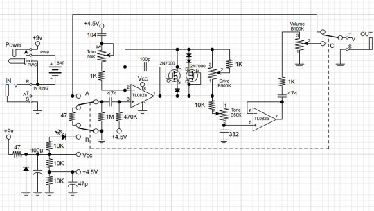
First, the limiter is included in the operational amplifier feedback, that is, between the output and the inverting input, not between the output and virtual ground. That is, here we have a soft limiter.
Secondly, one diode is added in series with each MOSFET. Clipping remains asymmetric: we have one diode in the left arm of the limiter and two diodes in the right arm.
Third, the second operational amplifier is used as a voltage repeater, aka buffer: the output is directly connected to the inverting input.
Fourth, the tone control is implemented a little differently: two OCD`s switchable resistors are replaced by a potentiometer.
And finally, the most critical, fifth difference. A potentiometer is included in the tone correction circuit between the inverting input of the first operational amplifier and the artificial midpoint.
This fourth knob, Voicing, or Character, allows you to smoothly adjust the lower frequencies in the overdrive structure over a wide range, similar to the Resonance control on many tube guitar amps.
The potentiometer is signed as a trimmer in the diagram because some pedal makers don't want to install a fourth knob on the pedal`s body. This is what Landtone did when developing the Phoenix Song Overdrive DIY kit.
The developer suggests installing the trimmer on the PCB, and to access it, you need to disassemble the pedal by unscrewing the footswitch nut and taking out the PCB.
But I will not be lazy to drill an extra hole in the pedal body and install a potentiometer with a knob, connected to PCB by wires instead of the trimmer. Because I consider this regulator simply invaluable and irreplaceable.
Before we get to assembly and testing, let's look at another pedal with a similar adjustment. However, it is based not on the Fulltone OCD but on the Ibanez Tube Screamer.
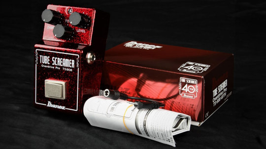
The Precision Drive

This is a signature pedal by Misha Mansour of Periphery, manufactured by Horizon Devices. Compared to the original Overdrive Pro TS808, the circuit adds a noise suppressor, which we will not consider, and an exciting ATTACK switch.
The Precision Drive scheme was studied and partially replicated by PedalPCB and PCB Guitar Mania. They are manufacturers of DIY kits for guitarists. Their products are called Dwarven Hammer and Collision Drive, respectively. A noise gate is not provided there, but the attack switch is implemented. This is the main difference between Precision Drive and many other overdrive pedals.

In the Fulltone OCD schematic, we saw a resistor switch at the tone shaping circuit in the output section. The Zendrive has a variable resistor in the preamp's RC circuit which is controlling the overdrive structure.
Precision Drive has a constant resistor in the same place, between the inverting input of the overdrive section operational amplifier and the virtual ground, but the capacitors are switched.
This is the same thing: we change the time constant of the RC circuit, which adjusts the audio signal's frequency spectrum. At the same time as the time constant, the complex impedance changes, thus the gain.
A resistor is a resistance to both DC and AC current. At the same time, a capacitor is only resistant to AC current because DC current does not flow through a capacitor. Since DC current does not flow through our RC circuit, there is no difference between adjusting the resistance and switching the capacitance.
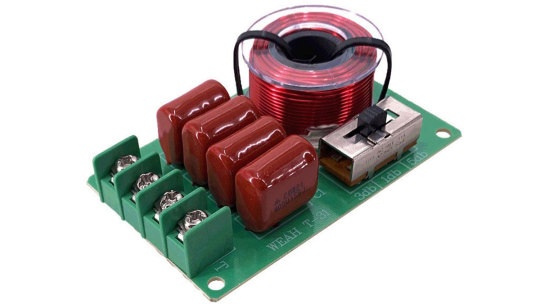
But the active/reactive ratio affects the circuit's Quality factor, i.e., its resonance. It's no coincidence that the knob on guitar amplifiers, which adjusts the same frequencies as our potentiometer or switch, is often called RESONANCE. And it is used to adjust to the resonance of the electromechanical system - the loudspeakers in the cabinet, along with the masses of air in and around it.
The reactive impedance accumulates energy and gives it away, except for losses due to dielectric recharging and magnetizing the magnetic core in inductors. This is why coreless inductors are often used in high-end equipment, so-called air inductors. They weigh a lot, take up a lot of space, and are expensive because copper is more expensive than steel. But these are the laws of physics on which technology is based.
Unlike reactive impedance, active resistance converts electrical energy into heat, thus reducing the Q-factor. In some cases, it is necessary and useful. In others, it is harmful. Or it simply creates a unique sound character.
That's why switching capacitors and turning the potentiometer knob in the feedback circuit of an audio frequency amplifier is almost the same thing, but not quite. And it's great that there are such different variants of guitar overdrive pedals!
Landtone Phoenix Song Overdrive
Now you can hear how my Zendrive from the Landtone OD-1 kit sounds, with a Seymour-Duncan SH4 humbucker on a Gibson MM Explorer guitar, into an Orange MT20 with a Torpedo Captor X. And see how I assembled the pedal and also a kitten walking around the table and prancing around.
youtube
I liked the pedal, especially its fourth magic Voicing knob, which does things to the sound that other tone controls can't. I also liked the bird on the body. Because I love birds. And in the music world, the decoration of instruments and hardware plays no small role because it inspires creativity. And the fact that the pedal is assembled by my hands also warms my soul and creates inspiration.
3 notes
·
View notes
Text
The idea is for people who live with someone, and this someone does not know how to knock on the toilet door to check if it is occupied!!!
This is a simple device based on some kind of microcontroller that turns on the red backlight along the contour of the door if the latch is closed, and turns on the green backlight when the latch is open. The latch in this case works as a switch, and the microcontroller checks whether there is power on the pin connected to the latch and thus knows which backlight to turn on.
As a result, we get a demonically red illuminated door that hates this someone who does not know how to knock on this very door!
Even If I dont make it myself, I'll post everything you need for this project.
#demonic door will come to you while you asleep#tech#shittertonpost#diyelectronics#diy tutorial#diy#house idea
2 notes
·
View notes
Text
Get better performance and reliability with MTK International's premium copper cables. Our cables are made from only copper material and are designed to maximize conductivity and durability in applications from commercial and residential to industrial power distribution. We offer a wide variety of cable types you'll need to meet international standards, making sure some level of efficiency and safety is included in every installation. From flexible cable to multi-core to armored copper cable, MTK International is the premium copper cable solution for your project. We know our stuff and can provide you with the best 'power' for your installations using our copper cables - delivering reliability and precision. Take a look at MTK International's quality copper cabling solutions, combined with high-level engineering.
#CopperCables#ElectricalWiring#CableManagement#DIYElectronics#HomeWiring#TechTips#Conductivity#ElectricalEngineering#WireConnections#IndustryStandards#SustainableTech#ElectricalProjects#CopperWire#CableInstaller#Electronics#Innovation#CablingSolutions#DIYProjects#SmartHome#WiringDiagrams
0 notes
Text
Soldering Station and Tips in India: A Complete Guide for Professionals
Soldering is a crucial process in electronics manufacturing, repair, and DIY projects. Whether you're an engineer, technician, or hobbyist, having the right soldering station and tips in India can make a significant difference in precision, efficiency, and safety.
Why Choose a Quality Soldering Station in India?
A reliable soldering station in India ensures: ✔ Temperature Control – Prevents overheating of sensitive components. ✔ ESD-Safe Operation – Protects static-sensitive devices. ✔ Durability – Long-lasting performance for industrial use. ✔ Versatility – Compatible with different soldering tips for various tasks.
Types of Soldering Stations Available in India
Basic Soldering Irons – Affordable and suitable for beginners.
Temperature-Controlled Stations – Ideal for professionals requiring precision.
Digital Soldering Stations – Offer LCD displays for exact temperature settings.
Rework Stations – Used for PCB repairs and SMD components.
Choosing the Right Soldering Tips in India
Soldering tips come in various shapes and sizes, each designed for specific tasks:
Chisel Tip – Best for general soldering.
Conical Tip – Ideal for precision work.
Bevel Tip – Great for drag soldering.
Knife Tip – Used for SMD components.
High-quality soldering tips in India ensure better heat transfer, longer lifespan, and reduced oxidation.
Top Brands for Soldering Stations and Tips in India
Hakko – Known for professional-grade soldering stations.
Weller – Offers reliable and durable soldering solutions.
Vastar – Budget-friendly options for hobbyists.
Aoyue – Popular for rework and repair stations.
Maintenance Tips for Soldering Equipment
Clean tips regularly with a brass sponge.
Use flux to improve solder flow.
Store tips properly to prevent oxidation.
Replace worn-out tips to maintain efficiency.
Where to Buy Soldering Stations and Tips in India?
You can find high-quality soldering stations and tips in India on:
ascompinc.com
#SolderingStation#SolderingTips#ElectronicsTools#DIYElectronics#PCBRepair#EngineeringTools#SolderingIndia#TechTools#ElectronicsHobbyist#ProfessionalSoldering
0 notes
Text
5A Adjustable Power Adapter Buying Guide – Features, Uses & Tips

A 5A adjustable power adapter provides flexible voltage control, making it suitable for various electronic devices. It ensures stable power output, preventing damage to sensitive equipment. Look for features like over-voltage protection and compatibility with multiple devices for optimal use.
#5AAdapter#AdjustableAdapter#PowerAdapter#VariablePowerSupply#DCAdapter#UniversalAdapter#PowerSolutions#ElectronicsAccessory#TechGadget#VoltageControl#SmartAdapter#ChargingSolution#PowerSupply#DIYElectronics#Callsa#CallsaAdapter#CallsaChargers#CallsaPower#CallsaElectronics#CallsaInnovation
0 notes
Text

A behind-the-scenes look at real-time hardware development. This setup features hands-on circuit prototyping using breadboards, jumper wires, LED modules, and PCB components. From testing connections to debugging circuits, it’s all about turning ideas into working electronic devices—one connection at a time.
#ElectronicPrototyping#HardwareDevelopment#CircuitDesign#PCBDesign#TechInProgress#EmbeddedSystems#PrototypeToProduct#ElectronicsLab#MakersMovement#DIYElectronics#TechInnovation#IoTDevelopment#EngineeringInAction#BreadboardBuilds
0 notes
Text

Newxie brings the joy of nixies without the 170V power supply 💡🕰️✨
If there's one thing that melts our hearts, it's a nixie clock - we built one 20 years ago!
but nixies are hard to find now that we don't hit up the MIT swapfest at 7am anymore
well we saw this funky faux nixie clock
http://www.unitedcreation.co/marvel-tubes/
and realized they're just using the same 1.14" TFTs we stock already
so why not re-spin the breakout into a skinny right-angle-mount version? Instead of card edge, we have 2x7 right angle headers - both rows are the same contact, but this way, we get more mechanical stability. We kept the level shifting to work with 3.3V or 5V microcontrollers but dropped the micro SD card. You could stack these side by side on a breadboard with as little as 0.7" pitch!
#nixieclock#electronics#makercommunity#arduino#tftdisplay#creativeprojects#vintagestyle#retrodesign#diyelectronics#makersgonnamake#openhardware#engineeringfun#microcontrollers#electronicsprojects#techhacks#techinnovation#mitcommunity#geeklife#retroaesthetic#buildcoolstuff
39 notes
·
View notes
Text

ICStation's New RGB Dimmer Light Soldering Kit! ✨🌸Combine learning and creativity with this flower-shaped DIY project. Perfect for soldering practice, STEM education, or adding a vibrant decorative touch to your space!
💡 Adjust the RGB lighting effects to suit your mood or style. A fun, educational, and rewarding project for all ages!
0 notes
Text

LCD Display modules are commonly used in most of the embedded projects to display various output data. It's cheap, handy, and programmer-friendly for various DIY projects. The Alphanumeric Graphical LCD (2004A) is a 20x4 Liquid Crystal Display that comes in blue or green colors. It can show four lines of text, with each line holding up to 20 characters making a total of 80 characters to be displayed on screen. This is larger than the 16x2 LCD, but the programming is similar. The display is used to show a wide range of things like text, characters, numbers, and symbols.
7 notes
·
View notes
Text


Badtiming at the Quip & Curiosity, Cambridge.
Tues 29th October 2024 - 7-10pm
A night of improvised noise and full frequencies, sonic experiments and inventions.
Delighted to have played alongside "there are no birds here" and "Tom Daley".
www.bad-timing.co.uk
Special thanks to Jo for the invitation.
Photo Credit: @DShappyBOI / Callis
#dushume#noise#liveelectronics#noisemusic#soundart#harshnoise#experimentalsound#glitch#noiseselector#diynomad#Cambridge#quip&curiousity#Badtiming#Harshbass#DeepNoise#diyelectronics#bassshaker#bassculture#soundartist#experimentalmusic#electronicmusic#experimentalnoise
0 notes
Text
youtube
...In which I demonstrate my mods for the Boss MT-2 Metal Zone, specifically the no-solder mods to remove the hardwired gyrator EQs that are responsible for so much of the pedal's inherent sound, plus a couple of bonus mods I did to my personal unit. Enjoy!
0 notes
Text
How does logic work? Decoders and Demultiplexers

Greetings to all the fans of microcontrollers and digital chips! Today, we will get acquainted with decoders and demultiplexers that allow one to expand microcontroller ports, transfer a lot of data over a few wires, create stunning lighting effects, and much more.

In the post about the CD4017 decimal counter-decoder, we've put together the running fire effect. The chip counted from zero to nine and lit the corresponding LED, which created a nice, dynamic image.

The picture becomes even better, more dynamic, and more varied if you take two CD4017s: one lighting the LEDs horizontally and the other vertically.

Today's scheme of ring running lights is different from the previous one, firstly, as the CD4017 is clocked not by the NE555 timer but by a symmetrical transistor multivibrator.

The multivibrator consists of two stages with a common emitter on transistors Q1 and Q2. These two stages are exactly the same, making the multivibrator symmetrical.
The input of each stage is connected to the output of the other through an electrolytic capacitor.
A capacitor stores electrical charge. The voltage between the plates of a capacitor is proportional to the charge (in coulombs) it has accumulated.
The larger the capacity, the more charge the capacitor needs to accumulate for the voltage across it to increase by one volt. For example, 1 microfarad means that charging a capacitor at 1 volt requires 1 microcoulomb of electricity.
Resistors limit the current. The current through a resistor equals the voltage divided by the resistance. For example, at a voltage of 1 volt, a current of 1 milliamp flows through a resistor with a resistance of 1 kilohm.
Current refers to the amount of electricity passing through a conductor, resistor, or anything else per unit of time. One milliamp is equal to one millicoulomb per second.
So, a capacitor with a capacity of 1 microfarad will charge or discharge 1 volt with a current of 1 milliamp in one millisecond. And a current of 1 milliamp will flow through a resistor with a resistance of 1 kilohm if the voltage across the resistor is 1 volt.
You can see where I'm going with this: capacitors and resistors can set the time and, accordingly, the frequency of oscillations if we have a threshold element that switches at a certain voltage value.
In our multivibrator, the role of these elements is played by transistors. For the bipolar transistor to open, current must flow through the base. And for current to flow, the voltage between the base and emitter must reach the direct drop level at the p-n junction.
Now, let's see how we have the LEDs hooked up. Each of the ten channels is designed the same way. To avoid unnecessary clutter, the diagram shows just one.
When the voltage level at the Q0 output of the CD4017 chip is high, the electrolytic capacitor C3 is quickly charged through the diode D1 to a voltage just below the voltage of the power supply. Transistor Q3 opens, and LED1 and LED2 get lit.
At the start, Q3 is in saturation mode, and the current through the LEDs is determined by the resistance of resistor R6; the voltage across it is equal to the supply voltage minus the sum of the LEDs' operating voltage and the transistor's UCE.
When the next clock pulse arrives from the multivibrator, the logical one moves to the following output of the CD4017 microcircuit. Subsequently, a logical zero appears at its output Q0. Still, capacitor C3 can't discharge through diode D1 because the diode does not conduct current in the opposite direction.
However, C3 is gradually discharged through resistor R7 by the base current Q3. This current is equal to the difference in voltage across C3 and Ube of transistor Q3 divided by the resistance R7.
As capacitor C3 discharges, the voltage across it decreases gradually, and the base current decreases accordingly. As soon as the product of the base current and the transistor current gain h21e becomes lower than the current through resistance R7, the collector current, also known as the LED current, will begin to decrease.
Thus, each LED flashes brightly and then dims down to zero when C3 discharges to voltage Ube and the transistor turns off.
Depending on the clock frequency, tuned by variable resistor R4, the LED will go out completely or continue to glow dimly until a complete counting cycle has passed, and the circuit that lights this LED has again reached a logical one.
In the video example, I've been using different color LEDs, which glowed with varying brightness levels and went out at different speeds.
youtube
The following circuit does almost the same thing but with a few quirks.

First, instead of the decimal CD4017 counter, I used binary CD4060. It is already familiar to us since I devoted a separate post.
The CD4060 has a built-in clock generator, which requires only one capacitor and two resistors to operate. Therefore, this circuit does not need a transistor multivibrator or NE555.
To get running lights, we need a decoder that, at b000 at the input, will light the zero LED, at b001—the first, at b010—the second, and so on, up to the seventh LED at 111.
The 74HC138 chip, a 3:8 binary decoder-demultiplexer, executes this function in our circuit.

Each of the 3-input AND gates processes possible combinations from 000 to 111. To handle logic zeros, inputs have inverters.
The outputs of the microcircuit are also connected through inverters. So, unlike the CD4017, where a logic one moves between ten outputs, the 74HC138 will have a low level at the output, corresponding to the input value, and the other seven outputs will be high.
Or all eight outputs could be high if the decoder is disabled. For the decoder to work, inputs ¬G0 and ¬G1 must have logic zeros, and G2 must have one.
From the counter outputs Q7, Q8, and Q9, numbers from b000 to b111 are supplied to the decoder data inputs A0, A1, and A2. And the signal from Q10 is supplied to the control input E3.
It turns out that the LED lighting cycles will alternate with empty cycles when pulses are not supplied to the LED control units, and the brightness gradually decreases.
Please note that here, we have the chip facing the diode's cathode and not the anode. Transistors use PNP structures, which are opened with a negative signal, rather than NPN, which is opened with a positive one.
The electrolytic capacitor here is charged by the base current of the transistor and discharged through the diode and the chip's output. As you can see, this upside-down scheme also works.

The program memory controller in our homemade processor unit was the 4:16 74HC154 decoder-demultiplexer. It differs from the 74HC138 in one additional input bit. This doubles the number of outputs!
Multiplexers can be cascaded. Two 74HC154s will make a 5:32 decoder. This would take four 74HC138 chips to perform the same function.

The three least significant bits, N0, N1, and N2, are equally supplied to the inputs of both decoders. And the most significant bit turns off the first decoder and turns on the second.
This means that values from b0000 to b0111 are handled by eight corresponding outputs of the first chip, and from b1000 to b1111, the second one comes in with its eight lines.
Those simple means help us perform different tasks provided by trusty logic chips.
0 notes