#Magnetic stator assemblies
Explore tagged Tumblr posts
Visit Tumblr Blog
Explore Tumblr blogs with no restrictions, modern design and the best experience.
Last Seen Tumblr Blogs


Fun Fact
25% of US internet users with an annual income of $80-100K use Tumblr.
Text
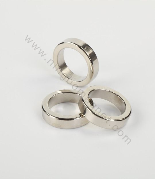
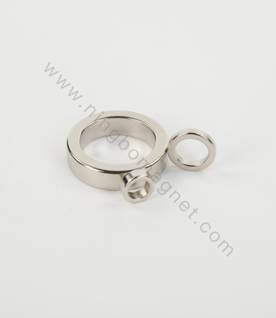
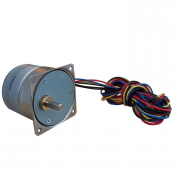
Magnetic Stator Assemblies
Magnetic stator assemblies is also a representatives magnetic assembly,consisting of housing and permanent magnet which similar like magnetic rotor assembly. Permanent magnets are mounted on the housing, then housing working as the magnetic yoke to a form a magnetic circuit.

Contact With Us Call Anytime: +86-191 0672 9372 Send Email: [email protected]
0 notes
Text
Torque test of Magnetic Coupling
[email protected] WhatsApp: 0086 15257962734 www.wallymagnet.com
#magnet#permanent magnets#holding magnet#pot magnet#hook magnet#magnetic assembly#magnetic coupling#inner rotor#out stator
0 notes
Text
What You Need to Know About Arc Segmentitle Magnets, Radial Axial Circle Magnets, Isotropic and Anisotropic Magnets
Magnets serve an important part in a variety of sectors today, including electric motors, generators, sensors, and magnetic assembly. Among the several varieties available, the Arc Segmentitle Magnet, Radial Axial Circle Magnet, and the distinction between Isotropic and Anisotropic Magnets stand out for their performance, shape, and magnetic qualities. But what do these phrases signify, and where do these magnets usually appear?
What is an Arc Segment Magnet?
An Arc Segment Magnet—an arc or segment magnet—is commonly employed in circular magnetic assemblies, notably brushless DC motors and permanent magnet motors. These magnets are shaped like a circle slice and are intended to be used around a rotor or stator.
Important characteristics:
Accurate curvature for a snug radial fit
Available in a variety of materials, such as ferrite, samarium cobalt, or neodymium (NdFeB).
Perfect for spinning systems with high speeds
High concentration of magnetic flux along the arc
Common Applications:
Drones and e-bikes with electric motors
Windmills
Couplings of magnets
Industrial robotics and servo motors
What Is a Radial Axial Circle Magnet?
A magnet with a circular or ring form with a magnetic direction that is either axial or radial is called a radial-axial circle magnet. The distribution of the magnetic field is determined by these orientations. In precision equipment, a radial-axial circle magnet is frequently specially made to meet certain torque or sensing requirements. Their specialized magnetic orientation and round shape guarantee little energy loss and excellent performance.
What Makes an Isotropic Magnet Different from an Anisotropic One?
Although materials like ferrite, neodymium, or rare earth compounds may be used to create both isotropic and anisotropic magnets, there are major differences in their production procedures and performance.
Conclusion
Knowing the differences between arc segmental magnets, radial axial circle magnets, and anisotropic / Isotropic Anisotropic Magnet magnets is essential for improving both your design and performance, whether you're an engineer creating the next high-efficiency motor or a manufacturer locating dependable magnetic components. Every magnet design and kind offers a unique set of benefits. Selecting the best one requires finding the ideal balance between cost-effectiveness, application fit, and magnetic strength.
Follow our Facebook and Twitter for more information about our product.
2 notes
·
View notes
Text
Premium Neodymium Magnet Solutions
Understanding the Role of Neodymium Magnets
Neodymium magnets are widely recognized as the most powerful type of permanent magnets available today. They are extensively used in industries such as electronics, automotive, renewable energy, and medical equipment due to their exceptional strength and compact size. As demand grows for high-performance magnet solutions, the need for a reliable Neodymium Ring Magnet Supplier and Neodymium Arc Magnet Supplier has become more important than ever.
Why Quality Magnet Suppliers Matter
Sourcing neodymium magnets from a trusted supplier ensures consistency in magnetic performance, dimensional accuracy, and coating durability. A professional supplier adheres to stringent quality standards and offers tailored magnet designs to fit specific industrial applications. For instance, a dependable Neodymium Ring Magnet Supplier can provide various grades and sizes suitable for applications like loudspeakers, sensors, and medical instruments where circular magnetic fields are crucial.
Similarly, choosing a specialized Neodymium Arc Magnet Supplier is essential for applications in motors and generators. Arc magnets must fit precisely into stators and rotors, requiring not only strong magnetic properties but also high mechanical precision. Suppliers with advanced manufacturing capabilities and a deep understanding of magnetic field dynamics can deliver arc segments that enhance the efficiency and lifespan of electric motors.
Custom Solutions for Diverse Industries
Neodymium magnets are not one-size-fits-all. Each industry requires specific shapes, grades, and surface coatings. A seasoned Neodymium Ring Magnet Supplier understands these needs and can customize dimensions, magnetization directions, and protective coatings such as nickel, epoxy, or gold to suit the environment in which the magnet will function.
When it comes to motor production and other high-performance applications, the support of a Neodymium Arc Magnet Supplier becomes vital. These magnets, usually embedded in brushless motors or wind turbines, must be designed with tight tolerances and high corrosion resistance to ensure long-term stability. Reliable suppliers work closely with engineers and manufacturers to ensure the magnets meet both technical and operational requirements.
The Importance of Technical Expertise
Technical guidance is a hallmark of a reputable magnet supplier. From helping clients select the right magnetic grade to advising on optimal magnet orientation, top-tier suppliers act as partners rather than just vendors. A Neodymium Ring Magnet Supplier with engineering expertise will assist with simulation testing and prototype development to ensure functionality in end-use applications.
For arc magnets, a technically proficient Neodymium Arc Magnet Supplier can provide FEM analysis support, prototype samples, and flexible production runs, allowing manufacturers to test magnetic assemblies before full-scale deployment. This collaborative approach reduces time-to-market and minimizes costly design errors.
Conclusion: Choosing the Right Magnet Partner
As industrial applications grow more complex, the importance of sourcing magnets from reliable and innovative partners increases. Whether you require high-performance ring magnets or custom arc-shaped components, working with an experienced Neodymium Ring Magnet Supplier and Neodymium Arc Magnet Supplier is essential for optimal results. For top-quality neodymium magnets that meet strict industry standards, mainrichmagnets.com offers the expertise and reliability manufacturers can trust.
0 notes
Text
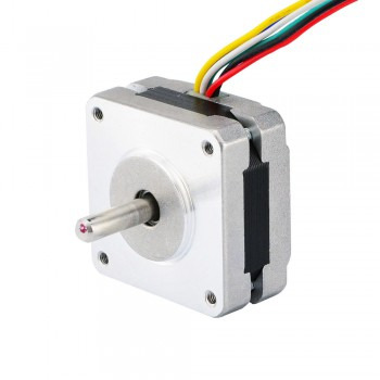
What are the design requirements for linear stepper motors?
1.Basic principle of linear stepper motors The basic principle of linear stepper motors is to convert rotational motion into linear motion. The linear stepper motor contains a magnetic rotor core inside, which interacts with the pulsed electromagnetic field generated by the stator to generate rotation. Specifically, the linear stepper motor usually adopts a screw and a nut meshing method, and prevents the screw and the nut from rotating relative to each other in some way, so that the screw moves axially.

2.Basic structure of linear stepper motors The basic structure of linear stepper motors includes main parts such as stator assembly, rotor assembly, front cover, rear cover, and screw assembly. Specifically, there are multiple first teeth and first tooth slots on the inner circumference of the stator assembly, and multiple second teeth and second tooth slots on the outer circumference of the rotor assembly. A part of the second tooth corresponds to the first tooth, and a magnetic strip is installed in the first tooth slot, and another part of the second tooth corresponds to the magnetic strip.
3.Durability of linear stepper motors
1.Service life: The service life of a linear stepper motor mainly depends on its use environment and the loss of mechanical parts. The motor itself has no brushes to wear, so its lifespan usually exceeds that of other mechanical parts in the system. The main factors affecting lifespan include workload, working environment, bearing quality, etc. For example, running the motor at or near maximum thrust will significantly affect its lifespan, while maintaining a thrust margin of more than 50% can extend the motor life. 2. Working environment: The working environment has a significant impact on the lifespan of the linear stepper motor. High humidity, chemicals, dirt, and heat will accelerate the loss of motor parts, thereby shortening the motor life. In addition, mechanical factors such as side loads on the shaft, unbalanced loads, and eccentricity during installation will also have an adverse effect on the motor life. 3. Care and maintenance���: Regular care and maintenance can significantly extend the service life of the linear stepper motor. Maintenance measures include keeping the motor clean and avoiding oil, dust, and water pollution; regularly checking the wear of the bearings and replacing them in time; ensuring that the motor operates in a suitable environment to avoid high temperature and humidity; and reasonably controlling the supply voltage and current to avoid overload operation. 4. Design features: Linear motors have the advantages of high efficiency, high speed and compact design. Due to its contactless force transmission characteristics, the mechanical friction loss is almost zero, so there are few faults, maintenance-free, safe and reliable operation and long life.

4.Design requirements for linear stepper motors 1. Load capacity: The static and dynamic loads of the system need to be considered during design. Static load refers to the maximum thrust that the motor can withstand when it is stationary, while dynamic load refers to the maximum thrust that the motor can withstand when it is moving. These two loads together determine the basic size and performance of the motor. 2. Operating speed: The operating speed of a linear motor is closely related to the lead of the screw. Engineers need to carefully select the appropriate lead of the screw according to the speed required by the system. Generally speaking, it is recommended to use a screw with a smaller lead when the speed is low, and a screw with a larger lead should be selected for optimal performance when the speed is high. 3. Accuracy requirements: The accuracy requirements of the system include linear accuracy and repeatability. Linear accuracy refers to the error between the actual stroke and the theoretical stroke after the lead screw rotates multiple times, while repeatability refers to the accuracy with which the system can repeatedly reach the specified position. These indicators are critical to the performance of the system. 4. Backlash: Backlash is the relative axial movable amount of the lead screw and nut when they are stationary. As the working time increases, the backlash may increase, so special attention needs to be paid to backlash compensation or correction, especially in applications that require bidirectional positioning. 5. Installation and connection: When designing, it is also necessary to consider whether the installation method of the linear stepper motor meets the mechanical design requirements, how to connect the moving object to the nut, and the effective stroke of the lead screw and the matching driver. 6. Material selection: In the design process, the selection of materials is also very important. For example, the selection of parameters such as the magnetic flux density of the core, the current density of the coil, and the slot fill rate will affect the performance and efficiency of the motor. Too high a magnetic flux density will lead to increased iron loss, while too high a current density will increase the resistance and temperature rise of the coil. 7. Structural type: There are three main structural types of linear stepper motors: external drive type, through-shaft type and fixed-shaft type. Each structural type has its specific application scenarios and design requirements.
0 notes
Text
How to control the CNC spindle motor?
1.Definition of CNC spindle motor A CNC spindle motor is a critical component in a CNC machine, the main function of the spindle motor is to drive the spindle of the mechanical equipment to rotate, so as to complete tasks such as processing and cutting. Its performance directly affects the processing accuracy, efficiency and stability of the equipment.

2.Working principle of CNC spindle motor The operation of the CNC spindle motor is based on the principle of electromagnetic induction. When AC is applied to the three-phase winding, a rotating magnetic field is generated in the stator. This rotating magnetic field cuts the rotor conductor, thereby generating an induced current in the rotor conductor. The induced current interacts with the rotating magnetic field to generate an electromagnetic force that drives the rotor to rotate. There is a certain difference between the speed of the rotor and the speed of the rotating magnetic field. This difference is called the slip. By controlling the slip, the spindle motor speed can be precisely controlled.
3.Components of CNC spindle motor
Stator:The stator is the stationary part of the motor and houses the windings. It is responsible for generating the magnetic field that interacts with the rotor.
Rotor:The rotor is the rotating part of the spindle motor. It is driven by the magnetic field created by the stator. The rotor is connected to the spindle shaft, which directly drives the cutting tool.
Bearings:Bearings support the spindle and allow it to rotate with minimal friction. High-quality bearings are crucial to ensure that the spindle motor operates smoothly and accurately, as they help to reduce vibrations and ensure precision during operation.
Spindle Shaft:The spindle shaft is the central part that connects the rotor to the tool being used in the machining process.
Cooling System:Cooling systems are vital to keep the spindle motor temperature within safe operating limits, especially during high-speed operation.
Encoder:The encoder provides feedback on the position and speed of the spindle motor. It allows the CNC system to accurately control the motor's speed and positioning by sending signals about the rotor's movement to the machine's control system.
Drive System:The drive system consists of components that convert electrical energy into mechanical energy to rotate the spindle. It includes components like the motor controller, inverter, and drive circuitry.
VFD (Variable Frequency Drive):The VFD is used to control the motor's speed by adjusting the frequency of the electrical supply.
Cooling Fan:A cooling fan (or ventilation system) is sometimes incorporated into the motor assembly to provide active air cooling.
Housing:The housing is the outer casing of the spindle motor that protects the internal components, such as the stator, rotor, and bearings, from dirt, debris, and damage.
Electrical Connections:These are the wiring and connectors that supply power to the motor and interface with the CNC controller and other components.
Feedback System:Some advanced spindle motors include additional feedback systems, such as tachometers or resolvers, which provide more precise information on motor speed and position.

4.The control modes of CNC spindle motor
Constant Speed Control Mode:In this mode, the spindle motor runs at a fixed, constant speed throughout the machining process.It is used for operations where the tool does not need to change its speed dynamically during the process.
Constant Torque Control Mode:This mode adjusts the motor’s speed to maintain a constant torque throughout the operation, ensuring the motor delivers consistent cutting force.This is ideal for machining operations where the cutting load varies but the motor's torque needs to remain steady to prevent tool stalling.
Vector Control (Field-Oriented Control, FOC) Mode:Vector control provides high precision and dynamic control of the motor by controlling the magnetic field inside the motor. It adjusts both the torque and speed based on real-time demands.This mode is particularly useful in high-performance CNC systems, providing smoother operation, better acceleration/deceleration, and high-speed control.
Closed-Loop Control Mode:Closed-loop control involves a feedback system where the motor speed, torque, and position are continuously monitored, and adjustments are made in real-time to keep the system running optimally.Feedback devices like encoders or resolvers help achieve high precision and accuracy by adjusting motor parameters to ensure the desired output is achieved.
Open-Loop Control Mode:In open-loop control, there is no feedback mechanism to adjust the motor’s operation based on real-time performance.The motor is controlled based on pre-set parameters, such as speed or power, without ongoing monitoring or adjustments.
Synchronous Motor Control:Synchronous motors operate at a fixed speed, determined by the frequency of the electrical supply.These motors are typically used when precise speed control is required, as they run at a constant speed without fluctuating under load.
Dynamic Brake Control Mode:Dynamic braking is often used for rapid deceleration of the spindle motor after the machining process is completed.This method uses the motor itself to dissipate the kinetic energy, slowing down the motor quickly by converting it into heat.
Speed and Torque Control Mode (Dual Mode):This control mode combines both speed and torque control to give the spindle motor the ability to adjust both parameters simultaneously.
0 notes
Text
What are the Reasons why Diesel Generators do not Generate Electricity
Diesel three-phase generator usually refers to the electromagnetic device driven by the prime mover to generate current, leading to three fire wires so as to achieve a higher voltage power. If you encounter a failure can not work properly, it is likely because the generator line or magnetic circuit is damaged, today Dingbo Power will introduce you about what are the reasons why the diesel three-phase generator sets do not generate electricity .
1. Diesel three-phase generator does not run according to the limited technical conditions, such as high stator voltage, load current is too large, stator winding copper loss increases.
2. The frequency is too low, so that the cooling fan speed slows down, affecting the generator heat dissipation, the power factor is too low, so that the rotor excitation current increases, affecting the rotor heat.
3. It is necessary to check whether the indication of the monitoring instrument is normal. If it is not normal, necessary adjustments and treatments should be implemented to ensure that the generator operates according to the required technical conditions.
4. If the diesel three-phase engine does not generate power, it may also be that the three-phase load current of the generator is unbalanced, and the overload of the single-phase winding will overheat. If the three-phase current difference exceeds 10% of the rated current, it is a serious imbalance of the direct current, and the imbalance of the three-phase current will cause negative sequence magnetic field, then it will add losses, which will affect the heating of components such as magnetic pole winding and iron ring. The three-phase load should be adjusted to make the phase current maintain balance as much as possible.

5. Insufficient cooling water or cooling water, oil temperature is too high in the case of operation. Insufficient diesel generator cooling water will reduce its cooling effect, the diesel engine because of the lack of effective cooling and overheating. Cooling water, oil temperature is too high, will also cause diesel engine overheating. At this time, the diesel generator cylinder head, cylinder liner, piston assembly and valve, etc. are mainly subjected to heat load, its mechanical properties such as strength, toughness and other sharp decline, so that the deformation of the parts increased, reducing the fit clearance between the parts, resulting in the inability to generate electricity.
6. Stop the machine immediately after sudden unloading or emergency shutdown with load. After the diesel engine generator is turned off, the circulation of cooling water in the cooling system stops, and the heat dissipation capacity sharply decreases. The heated parts lose cooling, which can easily cause overheating of cylinder heads, cylinder liners, cylinder blocks, and other components, resulting in cracks or excessive expansion of the piston and jamming in the cylinder liner. On the other hand, if the diesel generator is shut down without cooling at idle speed, the friction surface will be lack of oil. When the diesel engine is restarted, the wear will be aggravated due to poor lubrication. Therefore, before the diesel generator flameout, the load shall be removed, and the speed shall be gradually reduced, and the no-load operation shall be carried out for a few minutes, otherwise it will be easy to fail to generate electricity.
7. Brush and slip ring fault: if the brush and slip ring are in poor contact or the spring pressure is too small, this situation will also cause the diesel generator to fail to conduct normal flow, thus generating no power.
We hope the above information will be helpful to you. Dingbo Power is a professional and experienced manufacturer of diesel generator sets. If you are looking for diesel generator sets or you are interested in diesel generator sets, please contact us by email [email protected] .
0 notes
Text
LG AJB73816015 Washing Machine Stator Assembly HnKParts

The LG AJB73816015 Washing Machine Stator Assembly is a vital component that helps to drive the motor of your washing machine. It is designed to generate the necessary magnetic field to rotate the drum and agitate the laundry. Made of high-quality materials, this stator assembly ensures durability and efficient performance.
If you're looking for a reliable replacement, the LGE Washing Machine Stator Assembly is an excellent choice for the smooth operation of your home appliance.
0 notes
Text
How to drive a unipolar stepper motor
1.Introduction A unipolar stepper motor is a special stepper motor, which is characterized by achieving stepping motion through a specific driving mode. This motor usually has a permanent magnet with 5 or 6 wires and a hybrid structure. Its working principle is based on a design in which each of the two windings has a central tap. In use, the center tap of the winding is usually connected to the positive power supply, and the two ends of each winding are alternately grounded to reverse the direction of the field provided by the winding.

2.Working mode of unipolar stepper motor 1.In the single-phase driving mode, the stepper motor has only one set of windings, which is connected to an external power supply to make the magnetic field on the stator change continuously within a cycle. When the magnetic field changes, the rotor rotates with the change of the magnetic field. The advantages of this method are simple structure, easy control and implementation, but it is easy to lose step when running at low speed. 2.The two-phase drive method is different. It involves two sets of windings in the stepper motor. The windings are connected to an external power supply to make the magnetic field on the stator change alternately. Only one set of windings is energized at a time, attracting or repelling the rotor, causing the rotor to rotate clockwise or counterclockwise. Compared with the single-phase drive method, the two-phase drive method has better performance and stability, but the implementation is relatively complicated.
3.The drive method of unipolar stepper motor 1.The drive method of unipolar stepper motor mainly involves unipolar drive circuits. This drive method uses four transistors to drive the two phases of the stepper motor. The structure of the motor includes two sets of coils with center taps, and the entire motor has a total of six wires connected to the outside world. This motor is sometimes called a four-phase motor, but in fact it has only two phases, and a more accurate description should be a two-phase six-wire stepper motor. The characteristic of the unipolar drive circuit is that the current in the motor coil has only one direction, the current direction does not change. This characteristic makes the unipolar motor relatively simple to drive. 2.The driving methods of unipolar stepper motors also include the three most basic methods: single 4-beat method, double 4-beat method and single double 8-beat method. In the single 4-beat driving process, only one phase is energized at each moment, while the double 4-beat method is that two adjacent phases are energized at each moment. These two methods have their own characteristics. The former only works in one phase at a time, and the latter provides a greater output torque by driving two adjacent phases at the same time. The single double 8-beat method is a hybrid driving method that combines the single 4-beat method and the double 4-beat method. It completes a cycle through 8 steps. This method is more suitable for occasions where a greater output torque is required. In addition, the driving circuit of the two-phase unipolar stepper motor is basically the same as the driving circuit of the two-phase bipolar stepper motor in terms of input segment configuration, internal logic, control circuit and drive circuit use, but the output segment configuration is different. Two-phase bipolar stepper motors are driven using a dual-channel H-bridge, while two-phase unipolar stepper motors are driven using two switches (MOSFET) in two channels. This is because a two-phase unipolar stepper motor can be driven by making the current flow in a certain direction from the power supply supplied to the center tap of each coil.
4.Application areas of unipolar stepper motors 1.Robot control: Unipolar stepper motors are suitable for robot control operations, such as in manufacturing and assembly line control. By accurately controlling the rotation angle and step length of the stepper motor, the robot can achieve precise motion and position control to complete various tasks. 2.Medical equipment: Unipolar stepper motors are also suitable for medical equipment, such as synchronous or high-speed motion control. In medical equipment, stepper motors are used to control the movement and position of medical devices, for example, to control the rotation angle and position of X-ray equipment, and to control the joint drive system of surgical robots. 3.Automation equipment: unipolar stepper motors are suitable for automated production processes, such as fast and precise position control on conveyor belt systems, and robots that inspect and assemble parts in automobile manufacturing. 4.Joint drive systems and positioning systems in robotics: stepper motors are widely used in joint drive systems and positioning systems in robotics. By controlling the rotation angle and step length of stepper motors, precise motion and position control can be achieved to complete various tasks.
Source:https://olgana.pixnet.net/blog/post/176250202
0 notes
Text
Động cơ công nghiệp nổi tiếng trên thế giới
Industrial motors are an indispensable device in the electromechanical systems of many industries. This device plays an important role in providing energy to control machinery and equipment to help the production process run continuously and efficiently. Join Tesfa to see more clearly about industrial motors and the presence of some famous manufacturers in the world through the following article.
What is an industrial engine?
An industrial motor is a type of mechanical device used to convert electrical energy or mechanical energy into mechanical movement. With a special design to operate durably and effectively in harsh industrial environments, requiring high performance. In industrial environments, they are often used in machinery such as compressors, pumps, fans and other mechanical equipment.
Motors are widely used in many different fields such as: production and processing, automation systems, water and waste treatment, mining industry...

Structure of industrial engines
Industrial engines are usually composed of the following main components:
Stator (fixed coil): Is a non-moving part that contains magnetic coils and is responsible for creating a magnetic field when current flows through it.
Rotor (Rotating coil): Is the moving part of the motor, rotating inside the stator under the influence of a magnetic field. Rotors are often made from thin steel sheets assembled to reduce magnetic loss.
Windings: Windings in the stator and rotor help create the magnetic field needed for the motor to operate.
Commutator: Is a switching part that helps change the direction of current in the rotor's coil, adjusting the magnetic field so that the rotor rotates continuously.
Motor Shaft: The shaft is the connection between the rotor and peripheral mechanical devices. It transmits power from the motor to other devices through transmission mechanisms such as gears, belts or screws.
Bearings: Supports the rotor to rotate smoothly and reduces friction in the engine.
Motor Housing: Protects internal motor components and provides mechanical connection to other systems.

Classification of industrial engines
Industrial engines can be classified based on many different criteria, including:
Based on energy source
Electric motor: Uses electricity to create mechanical movement.
Diesel engine: Uses diesel fuel, popular in heavy applications and harsh environments.
Pneumatic motor: Uses compressed air to create motor force.

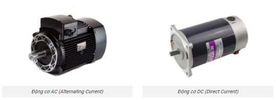
Based on structure
AC (Alternating Current) motor: Operates with alternating current, common in common industrial applications.
DC (Direct Current) Motor: Operates with direct current, providing easy speed adjustment.
Based on the type of movement
Induction motor: No need for brushes or commutator, suitable for many industrial applications.
Synchronous motor: Ensures the correct rotation speed with the power source frequency.

The role of engines in industry
From light to heavy industries, engines now play a key role in equipment and machinery. Let's take a look at some of the roles below:
Providing motion: Industrial electric motors create the mechanical motion needed to operate machinery and equipment in factories.
Enhanced production efficiency: By providing driving force to automated systems, motors help increase production efficiency and productivity.
Control processes: Motors can adjust speed and direction of motion to control production processes more precisely.
Ensures Stability: Industrial motors help maintain stability in system operations, minimizing disruptions and enhancing reliability.
Famous industrial engine manufacturers
Grundfos: Is one of the world's leading manufacturers of industrial motors and pumping equipment, distinguished by providing effective and durable solutions for many industrial fields. Founded in Denmark in 1945, Grundfos has built a solid reputation thanks to excellent product quality and innovative technology. Grundfos provides a wide range of industrial motors, notably products such as Pump motors, control motors, AC and DC motors...
SEW-EURODRIVE: Or commonly known simply as SEW, is one of the leading manufacturers of industrial motors and drive systems. SEW specializes in providing industrial motor products including asynchronous motors, synchronous motors, servo motors and similar motors. These are important products in drive systems and automation in many industries.
ABB (Asea Brown Boveri): Is one of the leading technology corporations that stands out for providing solutions in the fields of electricity, automation and industrial drives. ABB has built a strong reputation thanks to product quality and technological innovation. Providing a wide range of electric motors, from standard motors to special motors for complex industrial applications including: high efficiency motors, explosion-proof motors, Servo motors, synchronous motors and asynchronous,…
TESFA COMPANY LIMITED is currently a reliable strategic partner chosen by Grundfos, Sew and ABB to represent and distribute their industrial engine products in the Vietnamese market. Please contact us now to receive support and experience quality products.
1 note
·
View note
Text
Yoyik offer valve SL20PB3-L4X for power station
"Yoyik offer valve SL20PB3-L4X for power station Main: hydraulic machinery and components, hydroelectric generating units; coal-fired generating units; generating units; electrical and electronic products processing; mechanical parts processing. Mainly engaged in the power industry host (steam turbine, water machine, boiler, turbine) accessories, spare parts, spare parts, auxiliary equipment and environmental protection equipment. Deyang YOYIK supply power plant, steel accessories are as follows:
Yoyik can offer many spare parts for power plants as below:
DF-valve SL20PB3-L4X-DF
relief valve RPGC1AV ac vacuum pump M02225 0BMCCI 1.5A vertical centrifugal pump YNKN300/200-20Y/J magnetic coupling centrifugal pump DFB80-50-20 piston hydraulic pump A3H56-FR01KK-10-X33 vacuum pump rotary vane F3-V10-IS6S-IC-20 reciprocating piston pump PVH74QIC-RSF-1S-10-C25 mechanical seal 43 mm AZ40-160B vane vacuum pump F320V12A1C22R electric oil pump 80AYZ-70 BFP cv actuator HTGY6E.0 oil pump HS76685,10BARG piston pump F3-V10-1S6S-1C20 vaccum pump 125LY-40-B mechanical seal 8b1d axial piston pumps PVH098R01A250000002001AB010A pressure hose SMS-12/15-305mm-B central lubrication pump 2CY-403/2.5 high pressure centrifugal pump CZ50-250C reciprocating piston pump PV29 2RID CO2 sealing ring HB4-56J8-37 Screw in connector Q/D9111G-77(87) Dg32 vacuum pump 259v P-1916 screw pump diagram HSNH280-54A oil seal TCM589332-OOG pressure hose SMS-12/N1/4-3048mm-C piston pump parts PVH131Q1C.RSF.10.C25 pressure hose SMS-12/15-3048mm-B solenoid valve RV5-10-0-35 hydraulic piston pump spare parts 70LY-34*2 Gear oil pump CB-1.2 vacuum pumps P-1931A industrial vacuum pump P-1753 electric centrifugal pump head IHF80-50-200 Check valve FPR12 0.5 AST/OPC solenoid valve coil CCS230D 16.5W 230VAC valve SL20PB3-L4X
repair coupling 125LY-31-6 stainless steel Throttle valve (flange) 50BJ-1.6P with reverse flange electric pump for lubrication 2CY45/9-1 sealing ring HB4-56J8-62 ac vacuum pump P-1433 accumulator oil-feeding globe valve DN25 dc screw pump NM063BT01L06V vacuum pump oil PVH74QIPRM-IS dc centrifugal pump IS80-50-200 piston pump parts PV29-2R5D-C00 Bearing Bush 88/100(130 mechanical face seal G50 vacuum pump price P-1825B Charging and pressure measuring assembly of EH oil accumulator NXQ-AB-40/20-L-A Fast exhaust valve XQ171000 makeup water solenoid valve K25FJ-1.6PA2 pumps centrifugal KQW100/200-22/2 Angle joint C-EW-L06-SS water pump SDH200-150-315 Recirculating oil pump mechanical seal DLXB850-R67 Proportional Relief valve E-RI-TERS-PS-01H/I 20 stator water pump 125-80-260 screw pump diagram 3GR30*4H2 Guide bearing B 9LDTNA-4-006 vacuum pump KZ/100WS solenoid valve GS061600V pump vacuum ZS-185A hydraulic pump spare parts 50SDZLJ-50 solenoid valve DSG-03-3C2-A240-N1 vacum pump air vacuum P-1964-1 actuator 1320B-333000A industrial centrifugal pump DFB125-125-250 dc centrifugal pump SDH200-150-315 piston hydraulic pump A10VS071DRS/32R-VPB22U99 electric motor centrifugal water pump DFB-100-80-230 multi stage centrifugal pump KQW100/200-22/2 valve SL20PB3-L4X
DFYLSYC-2024-7-8-A
"
0 notes
Text
Understanding Aircraft Alternator Parts: Essential Components and Their Functions
Aircraft alternators are crucial components in an aircraft's electrical system, providing a reliable source of electrical power to support various systems and instruments. Understanding the parts of an aircraft alternator and their functions can help ensure the maintenance and efficiency of the aircraft. In this article, we'll delve into the essential parts of aircraft alternators and their roles.
1. Rotor
The rotor is a central component of an aircraft alternator, responsible for generating a magnetic field. It consists of a shaft and winding, which rotates within the stator to produce electricity. The rotor is typically driven by the aircraft's engine, converting mechanical energy into electrical energy through electromagnetic induction.
2. Stator
The stator is a stationary part of the alternator that surrounds the rotor. It contains coils of wire, known as windings, where the induced current is generated as the rotor spins. The interaction between the rotor's magnetic field and the stator windings produces alternating current (AC).
3. Rectifier Assembly
Since most aircraft systems require direct current (DC), the rectifier assembly converts the AC produced by the alternator into DC. This assembly consists of diodes, which allow current to flow in only one direction, effectively transforming the alternating current into a usable direct current for the aircraft's electrical systems.
4. Brushes and Slip Rings
Brushes and slip rings work together to provide a continuous electrical connection between the rotating rotor and the stationary external circuit. The slip rings are mounted on the rotor shaft, while the brushes are fixed and make contact with the slip rings. This setup ensures a stable transfer of electrical power from the rotor to the aircraft's electrical system.
5. Voltage Regulator
The voltage regulator is a critical component that maintains a constant output voltage from the alternator, regardless of engine speed or electrical load variations. It adjusts the current flowing to the rotor winding, controlling the strength of the magnetic field and, consequently, the alternator's output voltage. A stable voltage is essential for the proper functioning of sensitive electronic equipment onboard.
6. Bearing Assembly
The bearing assembly supports the rotor shaft, allowing it to spin smoothly within the stator. These bearings must withstand high rotational speeds and temperature variations, ensuring the rotor's stable and efficient operation over time.
7. Cooling System
To prevent overheating, aircraft alternators are equipped with a cooling system. This typically involves a fan or air vents that dissipate heat generated during operation. Efficient cooling is vital to maintain the alternator's performance and longevity.
8. Drive Mechanism
The drive mechanism connects the alternator to the aircraft engine, transmitting mechanical power to the rotor. This can be achieved through belts, gears, or direct coupling, depending on the aircraft's design. The drive mechanism must be robust and reliable to ensure the continuous operation of the alternator.
Importance of Regular Maintenance
Regular maintenance of aircraft alternators and their parts is essential to ensure optimal performance and prevent electrical failures. Maintenance tasks include inspecting and replacing worn brushes, checking bearings for wear, ensuring proper cooling, and verifying the functionality of the voltage regulator. By adhering to a strict maintenance schedule, aircraft operators can enhance the reliability and safety of their electrical systems.
1 note
·
View note
Text
The Intricacies of Power Screwdrivers and Brushed Motors
The Intricacies of Power Screwdrivers and Brushed Motors
In the realm of power tools, power screwdrivers hold a significant place. These tools, powered by brushed motors, have revolutionized the construction and manufacturing industries. This essay delves into the intricacies of power screwdrivers and their brushed motors, exploring their operation, advantages, and applications.Get more news about power screwdrivers brushed motor,you can vist our website!
Power screwdrivers, as the name suggests, are electric tools designed to drive screws. They are a staple in any toolbox, be it for a professional contractor or a do-it-yourself enthusiast. The primary component that powers these tools is the brushed motor.
Brushed motors are the heart of many power tools, including power screwdrivers. They consist of four basic parts: the stator, rotor (or armature), brushes, and a commutator. The stator generates a static magnetic field, and the armature contains windings that, when energized, create a second magnetic field. The interaction between these two fields causes the armature to rotate, providing the necessary torque to drive a screw.
One of the main advantages of brushed motors is their simplicity and reliability. They are easy to control and maintain, making them ideal for power tools like screwdrivers. Moreover, they provide excellent torque at low speeds, which is crucial for driving screws accurately and efficiently.
However, brushed motors are not without their drawbacks. The brushes create friction, leading to wear and tear over time. This friction also generates heat, which can reduce the motor's efficiency and lifespan. Despite these challenges, brushed motors' benefits often outweigh their disadvantages, especially in applications like power screwdrivers.
Power screwdrivers with brushed motors find extensive use in various sectors. In construction, they are indispensable for tasks like building furniture or installing drywall. In manufacturing, assembly lines often use power screwdrivers for fast and efficient production. Even in home settings, these tools prove invaluable for minor repairs and DIY projects.
In conclusion, power screwdrivers and brushed motors share a symbiotic relationship. The brushed motor, with its simplicity and reliability, powers the screwdriver, enabling it to perform its function effectively. Despite some challenges, this combination has proven successful, making power screwdrivers an essential tool in various industries. As technology advances, it will be interesting to see how these tools evolve, but for now, power screwdrivers with brushed motors continue to hold their ground in the power tool landscape.
0 notes
Text
Cooling Systems for High-Performance Permanent Magnet Machines: Challenges and Innovations

In the realm of high-performance permanent magnet machines, effective cooling systems play a pivotal role in maintaining optimal operating temperatures, ensuring efficiency, and prolonging the life span of the machinery. Whether in electric vehicles, wind turbines, industrial machinery, or other applications, the demand for powerful permanent magnet machines has surged, necessitating innovative cooling solutions to tackle thermal challenges.
The Challenges:
One of the primary challenges faced by high-performance permanent magnet machines is managing heat dissipation. The continuous operation of these machines leads to the generation of significant heat levels, which, if not efficiently managed, can impair performance and reliability. Excessive heat can degrade the magnetic properties of the permanent magnets, leading to a decline in efficiency and potentially causing irreversible damage to the machine.
Moreover, the compact nature of these machines, aimed at maximizing power-to-weight ratios, often restricts the available space for incorporating conventional cooling systems. Traditional cooling methods like air cooling or liquid cooling may not suffice to adequately address the thermal dissipation requirements without compromising the machine's design or performance.
Innovations in Cooling Systems:
To counter these challenges, engineers and researchers have been exploring and developing innovative cooling techniques tailored to the specific needs of high-performance permanent magnet machines.
Liquid cooling systems have emerged as a prominent solution, leveraging the higher heat transfer capabilities of liquids compared to air. By circulating coolants through channels or jackets within the machine, heat dissipation can be more efficiently managed. Advanced designs utilizing micro-channel cooling or direct impingement cooling offer improved thermal performance while minimizing the system's footprint.
Furthermore, the use of phase change materials (PCMs) has gained attention for thermal management in permanent magnet machines. These materials absorb and release thermal energy during phase transitions, effectively regulating temperatures within the machinery. Integrating PCMs into the machine's structure or as part of the cooling system can help in stabilizing temperatures and mitigating thermal fluctuations.
Enhanced materials and coatings have also contributed to improving cooling efficiency. Manufacturers are exploring advanced materials with better thermal conductivity to dissipate heat more effectively from critical components such as stator windings and rotor assemblies. Additionally, coatings that enhance heat transfer and protect against corrosion are being developed to prolong the lifespan of the machine.
Innovative designs integrating computational fluid dynamics (CFD) simulations and advanced modeling techniques enable engineers to optimize cooling system layouts. This approach allows for the creation of intricate internal structures and channels that enhance the flow of coolants while minimizing pressure drops, ensuring efficient heat transfer across the system.
Furthermore, smart monitoring and control systems equipped with sensors and predictive algorithms have been introduced to continuously monitor temperatures and performance parameters. These systems enable proactive maintenance, allowing for timely interventions to prevent overheating or performance degradation.
In conclusion, the development of high-performance permanent magnet machines requires a holistic approach that addresses the formidable challenges posed by thermal management. Innovations in cooling systems, including liquid cooling technologies, phase change materials, advanced materials, computational modeling, and smart monitoring, signify the ongoing efforts to enhance efficiency, reliability, and longevity of these machines. As demand grows for more powerful and compact permanent magnet machines in various industries, continuous advancements in cooling systems will be fundamental in unlocking their full potential while ensuring sustainability and reliability in operation.
0 notes
Text
Control method and application of permanent magnet stepper motor
1.Working principle of permanent magnet stepper motor The working principle of permanent magnet stepper motor is based on magnetic field interaction and electromagnetic induction. When currents of different phases are applied to the stator winding, a rotating magnetic field is generated. This rotating magnetic field interacts with the permanent magnets on the rotor, causing the rotor to be attracted from one pole pair to another in sequence, thereby realizing rotational motion. By changing the power-on state, the rotation direction and step angle of the motor can be controlled.

2.Structural characteristics of permanent magnet stepper motor 1.Design of rotor and stator: The rotor of a permanent magnet stepper motor is composed of permanent magnets, while the stator usually contains electromagnetic coils or windings. The permanent magnets on the rotor are usually magnetized radially with multiple poles, while the pole pieces on the circumference of the stator inner hole are arranged in a claw-shaped annular symmetry. 2.Magnetic isolation sheet and annular winding: The stator and rotor of the entire motor are axially divided into two sections, separated by a magnetic isolation sheet in the middle, and the two sections are separated by a step angle. There are annular windings on each stator section, and these windings are usually connected in reverse series. 3.Cost and efficiency: The cost of permanent magnet stepper motors is relatively low, and the control power is small and the efficiency is high. Since the rotor is a permanent magnet, there is torque holding force when there is no excitation, which allows the motor to maintain a certain torque even in the non-excitation state. 4.Step angle and step angle: The step angle of permanent magnet stepper motors is large, and common step angles include 5.625°, 7.5°, 11.25° and 15°.
3.Control method of permanent magnet stepper motors 1.Control (FOC): Vector control is one of the most widely used permanent magnet synchronous motor control strategies. It is based on the mathematical model of the motor and space vector modulation technology, and achieves precise control of the motor by controlling the rotor magnetic field and stator current of the motor. 2.Direct torque control (DTC): DTC uses Bang-Bang control (hysteresis control) to generate PWM signals to optimally control the switching state of the inverter, thereby obtaining torque control with high dynamic performance. Its basic operation is to transmit the error between the set value and the actual value of the flux torque to the hysteresis comparator, and obtain the appropriate motor space vector through the offline operation switch table to realize the speed control of the motor. 3.Magnetic control: The purpose of weak magnetic control is to increase the speed of the DC motor. By reducing the excitation current of the motor and reducing the excitation flux, the motor speed can be increased to above the rated speed under the condition of ensuring voltage balance. For permanent magnet synchronous motors, weak magnetic control weakens the air gap flux by increasing the demagnetization component of the stator current, thereby achieving the purpose of increasing the motor running speed.
4.Common applications of permanent magnet stepper motors 1.In the field of industrial automation, permanent magnet stepper motors are often used to drive various mechanical equipment to achieve precise control of production lines. For example, in automated assembly lines, automated packaging lines, and automated conveyor lines, permanent magnet stepper motors can drive conveyor belts, elevators, rotary tables and other equipment to improve production efficiency and accuracy. 2.In the field of robotics, permanent magnet stepper motors are widely used in industrial robots, service robots, drones and other equipment. Due to its high efficiency, high response speed and high torque density, permanent magnet stepper motors can provide powerful power support for robots and achieve high-precision and high-speed motion control. 3.In the field of textile machinery, permanent magnet stepper motors can be used in textile machines, looms and dyeing and finishing equipment. It can replace traditional AC motors, achieve precise control of textile machinery, and improve production efficiency and product quality. 4.In the field of printing machinery, permanent magnet stepper motors are used in equipment such as printing machines, paper cutters and folding machines. It can achieve precise control of printing machinery and improve printing speed and printing quality. Household appliances and agricultural machinery 5.In the field of household appliances, permanent magnet stepper motors gradually replace traditional AC asynchronous motors and are used in equipment such as air conditioners, washing machines, refrigerators and televisions. 6.In the field of agriculture, permanent magnet stepper motors are also widely used in agricultural machinery and irrigation equipment to improve the efficiency and reliability of equipment.
0 notes
Text
The main functions and common applications of servo motors
1.A brief introduction to servo motors A servo motor is an engine that controls the operation of mechanical elements in a servo system. It is an auxiliary motor indirect speed change device. A servo motor can convert voltage signals into torque and speed to drive the control object. Its core features are very high control speed and position accuracy. It can be used as an actuator in an automatic control system and has characteristics such as small electromechanical time constant and high linearity.

2. Structural components of servo motors 1. Stator: Made of laminated silicon steel sheets, with three-phase windings embedded to form a rotating magnetic field. The stator is the fixed part of the motor, usually called the excitation winding of the motor. 2. Rotor: Made of permanent magnetic material, it rotates with the rotating magnetic field. The rotor is the rotating part of the motor, usually called the armature winding. 3. Encoder: Used to detect the position and speed of the rotor, usually installed on the rotor shaft. The encoder has an approximate sensor that can determine the speed and revolutions per minute of the motor. 4. Driver: Receives instructions from the controller and converts them into drive signals to control the operation of the servo motor. The driver controls the speed and direction of the rotating magnetic field by controlling the current of the three-phase coil, thereby controlling the speed and direction of the servo motor.
3.The main functions of the servo motor 1. Accurately control the speed and position: The servo motor can accurately control the speed and position according to the change of the voltage signal to achieve uniform and stable movement. It is positioned by pulse signals. Every time a pulse current is received, it will rotate a corresponding angle, thereby achieving high-precision positioning with an accuracy of up to 0.001mm. 2. Convert voltage signals into torque and speed: The servo motor can convert the input voltage signal into torque and speed to drive the control object. This feature makes it an important actuator in the automation control system. 3. Fast response and high-precision feedback: The servo motor has the characteristics of fast response and can respond to the input signal in a short time. At the same time, it uses a closed-loop control system to feedback pulse signals in real time to ensure the accuracy of motion control. 4. Suitable for high-precision positioning scenarios: Servo motors are widely used in scenarios that require precise positioning, such as CNC machine tools, steering gears, etc. Its fast start-stop speed, small rotational inertia, large starting torque and rapid braking make it perform well in these fields. 5. Core role in servo system: The servo motor is a key component in the servo system, used to control the operation of mechanical elements. It achieves high-precision motion control by converting electrical signals into angular displacement or angular velocity output.

4.Common application industries of servo motors 1. Industrial automation: Servo motors are commonly used in CNC machine tools, printing equipment, packaging machinery and food processing equipment, etc., which can achieve high-precision and high-speed motion control and significantly improve production efficiency and product quality. In automated production lines, servo motors are used in robotic arms, conveyor belts, assembly machines, etc. to achieve precise position and speed control. 2. Robotics: Servo motors are key components of robot joint drives, which can convert electrical energy into mechanical energy, enabling robots to perform precise movements according to predetermined paths and motion modes. 3. Aerospace: Servo motors are used for attitude control and rudder drive of aircraft to ensure stable flight of aircraft in various environments. 4. Automotive manufacturing: Servo motors are used in engine management, brake systems, steering systems, etc. in automotive manufacturing to improve the performance and safety of automobiles. 5. Medical equipment: Servo motors are widely used in surgical robots, X-ray machines, CT scanners and other equipment to improve the accuracy and safety of medical operations. 6. Research equipment: Servo motors are used in scientific research for precision measurement, data analysis and other equipment to improve the accuracy and reliability of experiments. 7. Other industries: Servo motors are also used in medical examination equipment such as CT machines, B-ultrasound machines, and MRI machines to move patients; in the food packaging industry, such as the vacuum packaging production of snacks such as French fries; in the logistics and transportation industry, such as AGV vehicles in large storage warehouses for the transportation and allocation of goods; in microelectronics production and processing, such as chip production; and in cutting machines, such as water jet machines, which require servo motors to move the cutter head.
0 notes