#PIR Motion Sensor with Arduino
Explore tagged Tumblr posts
Visit Tumblr Blog
Explore Tumblr blogs with no restrictions, modern design and the best experience.
Last Seen Tumblr Blogs


Fun Fact
Users from the US are the majority of Tumblr visitors.
Text
youtube
Proximity sensing is a very common application in electronics. There are several ways to accomplish this. The most common way is by using a PIR sensor. PIR Sensor senses the change in ambient infrared radiation caused by warm bodies. I have already covered this in my Tutorial No. 5: "PIR Sensor Tutorial - With or Without Arduino". However, since PIR sensors detect movement from living objects, they can generate false alarms. These sensors are also inefficient in hot environments, as they rely on heat signatures.
The other common methods of proximity sensing involve, using reflected ultrasonic or light beams. Using these sensors, the intruding object is detected by the reflected beam back to its source. The time delay between transmission and reception is measured to calculate the distance to the object. In this tutorial, we are going to look at another method of proximity sensing using "Microwaves" and "Doppler Effect". In my hand is an inexpensive RCWL-0516 Microwave Radar Motion Sensor. The RCWL-0516 microwave sensor detects "any movement" from "any object" and does not rely on heat, making it more reliable in hot environments. I am going to use this sensor to create a Geo-fence around my house to detect motion and get notifications.
3 notes
·
View notes
Text
Building Enclosures
Title:
PIR Shield
Introduction:
For my midterm physical computing project, I used a PIR motion sensor to detect movement. The purpose of the sensor was to sense motion and trigger a response for a video game utilizing two sensors to complete the task. To protect the sensor and keep the wiring organized, I built a custom enclosure. Creating an enclosure was important not only for protecting the components from physical damage but also for improving the overall appearance and functionality of the project.
Enclosure Design:
I made the enclosure using blue acrylic in the innovation lab for visibility and sensor exposure. The enclosure includes specific openings for the PIR sensor itself, as well as for wires and USB cables connected to the Arduino. I chose this materials because they were easily available and easy to work with using basic tools, also because it held together with super glue/wood glue. The design ensures that the sensor is securely held in place while still allowing it to accurately detect motion.
Construction Process:
To build the enclosure, I first measured the size of the PIR sensor and the necessary space for wiring. I then cut out a prototype box shape from paper and carefully cut holes for the sensor, wires, and any ventilation if needed. After folding and assembling the box, I taped the edges to form a sturdy structure. After I assembled it, I used the measurements from the prototype to create clean cuts from the acrylic using the laser cutter. One of the challenges I faced was aligning the sensor opening perfectly so it would not block the sensor’s field of view. I overcame this by first testing the sensor placement on a temporary prototype, then transferring the measurements to the final enclosure. I mounted the PIR sensor inside the box by securing it near the front opening using hot glue and a support bracket made from extra cardboard. I made sure the sensor faced outward with no obstructions and enough clearance to detect motion effectively.


0 notes
Text
Arduino Projects
Arduino is a platform for open-source electronics that integrates software and hardware. Its integrated development environment (IDE) and programmable microcontroller board make coding and debugging easier. Its adaptability, affordability, and the vibrant developer community that constantly adds to its ecosystem are the main reasons for its appeal.
Beginner-Friendly Arduino Projects
The traditional "Hello World" of Arduino projects is LED blinking. By programming an LED to blink at various times, you may learn how to control it.
Temperature Monitor: Real-time temperature data are shown on a basic LCD screen using a temperature sensor.
Motion Detector: To build a simple motion-detection system, combine an Arduino board with a PIR sensor.
Components Commonly Used in Arduino Projects
Sensors include motion, light, gas, temperature, and humidity.
Actuators include relays, servos, and motors.
LED, LCD, and OLED displays.
Modules for communication: RFID, GSM, Bluetooth, and Wi-Fi.
Resources to Kickstart Your Arduino Journey
The official Arduino website offers thorough instructions and tutorials.
YouTube Channels: A wealth of detailed video lessons for all abilities.
Forums and Communities: Sites such as Reddit and Arduino.cc offer helpful assistance.
Online courses: Structured learning pathways are available on websites such as edX, Udemy, and Coursera.
Arduino projects are a prime example of ingenuity and originality, enabling people to realize their ideas. Arduino provides countless options for experimentation, learning, and development. regardless of your level of experience. For example, you can study the fundamentals or take on challenging tasks.
Explore the world of Arduino now to realize your creative potential and produce something truly remarkable. Your imagination is the only restriction!
To know more, click here.
0 notes
Text
Shelly Plus #4: PIR Sensor am AddOn

In diesem Beitrag möchte ich dir zeigen, wie du einen PIR Sensor an das Shelly Plus AddOn anschließt und das Signal zur Steuerung des Relais verwenden kannst.

Shelly Plus #4: PIR Sensor am AddOn Es gibt mit dem Shelly Motion 2 bereits eine fertige Lösung. Jedoch ist diese für mich viel zu langweilig und daher möchte ich diese Schaltung selber aufbauen und dir hier präsentieren. An das Shelly Plus AddOn kannst du viele Sensoren anschließen und auswerten, welche für Arduino & Raspberry Pi gedacht sind. Diese sind teilweise nicht so hochwertig und auch manchmal sehr kurzlebig, aber zum ein wenig Herumspielen sind diese voll okay.

Das Shelly Plus AddOn habe ich dir bereits in den nachfolgenden Beiträgen vorgestellt: - Shelly Plus #2: Shelly Plus AddOn - Shelly Plus #3: Regensensor am AddOn
Benötigte Ressourcen für dieses Projekt
Wenn du dieses kleine Beispiel nachbauen möchtest, dann benötigst du: - einen Shelly Plus 1*, - ein Shelly Plus AddOn*, - einen PIR Sensor*, - drei Breadboardkabel*, männlich-weiblich, 20 cm - eine Zuleitung für den Shelly Plus 1** Hinweis von mir: Die mit einem Sternchen (*) markierten Links sind Affiliate-Links. Wenn du über diese Links einkaufst, erhalte ich eine kleine Provision, die dazu beiträgt, diesen Blog zu unterstützen. Der Preis für dich bleibt dabei unverändert. Vielen Dank für deine Unterstützung! ** Die Zuleitung für den Shelly bekommst du im örtlichen Baumarkt als Meterware und ebenso einen passenden Stecker. Ich empfehle dir noch zusätzlich 3 Aderendhülsen aufzusetzen, damit die feinen Adern von den Schraubklemmen nicht zerquetscht werden.
Aufbau der Schaltung
Durch den Shelly AddOn ist der Aufbau der Schaltung recht easy, denn dieser ist auf dem Gehäuse sehr gut beschrieben.


Den PIR Sensor gibt es in (mir bisher bekannten) zwei Varianten, beiden ist jedoch gleich das diese über 5 V betrieben werden und einen digitalen Ausgang haben.

PIR Sensoren im Vergleich Ich verwende in diesem Beitrag den PIR Sensor HC-SR501*. Dieser Sensor verfügt über zwei kleine Drehpotentiometer, an welchen man die Empfindlichkeit regeln kann.


Anschluss des PIR Sensors an das Shelly Plus AddOn
Wie erwähnt und auf den Bildern zu sehen besitzt der PIR Sensor 3 Pins, VCC, OUT& GND. Welche wie folgt an das Shelly Plus AddOn angeschlossen werden.

PIR Sensor HC-SR501 am Shelly Plus AddOn Im nachfolgenden YouTube-Video zeige ich dir kurz, wie du diesen anschließen und in der Shelly App einrichten kannst. https://youtu.be/yO2VfprW0N4 Im letzten Beitrag zum Regensensor Modul habe ich bereits zwei Szenen erstellt, welche mit einem digitalen Signal 0/1 oder HIGH/LOW arbeitet und somit für diesen Beitrag wiederverwendet werden können. Wenn wir eine Lampe damit steuern möchten, können wir zusätzlich noch eine Verzögerung einbauen, sodass wir zum Verlassen des Bereiches noch etwas mehr Licht & Zeit haben. Read the full article
0 notes
Text
A Passive Infrared (PIR) sensor detects infrared radiation emitted by objects, especially humans. The sensor outputs a digital signal (HIGH or LOW) depending on whether it senses motion. It’s called "passive" because it doesn’t emit any energy; it just senses the infrared rays from the surrounding environment.
How PIR Sensors Work:
The PIR sensor consists of two key components:
Pyroelectric sensor: Detects infrared radiation.
Fresnel lens: Focuses the IR signals on the pyroelectric sensor. When a warm body (like a human) moves across the sensor’s field of view, the infrared radiation changes, and the sensor detects this change, sending a HIGH signal.
Components Required:
Arduino (e.g., Uno, Nano, or Mega)
PIR Sensor
Jumper Wires
Breadboard
LED (for visual feedback)
220Ω Resistor (for the LED)
Circuit Diagram:
sql
Copy code
[Insert a simple diagram showing the connections between Arduino, PIR sensor, and LED]
Connections:
Connect the VCC pin of the PIR sensor to the 5V pin of the Arduino.
Connect the GND pin of the PIR sensor to GND on the Arduino.
Connect the OUT pin of the PIR sensor to digital pin D2 on the Arduino.
Optionally, connect an LED to pin D13 (with a 220Ω resistor for safety) to provide a visual indicator when motion is detected.
Arduino Code:
Now that you have connected the PIR sensor, let’s upload some code to the Arduino. The following code reads the PIR sensor’s output and lights up an LED when motion is detected.
cpp
Copy code
// PIR Sensor Pin Definitions
int pirPin = 2; // Connect the PIR sensor output pin to D2
int ledPin = 13; // LED pin (optional for motion indication)
void setup() {
pinMode(pirPin, INPUT); // PIR sensor as input
pinMode(ledPin, OUTPUT); // LED as output (optional)
Serial.begin(9600); // Initialize Serial Monitor
}
void loop() {
int pirState = digitalRead(pirPin); // Read PIR sensor's output
if (pirState == HIGH) { // Motion detected
digitalWrite(ledPin, HIGH); // Turn on LED
Serial.println("Motion detected!");
} else { // No motion
digitalWrite(ledPin, LOW); // Turn off LED
Serial.println("No motion");
}
delay(1000); // 1 second delay between readings
}
Explaining the Code:
pinMode(): Defines whether the pin is an input or output.
digitalRead(): Reads the PIR sensor output (HIGH or LOW).
digitalWrite(): Controls the LED based on sensor output.
Serial.begin(): Starts serial communication for debugging.
When the PIR sensor detects motion, the pirState variable becomes HIGH, turning on the LED and printing "Motion detected!" to the serial monitor.
Testing the Setup:
Connect your Arduino to your computer and upload the code.
Open the Serial Monitor from the Arduino IDE (Tools > Serial Monitor).
Wave your hand in front of the PIR sensor to test if it detects motion.
If motion is detected, the LED will light up and the message will appear in the Serial Monitor.
Adjusting the PIR Sensor Sensitivity:
Most PIR sensors come with two potentiometers for adjusting sensitivity and delay time. Sensitivity determines the range of detection, and delay time sets how long the output remains HIGH after motion is detected.
Sensitivity Potentiometer: Rotate to increase or decrease detection range.
Delay Time Potentiometer: Adjust how long the PIR sensor output stays HIGH after motion.
Applications of PIR Sensors:
Home Security Systems: Detect intruders and trigger alarms or cameras.
Smart Lighting: Automatically turn lights on when someone enters a room.
Automatic Door Openers: Use PIR sensors to detect approaching people and open doors.
Energy-Efficient Devices: Turn off appliances or lights when no motion is detected, reducing power consumption.
Troubleshooting:
False Positives: If the sensor triggers without motion, reduce the sensitivity or place the sensor in a more controlled environment.
No Motion Detection: Double-check the wiring and ensure that the sensor is properly powered and connected to the correct pins.
Conclusion:
You have successfully interfaced a PIR sensor with an Arduino to create a basic motion detection system. This simple project can be expanded into various applications like security alarms, smart home systems, and automation projects.
By following this blog, beginners will get a solid foundation in interfacing a PIR sensor with an Arduino. Advanced users can add features like buzzer alarms, wireless communication, or integra
ChatGPT can make mist
0 notes
Text
Motion-Sensor Automatic Door Opener Using Arduino UNO
Introduction to Motion-Sensor Automatic Door Opener The Motion-Sensor Automatic Door Opener is a highly innovative and practical project that combines automation with convenience. Using an Arduino UNO as the main microcontroller, this project leverages a PIR motion sensor to detect movement and triggers a servo motor to open a door automatically. This project is not only ideal for school-level…
0 notes
Video
tumblr
How to use PIR Motion Detector Sensor with Arduino With Code and Proteus
1 note
·
View note
Text
Final Project Proposal
A Summary of Your Project
My project is going to be an interactive, visual recreation of a koi pond. It would ultimately be something which is zen and feels somewhat meditative. It would have elements such as moving fish and fading lights around the pond.
Vision Statement, Purpose of Your Project
I initially wanted to make this as a response to my memories of koi ponds specifically throughout my childhood. However, the overarching theme/purpose of the project is simply to create something that feels calming when in the presence of the mini installation. I think koi ponds in general are really calming and meditative, I would like to try and recreate this feeling using slight interactive elements and artistic design. I wonder if a similar feeling can be recreated in a room.
Ideal Audience / Venue I intend for this project (or some version of this project) to be placed in a dark room with a single warm light which shines upon it. I choose warm light, as this is often associated with a more meditative ambience. In terms of audience, I don’t think I am aiming this towards a specific group of people. I think if it’s executed well, it can be enjoyed by a wide range of people.
Background/Concept/Story
I initially started with thinking about something that stood out to me in my childhood memories. For some reason, koi ponds came up a lot - my childhood home had one and I liked to spend most of my time there with my dog at the time. I also realised it was something that brought a lot of peace to the home. This project is important to me because it feels personal and takes me back to that time.
Project Description
The audience would walk into the dark room to see a single project on a black table. As the audience gets closer to the table, the lights around the pond would turn on. As the audience gets even closer, they will see that the fish inside are moving. The fish will move with servo motors that rotate when motion is detected by a PIR motion sensor. The pond itself will be made of multiple different materials -- see drawings. I would love to incorporate sound in this if it's possible as well.
How is Your Project Different?
I haven’t really seen anything super similar before - I tried to research artists and designers who may have done installations which relate, however I didn’t have much luck. I think I was mostly inspired by architectural model-style projects and just added elements of interaction.
BOM

Drawings

^ layers of clear plastic sheets - different elements will be placed in between the sheets to make it look more “3D”

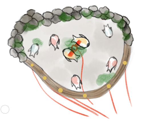
^ visual of how the exterior/circumference of the pond will work - 4 (?) laser cut pieces of wood stacked on top of each other. the layers of plastic will be placed between these layers and trimmed to size
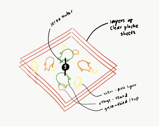
^ servo motor is in the middle (have to figure out how to trim the sheet to make it fit perfectly)

top view example - rocks/pebbles + greens will be added for decoration.
orange dots on the edge represents LEDs
servo motor + LEDS connected to Arduino and triggered by PIR motion sensor.
1 note
·
View note
Text
Remote PIR Motion Sensor
#include <SPI.h> #include <Wire.h> #include <Adafruit_GFX.h> #include <ESP_Adafruit_SSD1306.h> #define OLED_RESET 4 Adafruit_SSD1306 display(OLED_RESET); extern "C" { #include "user_interface.h" } #include <ESP8266WiFi.h> #include <ESP8266WebServer.h> #define WIFI_SSID "PUTYOURSSID" #define WIFI_PWD "PUTYOURPASSWD" ESP8266WebServer server(80); // HTML #define HTML_HEADER "<!doctype html>"\ "<html><head><meta charset=\"UTF-8\"/>"\ "<meta name=\"viewport\" content=\"width=device-width\"/>"\ "</head><body>" #define HTML_FOOTER "</body></html>" byte x=0; void setup() { // put your setup code here, to run once: pinMode(3, INPUT); //GPIO3=RxD pinMode(15, OUTPUT); //3V3B enable digitalWrite(15, HIGH); Wire.begin(4,5); //SDA,SCL = IO4,IO5 display.begin(SSD1306_SWITCHCAPVCC, 0x78>>1); // OLED ADDRESS display.clearDisplay(); display.setTextColor(WHITE); display.setTextSize(1); display.setCursor(0,0); display.println("\nWeb Server"); display.display(); WiFi.begin(WIFI_SSID, WIFI_PWD); // Wait until WiFi is connected while(WiFi.status() != WL_CONNECTED){ delay(1000); display.print("."); display.display(); } //display.println(""); display.clearDisplay(); display.setCursor(0,0); display.println("Connected!"); display.println("IP Address:"); display.println(WiFi.localIP()); display.display(); delay(3000); // Setup WebServer Handlers server.on("/", [](){ //String html = HTML_HEADER "<h1>NodeMCU!</h1>" HTML_FOOTER; String html = HTML_HEADER "<h1>PIR Motion Sensor: "; if ( x == 0) { html += "There is nobody."; } else { html += "There is somebody!"; } html += HTML_FOOTER; server.send(200, "text/html", html); }); server.begin(); } void loop() { // put your main code here, to run repeatedly: display.setTextSize(2); display.setCursor(0,40); display.setTextColor(BLACK); //clear the previous display display.println(x); display.setCursor(0,40); display.setTextColor(WHITE); //a = system_adc_read(); x = digitalRead(3); //result of PIR sensor display.println(x); display.display(); delay(1000); server.handleClient(); }
2 notes
·
View notes
Text

Artist Statement
‘Mutate’ is a dynamic installation which reacts to the user’s kinetic energy (input) and translates this raw data to produce the movement of an XY plotter (process) which creates an interactive display of articulate and engaged motions, presented through a magnetic ferrofluid (output). We often see ourselves through mirrors, photos, and reflective surfaces, but something that we tend to overlook is the physical representation of ourselves through movement and energy. Everyone’s kinetic energy is different, and that is what ‘Mutate’ aims to portray.
The use of a magnetic substance is also an enigmatic concept, as the earth’s core contains a geomagnetic field that extends from the earth’s interior out into space. For the user to be able to control such a cryptic substance through their own kinetic energy is a complex experience made possible through ‘Mutate’. The design is produced through Arduino software, which uses Grbl and Gcode to control the movement of an XY plotter. An augmented visualisation is created through the input of kinetic energy, which is captured through a PIR motion sensor and allows for the mutation and movement of a magnetic ferrofluid - encased within an acrylic tank.
2 notes
·
View notes
Text
In Tinkercad circuits, choose sensor substitutes.

Tinkercad Circuits has a small library of frequently used electronic parts by design. Beginners may easily explore the complexities of the electrical world without feeling overwhelmed thanks to this curation. The drawback is that you can't build an identical replica of your circuit in the simulator if you're looking for a particularly specific part number or version of a sensor that isn't there in the parts drawer.
Fortunately for all of us, there's usually a solution to represent your missing component by using a similar one instead. A few major groups of sensors contain many similar sensors. You can choose an appropriate replacement for your Tinkercad Circuit with the aid of this tutorial.
Digital sensors

As they are activated, analogue sensors provide a changing voltage and resistance. Potentiometers are the most common sort of analogue sensor, but other more specialised varieties exist as well, such as flex sensors, photoresistors, microphones, some temperature sensors, force-sensitive resistors (pressure sensors), piezo components, and some IR distance sensors. Analogue inputs can be read using Arduino's analogRead() function or Tinkercad's "read analogue pin" block.
We advise using a potentiometer or TMP36 temperature sensor as an alternative in Tinkercad circuits if the analogue sensor you wish to use has three pins, as they both have three pins (power, ground, and signal). The TMP36 requires a regulated power supply voltage (2.7-5.5V), whereas a potentiometer is an only resistive sensor. This is an important distinction to make.
The only viable alternative in Tinkercad Circuits if your analogue sensor only has two pins is a two-pin photoresistor (the piezo element in Tinkercad Circuits can only be used as an output).
Electronic Sensors

High/low voltage signals and more complicated digital signals are the two primary categories of digital sensors.
Pushbuttons, switches, tilt ball sensors, magnetic reed switches, PIR motion sensors, and vibration switches are a few examples of sensors in this category. Try one of the many switches and pushbuttons available in Tinkercad Circuits, but also have a look at the tilt sensor and PIR motion sensor, whose simulations might more precisely resemble whatever digital sensor you are trying to replicate. Using digitalRead();, Arduino may read signals with high or low voltage. "Read digital pin" is the Tinkercad block for digital inputs. Launch the simulation below, then click on each sensor to see what happens:
The swap possibilities are more constrained for more sophisticated sensors that make use of data protocols like i2c. There isn't a component that can act as your i2c device, yet you might be able to use the extra library by putting it into your Arduino sketch.
Further Resources
When you make a substitution, we advise using the annotation tool to put notes on your circuit. Even though you couldn't illustrate the precise correct component, this can still aid in communicating the intent.
Don't overlook Tinkercad Circuits' starters, which can get you up and going with several fundamental sensors very quickly (in the components drawer).
Try out our beginner-level Arduino courses using Tinkercad Circuits to learn more about how to add sensors into your Arduino projects.
Send the team your requests for components, please! Although we deliberately limit the number of available components, we are constantly considering what we can add to make Tinkercad Circuits even better. Your criticism is a gift. I'm grateful.
1 note
·
View note
Text
Midterm Project: The Video Game Controller
Introduction: The game initially was supposed to be a game where the objective is to catch water in a bucket for a town experiencing a drought
Sensor Rationale: My sensor was the PIR motion sensor, the rationale was to resemble a VR game where the user would be controlling the direction of the bucket depending on which sensor they activated
Controller Design & Construction: To set up two PIR motion sensors with my Arduino and breadboard, I started by gathering everything I needed: an Arduino board, two PIR sensors (like the HC-SR501), a breadboard, and some jumper wires. Each PIR sensor has three pins (VCC for power, GND for ground, and OUT for the signal). Since the sensor pins are small and not ideal for directly plugging into a breadboard, I decided to solder jumper wires directly to the pins. I soldered one wire to each pin and then I plugged them into the breadboard . I connected both VCC wires to the 5V pin on the Arduino and both GND wires to the Arduino’s GND pin. Then, I connected the OUT wire from the first PIR sensor to digital pin 7 and the OUT wire from the second sensor to digital pin 4.
Arduino Code :
const int pirPin1 = 5; // First PIR sensor connected to pin 7
const int pirPin2 = 4; // Second PIR sensor connected to pin 8
int pirState1 = LOW; // State of PIR sensor 1
int pirState2 = LOW; // State of PIR sensor 2
int lastPirState1 = LOW; // Last state of PIR sensor 1
int lastPirState2 = LOW; // Last state of PIR sensor 2
void setup() {
pinMode(pirPin1, INPUT); // Set PIR sensor 1 pin as input
pinMode(pirPin2, INPUT); // Set PIR sensor 2 pin as input
Serial.begin(9600); // Start serial communication at 9600 baud rate
}
void loop() {
pirState1 = digitalRead(pirPin1); // Read state of PIR sensor 1
pirState2 = digitalRead(pirPin2); // Read state of PIR sensor 2
Serial.print(pirState1);
Serial.print (",");
Serial.println(pirState2);
// Save the current state as the last state for the next loop
lastPirState1 = pirState1;
lastPirState2 = pirState2;
// Delay between readings to stabilize sensor input
}
P5.js Game Code (Well-Commented):
let serial; let latestData = "waiting for data"; // To hold the PIR sensor data
// Game variables let basketX, basketY, basketWidth, basketHeight; let fallingRaindrops = []; let score = 0;
let cloudPositions = []; // Store cloud positions for moving clouds
let targetX = 0; // Target x position for sensor 1 (smooth movement) let targetSpeed1 = 0.1; // Smooth speed for sensor 1 (change this value for more smoothness) let targetSpeed2 = 2; // Slower speed for sensor 2 (change this value for slower movement)
function setup() { createCanvas(windowWidth, windowHeight);
// Initialize the serial object for Arduino serial = new p5.SerialPort();
// List all available serial ports serial.list();
// Open the serial port (replace 'COM5' with your correct port) serial.open('COM5');
// Register event handlers for serial communication serial.on('connected', serverConnected); serial.on('list', gotList); serial.on('data', gotData); serial.on('error', gotError); serial.on('open', gotOpen); serial.on('close', gotClose);
// Set initial values for the basket (bucket) basketX = width / 2; basketY = height - 50; basketWidth = 100; basketHeight = 40;
// Initial raindrop setup setInterval(generateRaindrop, 1000); // Add a new raindrop every second
// Initialize cloud positions for (let i = 0; i < 5; i++) { cloudPositions.push({ x: random(width), y: random(height / 2), // Clouds stay at the top part of the screen speed: random(0.5, 1.5) }); } }
function serverConnected() { print("Connected to Server"); }
function gotList(thelist) { print("List of Serial Ports:"); for (let i = 0; i < thelist.length; i++) { print(i + " " + thelist[i]); } }
function gotOpen() { print("Serial Port is Open"); }
function gotClose() { print("Serial Port is Closed"); latestData = "Serial Port is Closed"; }
function gotError(theerror) { print(theerror); }
function gotData() { let currentString = serial.readLine(); // Read incoming data from the serial port if (currentString) { currentString = currentString.trim(); // Trim the string properly if (currentString) { console.log("Received data:", currentString); // Debug: show received data latestData = currentString; // Update the latest data received ("0,0", "1,0", "0,1", "1,1") } } }
function draw() { // Draw the background as a cloudy town drawCloudyTownBackground();
// Draw the bucket (using a rounded rectangle and an ellipse for the base) fill(255, 0, 0); noStroke();
// Draw the bottom of the bucket as a half ellipse arc(basketX + basketWidth / 2, basketY + basketHeight / 2, basketWidth, basketHeight, 0, PI, CHORD);
// Draw the top of the bucket as a rectangle (body) rect(basketX, basketY - basketHeight / 2, basketWidth, basketHeight / 2);
// Update basket movement based on PIR sensor input updateMovement();
// Draw and update raindrops for (let i = fallingRaindrops.length - 1; i >= 0; i--) { let raindrop = fallingRaindrops[i]; fill(0, 0, 255); // Draw the raindrop as an ellipse with more vertical elongation ellipse(raindrop.x, raindrop.y, raindrop.sizeX, raindrop.sizeY); raindrop.y += raindrop.speed; // Make the raindrop fall// Check if the raindrop hits the bucket if (raindrop.y + raindrop.sizeY / 2 >= basketY && raindrop.x > basketX && raindrop.x < basketX + basketWidth) { score++; // Increment score when a raindrop is caught fallingRaindrops.splice(i, 1); // Remove the raindrop after it is caught } // If the raindrop falls out of the screen, remove it if (raindrop.y > height) { fallingRaindrops.splice(i, 1); }
}
// Display score fill(0); textSize(24); text("Score: " + score, 10, 30); }
// Function to update movement based on PIR sensor data function updateMovement() { if (latestData) { // Parse the latest data to get pirState1 and pirState2 let states = latestData.split(","); if (states.length < 2) return; // Ensure there are two elements in the arraylet pirState1 = int(states[0].trim()); // First PIR sensor state let pirState2 = int(states[1].trim()); // Second PIR sensor state // Debugging output to confirm sensor values console.log("1", pirState1, "2", pirState2); // Update basket movement based on sensor states if (pirState1 === 1) { // Move basket to the right if motion is detected on sensor 1 basketX += 10; } if (pirState2 === 1) { // Move basket to the left if motion is detected on sensor 2 basketX -= 10; } // Prevent the basket from moving off the canvas basketX = constrain(basketX, 0, width - basketWidth);
} }
// Function to generate a falling raindrop at a random x position function generateRaindrop() { let raindrop = { x: random(width), y: 0, // Start from the top sizeX: random(10, 15), // Random width for raindrop sizeY: random(20, 40), // Random height for raindrop (more elongated) speed: random(3, 6) // Falling speed }; fallingRaindrops.push(raindrop); }
// Function to draw a cloudy town background function drawCloudyTownBackground() { // Draw sky background(135, 206, 235); // Light blue sky color
// Draw the clouds for (let i = 0; i < cloudPositions.length; i++) { let cloud = cloudPositions[i]; fill(255, 255, 255, 180); // White, semi-transparent clouds noStroke(); ellipse(cloud.x, cloud.y, 200, 80); // Big cloud ellipse(cloud.x + 60, cloud.y - 20, 150, 60); // Smaller cloud part ellipse(cloud.x - 60, cloud.y - 20, 150, 60); // Smaller cloud part cloud.x += cloud.speed; // Move the cloud// If the cloud goes off the screen, reset its position if (cloud.x > width + 100) { cloud.x = -100; }
}
// Draw the city skyline (simple buildings) fill(50, 50, 50); // Dark gray for buildings rect(0, height - 150, 100, 150); // Building 1 rect(150, height - 200, 80, 200); // Building 2 rect(250, height - 180, 100, 180); // Building 3 rect(400, height - 250, 120, 250); // Building 4 rect(550, height - 160, 90, 160); // Building 5 }
Communication Protocol Details: This p5.js code connects to an Arduino using a serial port to receive live data, like numbers from sensors. It uses the p5.SerialPort() library to open the connection (on COM5) and listen for different events, like when the connection is opened, closed, or when new data arrives. When the Arduino sends data, the program reads it as a line of text, removes any extra spaces, and splits the text into two values using a comma. These values are saved as value0 and value1, which can be used in the draw() function to control what’s shown on the screen—like the position or behavior of shapes. This setup lets the webpage respond to what the Arduino senses in real time.
User Instructions: Each motion sensor determines if the bucket moves left, right, or remains stagnant. Using the left sensor, move your hand in front of it to move the bucket to the left. Using the right sensor, move your hand in front of it to move the bucket to the right. If both sensors are activated at the same time, the bucket will stay in the place it is in until one sensor halts detection.
Challenges & Solutions: Challenges included setting up the sensor and activating it. The PIR motion sensors are sensitive so trying to get them to turn off and on was a difficult task. However, I managed to tweak the settings to make the time and sensitivity low. However, that also made the sensor delayed, resulting in the reaction time glitchy in the game.
Future Enhancements: Soldering from the beginning and making sure my code is as simple as possible would help me in the future. I think also changing the game could make more sense for the sensor.
Conclusion: I learned a lot in the end, and even used AI to help me with code and wiring. Next time, I hope to use my skills to develop more complex code for p5.js and Arduino so the sensor can be used for a variety of games.
Link to video game:
0 notes
Text
Arduino Projects
Arduino is an open-source electronics platform that allows users to create automated and interactive projects by combining hardware and software. The Arduino IDE (Integrated Development Environment) is used to program the microcontroller boards, which are the foundation of Arduino and include the Arduino Uno, Mega, and Nano. The platform allows users to design projects that range from basic LED flashing to intricate IoT systems thanks to its extensive selection of sensors, actuators, and modules.
Why Choose Arduino for Your Projects?
User-Friendly
Open-Source Ecosystem
Affordability
Versatility
Top Arduino Project Ideas to Inspire You
Automation System for Smart Homes
Use an Arduino to automate your house by utilizing a smartphone app to control appliances, fans, and lights. To build a completely automated home, combine an Arduino with sensors such as temperature or motion sensors.
The weather station
Construct a personal weather station that can track air pressure, temperature, and humidity. For real-time monitoring, use sensors like the DHT11 or BMP180 and send data to the cloud or show it on an LCD.
Robot That Follows Lines
Using an Arduino board, two infrared sensors, and motors, build a robot that follows a line. It's an excellent project for studying control systems and robotics.
Automatic Watering System for Plants
Create a system that automatically waters plants when the soil gets dry by combining an Arduino board with a soil moisture sensor. Perfect for busy plant enthusiasts!
Intelligent Security System
Create a security system that detects invasions and notifies your phone via PIR motion sensors, cameras, and GSM modules.
Game Controller Powered by Arduino
Create a unique game controller with an Arduino board, joysticks, and buttons. For a more engaging experience, add haptic feedback to further improve it.
IoT Energy Tracker
Use sensors to monitor the energy use of your house, and an online dashboard will show the data in real time. For real-world uses, this project combines Arduino and IoT technology.
An avenue for technological discovery and creativity is provided by Arduino projects. Arduino is the ideal platform to start learning electronics and coding, automating your environment, or building robots. Accept the limitless potential, try out concepts, and join the rapidly expanding maker community. Your creativity is the only restriction while using Arduino!
To know more, click here.
0 notes
Text
Creare un sistema di Motion Alarm con Arduino
Se stai cercando un modo per proteggere la tua casa o il tuo ufficio dall'intrusione, un sistema di Motion Alarm basato su Arduino potrebbe essere la soluzione perfetta.
In questo post, ti mostreremo come creare un sistema di Motion Alarm usando Arduino e un sensore di movimento PIR (Passive Infrared Sensor).
Il Motion Alarm in Arduino è un'ottima soluzione per proteggere la tua casa o il tuo ufficio, e con la guida che ti forniremo potrai costruirlo anche tu. Ti mostreremo passo dopo passo come costruire il circuito, come programmare Arduino e come testare il tuo sistema di Motion Alarm.
0 notes
Text
Medal of honor allied assault cheats

#MEDAL OF HONOR ALLIED ASSAULT CHEATS HOW TO#
#MEDAL OF HONOR ALLIED ASSAULT CHEATS MOVIE#
#MEDAL OF HONOR ALLIED ASSAULT CHEATS CODE#
#MEDAL OF HONOR ALLIED ASSAULT CHEATS HOW TO#
There are videos and how to enable cheats in Medal of Honor: Allied Assault, and the expansions. Your player should blow up and say, 'What did you do that for?' HintsTake careful aim and go for head shots when you can.Don't forget that grenades can do the trick when firearms can't.A stealthy approach is best. I unfortunately can't post links in posts.
#MEDAL OF HONOR ALLIED ASSAULT CHEATS MOVIE#
We hope that you are enjoying your visit to Free Game Cheats and look forward to your return for more of the best cheat codes.DirectionsCheat codesUnlimited ammunition BADCOPSHOWRapid fire ICOSIDODECReflecting shots GOBLUEMultiplay power-ups DENNISMODEWire frame mode TRACERONAmerican movie mode SPRECHENMultiplayer charactersWinston Churchill FINESTHOURVelociraptor SSPIELBERGWilliam Shakespeare PAYBACKBismark The Dog WOOFWOOFWerner Von Braun ROCKETMANWolfgang HOODUPUnlock 'Making of.' FeatureLevel 1 INVASIONLevel 2 BIGGRETALevel 3 DASBOOTLevel 4 STUKALevel 5 KOMETLevel 6 TWOSIXTWOLevel 7 MISSLEAGUELevel 8 VICTORYDAYKill YourselfPress R1, R2, L2, R1, R1, R1, R2, L2, L1, L1 then press Square quickly.
#MEDAL OF HONOR ALLIED ASSAULT CHEATS CODE#
Dikarenakan semua benda yang memancarkan atau menghasilkan energi radiasi, akan terdeteksi oleh sensor ini pada saat infra merah dari sensor PIR mendeteksi dengan perbedaan suhu tertentu.Ĭheat Code InfoCategory: PlayStationRating: 0Contributor: n/aThe following cheat codes are for Medal Of Honor on the PlayStation platform. Drive various assault vehicles, always charging onwards to victory. Call in artillery and air strikes against the opposing forces and keep your squad away from the jaws of defeat and despair. Aplikasi penggunaan dari sensor PIR ini difungsikan dalam aplikasi proyek detektor pergerakan. Medal of Honor: Allied Assault War Chest is a treasure trove of historical battles presented as a gritty World War II action FPS. In the comments, you can find explanation of the whole code. Now it’s time to upload the program to Arduino. You will need 5 Jumper wires to connect everything, all of these wires should have male-female connectors. First thing we have to do, before uploading the program is getting the connections ready. This pin will be the INPUT pin for Arduino. The output pin of the PIR Sensor is connected to the 2 nd digital pin of Arduino. We have powered the PIR sensor using he 5V Rail of the Arduino. MAIN CHEAT CODES To enable cheat mode, start the game with the following parameters: +set uiconsole 1 +set cheats 1 +set thereisnomonkey 1. The circuit Diagram for arduino motion detector project by interfacing Arduino with PIR module and blinking an LED/Buzzer is shown in the below image. This page contains a list of cheats, codes, Easter eggs, tips, and other secrets for Medal of Honor: Allied Assault Spearhead for PC.If you've discovered a cheat you'd like to add to the page, or. MoH:AAAllied AssaultaultaultaultAllied AssaultaultAllied AssaultaultAllied AssaultAllied AssaultaultaultAllied AssaultAllied AssaultAllied AssaultAllied AssaultaultaultAllied AssaultaultAllied. Ini adalah cara yang bagus untuk anda mempelajari dasar-dasar menggunakan input digital pada arduino dari sebuah sensor dan output dalam praktek kali ini menggunakan Alrm sebuah Buzzer. Belajarrobot: Sensor Pir dengan Arduino untuk deteksi gerak manusia - Dalam proyek sederhana ini, saya akan membuat sebuah alarm menggunakan sensor PIR (pasif inframerah) dan pemrograman Arduino Uno.
0 notes
Text
Arduino Projekt: PIR & RFID Alarmanlage

In diesem Projekt möchte ich die bereits erzeugte und vorgestellte Arduino Projekt: Alarmanlage mit RFID Steuerung um einen Pyroelektrischer Infrarot Motion Sensor (PIR) erweitern.

Alarmanlage mit PIR ind RFID Modul
Warum das Projekt PIR & RFID Alarmanlage?
Das Projekt entstand aus einem Kommentar zum Beitrag Arduino Projekt: Alarmanlage mit RFID Steuerung der Leser hatte mich hier gefragt wie denn ein PIR Sensor in die Schaltung integriert werden kann. Dieses habe ich zum Anlass genommen das Projekt neu aufzubauen und zwei PIR Sensoren zu integrieren. Des Weiteren verwende ich nun auch eine RGB SMD Led statt zwei einzelne LEDs somit kann ich noch weitere Zustände farblich darstellen.
Benötigte Bauteile / Bauelemente
Bezeichnung Preis Link Arduino Leonardo (oder vergleichbar) 4,50 € ebay.de RFID Modul - RC522 3,50 € ebay.de PIR Modul - HC-SR505 1,09 € ebay.de PIR Modul - HC–SR501 2,85 € ebay.de NeoPixel Modul 4,44 € ebay.de Piezo Buzzer 1,40 € ebay.de 400 PIN Breadboard 3,85 € ebay.de Breadboardkabel 1,90 € ebay.de

Benötigte Bauelemente / Bauteile für die Alarmanlage mit zwei PIR Sensoren
Aufbau
Der Aufbau ist auf einem Breadboard, lötfrei und schnell erledigt. Die verbauten Module benötigen 10 digitale Pins somit reicht ein Arduino Leonardo völlig aus. Sicherlich könnte man auch hier einen Arduino UNO oder sogar einen Arduino Nano verwenden, jedoch habe ich sehr gute Erfahrungen mit dem Leonardo gemacht. Anschluss Modul Pin Arduino Leonardo RFID Modul - RC522 SDA D10 SCK D19 MOSI D17 MISO D18 IRQ -bleibt frei- GND GND RST Reset 3.3V 3.3V PIR Modul - HC-SR505 + 5V OUT D5 - GND PIR Modul - HC–SR501 VCC 5V OUT D6 GND GND NeoPixel Modul GND GND RED D4 GREEN D2 BLUR D7 Piezo Buzzer SIG D3 VCC 5V GND GND
Schaltplan

Aufbau der Schaltung auf dem Steckbrett
Quellcode
Für das kompilieren und den Betrieb des Quellcodes wird die Bibliothek für das RFID Modul benötigt, diese kannst du von der Wiki Seite Electrodragon.com herunterladen. #include #include //RGB LED #define BLUE_LED 7 /* PIN für die blaue LED */ #define RED_LED 4 /* PIN für die rote LED */ #define GREEN_LED 2 /* PIN für die grüne LED */ //Piezo Buzzer #define BUZZER 3 /* PIN für den Buzzer */ //RFID Modul - RC522 #define SS_PIN 10 /* PIN SDA für das RFID Modul */ #define RST_PIN 9 /* PIN RST für das RFID Modul */ RFID rfid(SS_PIN, RST_PIN); String ids = {"453B56D16", "8C3B3924AA1"}; //Zugelassene ID's //PIR Modul HC-SR505 #define PIR505_PIN 5 /* PIN OUT für das PIR Modul HC-SR505 */ //PIR Modul HC-SR501 #define PIR501_PIN 6 /* PIN OUT für das PIR Modul HC-SR501 */ boolean isActive = false; void setup() { Serial.begin(9600); pinMode(PIR501_PIN, INPUT); pinMode(PIR505_PIN, INPUT); pinMode(BLUE_LED, OUTPUT); /* Setzt den PIN für die blaue LED als Ausgang. */ pinMode(RED_LED, OUTPUT); /* Setzt den PIN für die rote LED als Ausgang. */ pinMode(GREEN_LED, OUTPUT); /* Setzt den PIN für die grüne LED als Ausgang. */ pinMode(BUZZER, OUTPUT) ; /* Setzt den PIN für den Piezo Buzzer als Ausgang. */ SPI.begin(); rfid.init(); } void loop() { boolean foundId = false; if (rfid.isCard() && rfid.readCardSerial()) { Serial.println("drin"); String serial = parseId(rfid); //Ausgabe der ID auf dem Seriellen Monitor Serial.println("RFID Nummer: " + serial); //Schleife zum pruefen der erkannten RFID. int counter = 0; for (counter = 0; counter < sizeof(ids) - 1; counter++) { //Wenn die RFID bekannt ist so soll die Alarmanlage aktiviert bzw. deaktiviert werden. if (serial == ids) { isActive = !isActive; foundId = true; break; } } Serial.println(foundId); } if(isActive){ blinkActiveLED(); int pirHC505 = digitalRead(PIR505_PIN); int pirHC501 = digitalRead(PIR501_PIN); if(pirHC505 == HIGH || pirHC501 == HIGH){ tone(BUZZER, 500, 50); noTone(BUZZER); } } if(foundId){ lightUpLED(0, 255, 0); } else { lightUpLED(255, 0, 0); } delay(1500); } //Liesst eine ID aus dem Modul //und gibt diese als String zurueck. String parseId(RFID rfid) { String result = ""; int position = 0; for (position = 0; position Read the full article
1 note
·
View note