#Pin diode switch
Explore tagged Tumblr posts
Visit Tumblr Blog
Explore Tumblr blogs with no restrictions, modern design and the best experience.
Last Seen Tumblr Blogs


Fun Fact
1,644 Tumblr posts in 1 second.
Text
https://www.futureelectronics.com/p/semiconductors--discretes--diodes--switching/bas21ht1g-onsemi-5159711
RF switches, Fast switching diode, Pin diode switch, high-speed switch
BAS21H Series 250 V 200 mA Surface Mount Switching Diode - SOD-323
#Diodes#Switching Diodes#BAS21HT1G#onsemi#RF switches#Fast switching diode#Pin diode switch#high-speed switch#Diode module#Band Switching Diodes#Modular switch#radiofrequency receivers#Band#circuit
1 note
·
View note
Text
https://www.futureelectronics.com/p/semiconductors--discretes--diodes--switching/bas21ht1g-onsemi-7218829
What is a switching diode, fast switching diode, Pin diode switch
BAS21H Series 250 V 200 mA - SOD-323 Surface Mount Switching Diode
#onsemi#BAS21HT1G#Diodes#Switching Diodes#fast switching diode#Pin diode switch#Surface Mount Switching Diode#RF switches#on off switch#reverse voltage#High-speed switching diodes#Open switch#high-speed switch
1 note
·
View note
Text
https://www.futureelectronics.com/p/semiconductors--discretes--diodes--switching/sbav99lt1g-onsemi-5152166
What is a switching diode, Fast switching diode, Semiconductor diode, module
BAV99 Series 70 V 715 mA Surface Mount High Speed Switching Diode - SOT-23
#Diodes#Switching Diodes#BAV99LT1G#onsemi#Fast#Semiconductor diode#module#Power switching diodes#High-speed switch#RF switches#switching diode#Diode switch#pin diode switch#Surface Mount High Speed Switching Diode
1 note
·
View note
Text
https://www.futureelectronics.com/p/semiconductors--discretes--diodes--switching/sbav99lt1g-onsemi-8159990
High speed switching diode, diode switching times, diode switching times
BAV99 Series 70 V 715 mA Surface Mount High Speed Switching Diode - SOT-23
#onsemi#BAV99LT1G#Diodes#Switching Diodes#High speed#diode switching times#pin diode switch#Dual#switching diode vs Zener diode#reverse voltage#Solid State Switches#switching operation
1 note
·
View note
Text
https://www.futureelectronics.com/p/semiconductors--discretes--diodes--switching/1n4148wq-7-f-diodes-incorporated-7037709
Diodes Incorporated, 1N4148WQ-7-F, Diodes, Switching Diodes
1N4148W Series 400 mW 100 V 300 mA SMT Switching Diode - SOD-123
#Diodes Incorporated#1N4148WQ-7-F#Diodes#Switching Diodes#Dual#application#radiofrequency#RF switches#ultra high speed#Pin diode switch#signal switching diode#Switching Diode#what is a switching diode#Diode switch
1 note
·
View note
Text
https://www.futureelectronics.com/p/semiconductors--discretes--diodes--switching/1n4148ws-7-f-diodes-incorporated-3369816
High Speed Switching Diode, fast switching diode module
1N4148W Series 2 A 100 V 400 mW Surface Mount Fast Switching Diode - SOD-123
#Diodes Incorporated#1N4148W-7-F#Diodes#Switching Diodes#High Speed#fast switching diode module#Power supplies#radiofrequency receivers#pin diode switch#Fast switching diode#power management circuits#RF switches
1 note
·
View note
Text
https://www.futureelectronics.com/p/semiconductors--discretes--diodes--switching/1n4148w-7-f-diodes-incorporated-4129355
Diodes Incorporated, 1N4148W-7-F, Diodes, Switching Diodes
1N4148W Series 2 A 100 V 400 mW Surface Mount Fast Switching Diode - SOD-123
#Diodes Incorporated#1N4148W-7-F#Diodes#Switching Diodes#Power supplies#chip#higher switching speed#pin diode switch#Fast#digital logic circuit#Small signal diode#High-speed switching#Small Surface-Mounted#Microwave diode
1 note
·
View note
Text


Leftovers & layout - WLED board revision A completed!
Sunday night, Babyada went to bed early, so we finished the capture and layout of our WLED board. Thanks to all the suggestions, we were able to implement quite a few!
For power, use USB C PD with switch-select or DC up to 24V; they are diode-OR'd together with PMEG3050
https://www.digikey.com/short/zv22b0pq
into a massive 5A 24V fuse
https://www.digikey.com/short/43qwwtwm
For the 5V regulator, we picked NCP718ASN500T1G
https://www.digikey.com/short/bb9ncc0n
- it's linear, but we don't need a lot of current at 5V. For 3.3V, we went with our trusty TPS54202
https://www.digikey.com/short/c1wnnf94
Upon request, we kept the ICS-43434 I2S microphone
https://www.digikey.com/short/28zwrrhz
and added an IR 38KHz receiver. For external connectivity, there's an ADC/DAC/GPIO #27 breakout on a JST SH 3-pin and I2C on a StemmaQT/Qwiic 4-pin.
We also added a 2x3 breakout header with 3V, GND, and 3 more GPIO so you could connect an external microphone, IR receiver, buttons, or rotary encoder. The terminal blocks have three 5V level-shifted outputs with 100 ohm in-line resistors and power/ground pairs for each. If you need just one more LED strand, the fourth 5V signal is on the 2x3 block.
Rounding out the design are four mounting holes, a reset button, GPIO #0 user button, GPIO LED, and an individual NeoPixel, which could be useful for testing. It's still pretty small, 2" x 1.3". With an ESP32-Mini module, we can pick a PCB or wFL antenna port, and it's an easy swap to make it use an ESP32-Pico, which has 2MB PSRAM.
Whatcha think - anything else we should add or watch out for?
#wled#esp32#electronics#pcbdesign#electronicsproject#makerlife#hardwarehacking#openhardware#diytech#electronicsengineering#usbc#miccontroller#neopixel#iotdevices#irreceiver#powersupplydesign#smalldesign#esp32mini#hardwarelayout#buildprogress#techinnovation
41 notes
·
View notes
Text
Today I got my pockettype kit I ordered from mechboards and BAM in one morning I put it all together. Here it is next to my Gherkin.
40 4 pin switches 40 diodes and I got it all done really fast because I'm a decently uick solderer now.

2 notes
·
View notes
Text
Relay operated power button

What you need:
a 5V relay module
Raspberry Pi
a bunch of cables
Explanation:
A power button on a computer case lets electricity flow between two power pins upon it being pressed, which is when the motherboard detects the button is pressed and reacts accordingly.

A relay is a specific kind of switch which lets electricity flow conditionally upon the flow of electricity in another circuit. The voltages involved both in motherboard power pins and on Raspberry Pi are generally low to not damage both, but we're taking extra precautions to electrically separate them both.
"5V relay module" here means that 5V is the voltage that is required for the relay module to work, while the controlling voltage can be lower. It being relay module it means it also has a flyback diode we'd otherwise have to provide ourselves.

Raspberry Pi's GPIO pins are programmable and can be controlled through Python code, and operate on 3.3V. Raspberry Pi also provides 5V output, but this one is not controllable.
By
connecting a power button to rPi GPIO pins
connecting the 5V voltage output pin from rPi to the relay module's Vcc input pin
connecting the ground pin from rPi to the relay module's groud pin
connecting programmable GPIO pins as the relay module's input pin
connecting the relay module's outputs (the normally open one and the ground) to the motherboard power pins
running some code on rPi
We can extend the power button functionality so Raspberry Pi can turn on and off our computer, while also still keeping the power button working.
Which is what I use to remotely turn on my computer on, by SSHing to rPi and running a script to turn the PC on while I'm away from home.
Why not Wake-On-LAN?
Wake-On-LAN has restrictions which makes it not as reliable as it could be, for example:
The ability to wake from a hybrid shutdown state (S4) (aka Fast Startup) or a soft powered-off state (S5) is unsupported in Windows 8 and above
The code and explanation for it in Part 2, when I get to writing it.
17 notes
·
View notes
Text
Digitally Controlled Attenuators Market: Trends, Opportunities, and Forecast 2025–2032

MARKET INSIGHTS
The global Digitally Controlled Attenuators market size was valued at US$ 623.7 million in 2024 and is projected to reach US$ 1.04 billion by 2032, at a CAGR of 7.6% during the forecast period 2025-2032.
Digitally controlled attenuators are specialized RF components that dynamically adjust signal amplitude through electronic control interfaces. These devices utilize semiconductor technologies like PIN diodes and GaAs MESFETs to provide precise, programmable attenuation levels across wireless communication systems. The product landscape includes fixed attenuators for stable loss applications and step attenuators for variable signal conditioning.
Market growth is being driven by escalating demand for 5G infrastructure deployment, which requires sophisticated signal conditioning components. The cellular infrastructure segment accounted for 38% of total application share in 2024. Furthermore, increasing adoption in test equipment and satellite communications is contributing to expansion. Key industry players like Analog Devices and Qorvo are enhancing product portfolios through R&D investments – Analog Devices recently launched its ADRF5721 silicon digital attenuator with 0.5dB step resolution for 5G applications. Other major competitors include MACOM, Skyworks Solutions, and Murata Manufacturing.
MARKET DYNAMICS
MARKET DRIVERS
Proliferation of 5G and IoT Technologies Boosting Demand for Digitally Controlled Attenuators
The rapid global rollout of 5G networks is creating unprecedented demand for digitally controlled attenuators (DCAs). As 5G operates across multiple frequency bands (sub-6 GHz and mmWave), these components are essential for signal conditioning in base stations, small cells, and mobile devices. The worldwide 5G infrastructure market is projected to grow at over 50% CAGR through 2030, with over 1.7 billion 5G subscriptions expected by 2026. DCAs play a critical role in managing signal strength across these networks while maintaining signal integrity. Furthermore, the Internet of Things (IoT) ecosystem is expanding rapidly, with over 29 billion connected devices anticipated by 2030, creating additional demand for precise RF signal control components across industrial and consumer applications.
Advancements in Aerospace and Defense Applications Driving Premium Attenuator Solutions
Modern defense electronic systems, including radar, electronic warfare, and satellite communications, increasingly require high-performance digitally controlled attenuators with wide dynamic ranges and fast switching speeds. Global defense spending has risen to over $2 trillion annually, with electronic warfare systems constituting a growing portion. These applications demand attenuators that can operate reliably in extreme environmental conditions while maintaining precise signal control. Recent developments include DCAs capable of handling frequencies up to 40 GHz with switching speeds under 50 nanoseconds and attenuation ranges exceeding 60 dB. Such performance characteristics are critical for next-generation phased array radar systems and satellite communication payloads.
MARKET RESTRAINTS
Complex Design Requirements and High Development Costs Limiting Market Expansion
The development of advanced digitally controlled attenuators presents significant technical challenges, particularly for high-frequency applications. Designing attenuators that maintain precise control while minimizing insertion loss and VSWR across wide frequency ranges requires specialized engineering expertise and sophisticated simulation tools. Prototyping and testing costs for millimeter-wave DCAs can exceed $100,000 per design iteration, creating barriers to entry for smaller manufacturers. Additionally, the need for customized solutions for specific applications further complicates production scaling and inventory management, with lead times for specialized components often exceeding 12 weeks.
MARKET CHALLENGES
Supply Chain Disruptions and Component Shortages Impacting Production Timelines
The semiconductor supply chain crisis continues to affect production of digitally controlled attenuators, particularly for devices requiring specialized GaAs and SOI wafers. Lead times for certain critical components have extended to 40+ weeks, forcing manufacturers to maintain higher inventory levels. This situation is exacerbated by geopolitical tensions affecting semiconductor supply chains, with export controls limiting access to advanced fabrication technologies. Many manufacturers are now investing in dual-sourcing strategies and redesigning products to accommodate alternative components, but these solutions often involve trade-offs in performance characteristics.
MARKET OPPORTUNITIES
Emerging Millimeter Wave and THz Applications Creating New Growth Avenues
The development of 6G technologies and terahertz communication systems is opening new opportunities for digitally controlled attenuator manufacturers. While commercial 6G deployment remains years away, research indicates that these systems will operate in frequency bands from 100 GHz to 1 THz, requiring entirely new approaches to signal conditioning. Several major technology firms and research institutions have already demonstrated experimental 6G links, creating early demand for test and measurement solutions. Furthermore, emerging applications in quantum computing, advanced medical imaging, and security screening at THz frequencies will require novel attenuator designs with exceptional linearity and dynamic range.
DIGITALLY CONTROLLED ATTENUATORS MARKET TRENDS
5G Deployment and Wireless Communication Expansion Driving Market Growth
The rapid global deployment of 5G networks is significantly boosting demand for digitally controlled attenuators (DCAs), which play a critical role in signal conditioning and power management across wireless infrastructure. With over 1.7 billion 5G subscriptions projected worldwide by 2025, RF component manufacturers are scaling production of high-frequency attenuators capable of operating in millimeter-wave bands. Recent advancements in gallium nitride (GaN) and silicon-germanium (SiGe) semiconductor technologies enable DCAs to achieve superior linearity and thermal performance required for 5G base stations. Concurrently, the proliferation of Internet of Things (IoT) devices necessitates precise RF power control solutions, with smart city applications alone expected to deploy over 7 billion connected devices by 2030.
Other Trends
Defense and Aerospace Modernization
Military modernization programs globally are accelerating the adoption of advanced electronically controlled attenuators for radar and electronic warfare systems. Modern phased array radars require digitally programmable attenuation with microsecond switching speeds and extreme temperature stability. The defense sector accounts for approximately 28% of specialty attenuator sales, driven by next-generation electronic countermeasure systems and satellite communication upgrades. Emerging threats in electronic warfare have prompted defense budgets exceeding $2.1 trillion worldwide, with significant allocations for RF subsystem enhancements.
Test & Measurement Equipment Evolution
The increasing complexity of wireless protocols and semiconductor devices is transforming the test equipment landscape, where digitally controlled attenuators provide critical calibration and signal conditioning functions. Automated test systems now demand attenuators with 0.1dB resolution and >100dB dynamic range to validate 5G NR and Wi-Fi 6E devices. Leading manufacturers have introduced DCAs with integrated temperature compensation and non-volatile memory for maintaining calibration settings. Furthermore, the semiconductor test equipment market, valued at over $10 billion annually, increasingly adopts programmable attenuators to handle heterogeneous integration testing requirements for advanced packaging technologies.
COMPETITIVE LANDSCAPE
Key Industry Players
RF Component Manufacturers Drive Innovation to Capture Growing Demand in 5G and IoT Applications
The global digitally controlled attenuators market features a competitive landscape dominated by specialized RF component manufacturers, with Analog Devices and Qorvo emerging as clear market leaders in 2024. These companies have solidified their positions through continuous technological advancements in semiconductor-based attenuation solutions, particularly for 5G infrastructure and defense applications.
Skyworks Solutions and MACOM Technology Solutions hold significant market shares due to their comprehensive product portfolios covering both fixed and step attenuator configurations. Their success stems from strategic focus on high-frequency applications above 6 GHz, where precision digital control is becoming increasingly critical for modern communication systems.
The market is witnessing increased competition from Japanese component suppliers like Murata Manufacturing, whose ceramic-based attenuator designs are gaining traction in compact consumer electronics applications. Meanwhile, specialized firms such as Pasternack Enterprises and Mini-Circuits continue to expand their market presence through focused product development for test and measurement equipment.
Recent industry movements include multiple strategic acquisitions, with Analog Devices strengthening its microwave component capabilities through the purchase of specialty manufacturers. This consolidation trend is expected to accelerate as companies seek to offer more integrated RF front-end solutions.
List of Key Digitally Controlled Attenuator Companies Profiled
Analog Devices, Inc. (U.S.)
MACOM Technology Solutions (U.S.)
Qorvo, Inc. (U.S.)
Murata Manufacturing Co., Ltd. (Japan)
pSemi Corporation (U.S.)
Skyworks Solutions, Inc. (U.S.)
Atlantic Microwave Ltd. (UK)
Pulsar Microwave Corporation (U.S.)
Qualwave Technology Inc. (China)
JFW Industries, Inc. (U.S.)
Planar Monolithics Industries (U.S.)
API Technologies Corp. (U.S.)
Fairview Microwave (U.S.)
Vaunix Technology Corp. (U.S.)
Segment Analysis:
By Type
Fixed Digital Attenuator Segment Leads Market Due to Precise Signal Control in RF Applications
The digitally controlled attenuator market is segmented based on type into:
Fixed Digital Attenuator
Subtypes: Single-bit, Multi-bit configurations
Step Digital Attenuator
Subtypes: 6-bit, 7-bit, and higher resolution variants
Continuous Variable Attenuators
Programmable Attenuators
Others
By Application
Cellular Infrastructure Segment Dominates with Growing 5G Network Deployments
The market is segmented based on application into:
Cellular Infrastructure
Test Equipment
Satellite Set Top Box
Fiber Optic Telecommunications
Military & Defense Systems
Others
By Frequency Range
Sub-6 GHz Segment Holds Major Share for Telecom and IoT Applications
The market segmentation by frequency includes:
DC to 6 GHz
6-18 GHz
18-40 GHz
Above 40 GHz
By Control Interfaces
Serial Peripheral Interface (SPI) Gains Traction for High-Speed Digital Control
Key interface segments comprise:
Parallel Control
Serial Control
Subtypes: I²C, SPI, USB
Wireless Control
Manual Control
Regional Analysis: Digitally Controlled Attenuators Market
North America North America, led predominantly by the United States, maintains a strong position in the Digitally Controlled Attenuators Market due to its advanced telecommunications infrastructure and defense sector expenditures. The region benefits from significant investments in 5G technology and satellite communication, where precision RF signal control is critical. Additionally, stringent Federal Communications Commission (FCC) regulations drive innovation in high-performance attenuators for commercial and military applications. Key players like Analog Devices and MACOM have a dominant presence here, catering to the needs of cellular infrastructure and test equipment manufacturers. The U.S. government’s focus on electronic warfare modernization further boosts demand, with defense contracts fueling market expansion.
Europe Europe’s market thrives on innovation-driven demand from fiber optic telecommunications and aerospace sectors. Countries like Germany, France, and the U.K. prioritize cutting-edge RF solutions for industrial automation and space applications, supported by EU-funded research programs. With increasing adoption of GaAs-based attenuators for their superior performance in harsh environments, manufacturers such as Qorvo and Murata continue to expand their footprint. Meanwhile, regulatory pressures to minimize signal interference in densely populated urban areas create opportunities for high-precision digital attenuators. However, the market faces challenges due to prolonged semiconductor supply chain disruptions and reliance on imports.
Asia-Pacific As the fastest-growing region, the Asia-Pacific market is propelled by China’s aggressive 5G rollout and India’s expanding telecom networks. The demand for digitally controlled attenuators is surging, particularly in cellular infrastructure and satellite applications, while Japan and South Korea lead in test equipment manufacturing. Though cost sensitivity favors conventional solutions, the shift toward higher-frequency applications (e.g., mmWave for 5G) accelerates the adoption of advanced attenuators. Local manufacturers such as RF-Lambda compete with global leaders, offering cost-efficient alternatives. However, geopolitical tensions and intellectual property concerns pose risks for multinational players operating in the region.
South America This emerging market shows gradual growth, primarily driven by Brazil’s telecom sector and Argentina’s defense modernization efforts. While limited indigenous manufacturing capabilities lead to reliance on imports, increasing fiber optic network deployments present opportunities for step digital attenuators. Economic instability and fluctuating currency values, however, hinder large-scale investments. Despite these challenges, partnerships between global suppliers and local distributors aim to strengthen market penetration, especially for satellite communication and broadcasting applications.
Middle East & Africa The market here remains niche but holds potential due to expanding smart city initiatives in the UAE and Saudi Arabia’s investments in aerospace and defense. Demand for fiber optic telecommunications attenuators is rising, though funding constraints and a fragmented regulatory landscape slow progress. In Africa, minimal telecom infrastructure development restricts growth, but satellite TV and broadcasting applications offer steady demand. Key suppliers like Atlantic Microwave and Pasternack Enterprises target high-value contracts in oil & gas and military sectors, where ruggedized attenuators are essential.
Report Scope
This market research report provides a comprehensive analysis of the global and regional Digitally Controlled Attenuators market, covering the forecast period 2025–2032. It offers detailed insights into market dynamics, technological advancements, competitive landscape, and key trends shaping the industry.
Key focus areas of the report include:
Market Size & Forecast: Historical data and future projections for revenue, unit shipments, and market value across major regions and segments. The global Digitally Controlled Attenuators market was valued at USD 265.8 million in 2024 and is projected to reach USD 412.5 million by 2032, growing at a CAGR of 5.7%.
Segmentation Analysis: Detailed breakdown by product type (Fixed Digital Attenuator, Step Digital Attenuator), application (Cellular Infrastructure, Test Equipment, Satellite Set Top Box, Fiber Optic Telecommunications), and end-user industry to identify high-growth segments.
Regional Outlook: Insights into market performance across North America, Europe, Asia-Pacific, Latin America, and Middle East & Africa. The U.S. market is estimated at USD 78.2 million in 2024, while China is projected to reach USD 92.5 million by 2032.
Competitive Landscape: Profiles of leading market participants including Analog Devices, MACOM, Qorvo, Murata, and Skyworks, covering their product portfolios, market share (top 5 players held 42% share in 2024), and strategic developments.
Technology Trends & Innovation: Assessment of emerging technologies in RF signal processing, integration with 5G infrastructure, and advancements in semiconductor materials like GaAs and GaN.
Market Drivers & Restraints: Evaluation of factors including 5G network expansion, growth in satellite communications, and challenges like supply chain constraints for semiconductor components.
Stakeholder Analysis: Strategic insights for component manufacturers, system integrators, and investors regarding market opportunities and technological evolution.
Related Reports:https://semiconductorblogs21.blogspot.com/2025/06/fieldbus-distributors-market-size-and.htmlhttps://semiconductorblogs21.blogspot.com/2025/06/consumer-electronics-printed-circuit.htmlhttps://semiconductorblogs21.blogspot.com/2025/06/metal-alloy-current-sensing-resistor.htmlhttps://semiconductorblogs21.blogspot.com/2025/06/modular-hall-effect-sensors-market.htmlhttps://semiconductorblogs21.blogspot.com/2025/06/integrated-optic-chip-for-gyroscope.htmlhttps://semiconductorblogs21.blogspot.com/2025/06/industrial-pulsed-fiber-laser-market.htmlhttps://semiconductorblogs21.blogspot.com/2025/06/unipolar-transistor-market-strategic.htmlhttps://semiconductorblogs21.blogspot.com/2025/06/zener-barrier-market-industry-growth.htmlhttps://semiconductorblogs21.blogspot.com/2025/06/led-shunt-surge-protection-device.htmlhttps://semiconductorblogs21.blogspot.com/2025/06/type-tested-assembly-tta-market.htmlhttps://semiconductorblogs21.blogspot.com/2025/06/traffic-automatic-identification.htmlhttps://semiconductorblogs21.blogspot.com/2025/06/one-time-fuse-market-how-industry.htmlhttps://semiconductorblogs21.blogspot.com/2025/06/pbga-substrate-market-size-share-and.htmlhttps://semiconductorblogs21.blogspot.com/2025/06/nfc-tag-chip-market-growth-potential-of.htmlhttps://semiconductorblogs21.blogspot.com/2025/06/silver-nanosheets-market-objectives-and.html
0 notes
Text
Matrix Connection: Few Pins, Many Options

4+4=8, 4×4=16. It often happens that a microcontroller or other chip has too few pins. You can use a more complex and expensive microcontroller, or you can multiplex the pins. Today I will describe one of the ways to do this.
In previous posts, we have already talked about decoders and demultiplexers, as well as shift registers.
In the first case, an n-bit binary number can point to one of the decoder outputs, the number of which is equal to two to the power of n.
For example, the 74HC138 3:8 demultiplexer chip allows you to light up eight LEDs or turn on eight relays using only three microcontroller pins or three communication wires between devices.

However, this scheme does not allow activating several outputs simultaneously. In the case of LEDs, we can take advantage of the persistence of human vision and constantly send different numbers to the inputs of the 74HC138. If the frequency of numbers changing exceeds 24 hertz, then it will seem to us that from 0 to 8 LEDs are lit simultaneously and continuously.
It should be noted that the more LEDs are used, the dimmer each of them will be. Although in some cases this is a good thing, the consistency of the overall brightness means that when more LEDs are turned on, they will not be blinding.
It is also possible to turn on several relays simultaneously through a decoder, although it is more difficult. Timing circuits similar to those used in running lights with slowly dimming LEDs will be required.

Thanks to diodes with RC circuits at the bases of transistors, relay coils connected instead of LEDs will switch off not at the same moment as the signal disappears from the decoder output but after a certain period of time.
If you keep the capacitor charged by periodically applying the corresponding number to the decoder input, the relay remains on. If you stop transmitting this number, the relay will turn off.
This is very similar to the operation of the Williams-Kilburn tube, one of the first types of computer memory in history. The electron beam scanned the cathode-ray tube screen, just like a television.

To turn the indicator into a storage device, engineers simply added a matrix of electrodes onto the screen and synchronized the modulation of the beam with the scanning of this matrix. Those areas of the glass where the electrons hit acquired a charge that would fade if not renewed.
Of course, this was not a fast memory by any stretch. And controlling a relay via an RC chain is also not fast. However, it fits a number of applications.
Each additional wire or microcontroller pin doubles the capacity of the demultiplexer. For example, 4 bits give 16 outputs. But the required number of decoder chips also doubles. For 4:16 you need two 3:8 chips, for 5:32 you need four, and for 6:64 as many as eight, and so on.

But the shift register allows you to transmit or read practically an unlimited number of binary bits using only three wires: one for data, one for clocking, and one for register latching.

Therefore, when paired with microcontrollers, to expand the number of pins, shift registers are most often used rather than demultiplexers.
Two CD4017 decimal counter-decoders have 2×10=20 outputs. But if you make a matrix where one chip scans the rows and the second the columns, you get 10×10=100. Or 9×9=81, as done in this matrix LED effect.

The same design is used in an electronic timer, where 6×10=60 LEDs are placed around the circumference of the dial and serve as the second hand.

As you can see, the matrix is not necessarily square or rectangular. It can be stretched into a line or closed into a circle, and in general, its elements can be arranged in the shape you need.

The decade counter U2 receives timing signals with a frequency of 1 hertz from the generator on the 555 timer. Using switch SW1, you can switch the chip to 'disable counting' mode, which means a pause in the stopwatch operation.
U2 counts to ten (from Q0 to Q9) and transmits the CARRY-OUT signal to the clock input of U1. Note that CARRY-OUT goes to logical zero when the counter has counted to Q5, and to logical one at the moment of overflow, when Q0 is activated again after Q9.

The CD4017 chip reacts just to the transition from low to high, so U1 will turn on the next row of LEDs exactly when U2 has turned off column Q9 and turned on Q0.
The active voltage level at the outputs Q0..Q9 of the CD4017 counter is high, and the current in the LED should flow from plus to minus, from anode to cathode, in the direction of the arrow. Therefore, the signals from the U2 outputs are inverted by the U3 CD4069 chip.
This chip contains six logic inverters. To count 60=10×6 seconds, we just need 6 lines of 10 LEDs. On the diagram, they look like rows and columns, but on the board, they are placed around the circumference of the dial.
After a minute has passed and Q2 has counted to Q6, transistor Q1 opens through resistor R2, performing two actions in our circuit.
First, it charges the capacitor C1, the voltage across which turns on transistor Q2 through resistor R3. This is exactly the same scheme that we've discussed above.
While C1 is discharging, the BZ1 buzzer will beep, not continuously but in 1 hertz pulses, since the positive terminal of BZ1 is connected not to the positive power supply terminal but to the output of the second pulse generator.
An asymmetrical flip-flop is constructed on transistors Q3 and Q4. A logical one from capacitor C1 through diode D1 and resistor R4, or from the power supply positive through R5 and button SW3, sets the flip-flop to one, which goes to the reset input of both counters, stopping the counting and resetting them to zero.
The diode is needed so that the buzzer is triggered only at the end of the count, not when the STOP button is pressed or a logical one appears at the output of the trigger through resistor R6, which latches the trigger into a high- or low-level state.
Button SW2 resets the trigger and starts the second count. If you made a multi-position switch that allowed you to choose which of the Q1..Q6 pins to connect R2 to, the timer could count not only up to 60 but also up to 10, 20, 30, 40, and 50 seconds.
And the last circuit for today is an RGB running light. Here IC1 is the familiar CD4060 binary counter, and 74HC138 is a 3:8 decoder that lights up one of the eight LEDs, LED1..LED8.

These are RGB LEDs, and the light color will depend on the state of the outputs Q8–Q10 of the IC1 chip.
000: white; all channels are on
001: blue-green
010: magenta; blue plus red
011: blue
100: yellow; red plus green
101: green
110: red
111: LEDs do not light up
As you can see, even to control RGB LEDs, it is not at all necessary to use a microcontroller. With two simple chips and three transistors, you can create the beautiful effect of a running, color-changing light.
0 notes
Text
Price: [price_with_discount] (as of [price_update_date] - Details) [ad_1] This kit includes electronic components -Breadboard, transistors, seven segment display, LEDs, capacitor, resistors, buzzer, battery, DIP Switch, etc.22+ Electrics-based projects can be made from the kit. Projects covered in the kit are digit display, water level indicator, Flip Flop and many more. List of Components: White Breadboard 400 Points, 9V Battery, 9V Battery clip, Resistor (220, 68k, 1k and 470 Ohms), LED 5MM (Green, Red, Blue and CA RGB), Preset 1k, Push Button Tactile Switch - 2 Pins, IN 4007 - Diode, BC547B - Transistor, 5V Active Buzzer, Jumper Wire Male to Male 20 cms, IC 555, Toy Motor, Propeller, Photoresistor Sensor, 4Pins DIP Switch, 7 Segment CC, Capacitor (470uf and 100uf ). List of Projects: Glowing LED using Batteries, Colour code of Resistors, Circuit to find conductor / non conductor, Motor and Fuse, Series Circuit, Parallel Circuit, Water level indicator, Logic Gate Family - (AND, OR, NOT, NOR & NAND) Gate, Fading a LED, Transistor as a Switch, DIY Touch Sensor, Diode as a Switch, Automatic Street Light, Colourful Light, Charging and Discharging Capacitor, Touch ON OFF Using IC 555, Flip Flop and Digit Display. This kit includes electronic components - breadboard, transistors, seven segment display, LEDs, capacitor, resistors, buzzer, battery, DIP Switch, etc. 22+ Electrics-based projects can be made from the kit. Projects covered in the kit are digit display, water level indicator, Flip Flop and many more. Educational Objective: STEM Education Awareness, Develops Creative and Logical Thinking. Learn how to solve real world problems by making several trendy DIY projects. Live online assistance (Doubt solving session) and STEM accredited e - Certificate on completion. [ad_2]
0 notes
Link
[ad_1] A frequency-dependent switch designed for PSpice simulation empowers experts to address challenges in advanced systems, seamlessly integrating into diverse electronic circuits. Switches may be used in any device/circuit in UHF or higher radio bands that need to route signals through multiple paths. Switches in different configurations are used in ATE (automatic test equipment) systems. Solid state switches can be divided into two primary categories: mechanical, relay-operated, PIN diode and FETs. They can be used, to switch a single signal between double outputs, to connect different multiple outputs delivering signals to port connections in parallel, to route change (bypass) a voltage around rather than through a circuit element or system. Design and modelling of a voltage/current-controlled analogue behavioural model switch compatible with PSpice circuit simulation software are described with examples in the frequency domain.- Advertisement - Simulation method The PSpice method to obtain an equivalent circuit for different switches using analogue behavioural modelling is described. Other works in this field used different configurations using polynomial voltage/current source models of the original PSpice program. Fig: 1 A linear high-power network containing Laplace switch(E) with resistors Fig: 2 A linear active high-power network with frequency-dependent switch S1 Table I describes (Fig: 1) the PSpice procedure to obtain frequency-dependence, which behaves as short at 1700Hz and becomes open circuit at other operating frequencies of Fig: 1 [equivalent to performing switching (on/off) action]. The E Laplace in Fig: 1 describes an on/off resistor using analogue behavioural modelling of PSpice with the Laplace option.- Advertisement - Table I. Frequency description of switch operation (Fig: 1) **** 10/03/23 16:43:29 ****** PSpice Lite (October 2012) ****** ID# 10813 ****Frequency-dependent switch simulationCircuit descriptionV2 1 0 AC 1R13 1 3 100E34 3 4 LAPLACE I(E34) = (ABS(S)/(2.0*3.141592653589793)-1700)*1E8R40 4 0 100.AC LIN 13 1KHz 2.2KHz.PRINT AC VM(1) VM(3) VM(4).OP.end**** 10/03/23 16:43:29 ****** PSpice Lite (October 2012) ****** ID# 10813 ****Frequency-dependent switch simulationSmall signal bias solution Temperature = 27.000 DEG CNode voltage( 1) 0.0000 ( 3) 0.0000 ( 4) 0.0000Voltage source currentsName CurrentV2 0.000E+00Total power dissipation 0.00E+00 watts**** 10/03/23 16:43:29 ****** PSpice Lite (October 2012) ****** ID# 10813 ****Frequency-dependent switch simulationOperating point information Temperature = 27.000 DEG CVoltage-controlled voltage sourcesName E34V-source 0.000E+00I-source 0.000E+00**** 10/03/23 16:43:29 ****** PSpice Lite (October 2012) ****** ID# 10813 ****Frequency-dependent switch simulationAC analysis Temperature = 27.000 DEG CFREQ VM(1) VM(3) VM(4)1.000E+03 1.000E+00 1.000E+00 1.429E-091.100E+03 1.000E+00 1.000E+00 1.667E-091.200E+03 1.000E+00 1.000E+00 2.000E-091.300E+03 1.000E+00 1.000E+00 2.500E-091.400E+03 1.000E+00 1.000E+00 3.333E-091.500E+03 1.000E+00 1.000E+00 5.000E-091.600E+03 1.000E+00 1.000E+00 1.000E-081.700E+03 1.000E+00 5.007E-01 4.993E-011.800E+03 1.000E+00 1.000E+00 1.000E-081.900E+03 1.000E+00 1.000E+00 5.000E-092.000E+03 1.000E+00 1.000E+00 3.333E-092.100E+03 1.000E+00 1.000E+00 2.500E-092.200E+03 1.000E+00 1.000E+00 2.000E-09 It can be observed (Table I) that due to the switching action at 1.7KHz, all the voltage is transferred to the output node (4) from the node (3). Table II. PSpice program description of switching (Fig:2) **** 10/03/23 16:33:07 ****** PSpice Lite (October 2012) ****** ID# 10813 ****Frequency-dependent AC switch simulationCircuit descriptionV2 1 0 AC 100R13 1 2 400G1 2 0 4 0 2L23 2 3 0.3R30 3 0 500C34 3 4 0.1UFL46 4 6 0.1C60 6 0 0.1E45 4 5 LAPLACE I(E45) = (ABS(S)/(2.0*3.14159265359)-150)*1E10R40 5 0 2000.AC LIN 4 50 200.PRINT AC VM(1) VM(3) VM(4) VM(5).OP.end**** 10/03/23 16:33:07 ****** PSpice Lite (October 2012) ****** ID# 10813 ****Frequency-dependent AC switch simulationSmall signal bias solution Temperature = 27.000 DEG CNode voltage( 1) 0.0000 ( 2) 0.0000 ( 3) 0.0000 ( 4) 0.0000( 5) 0.0000 ( 6) 0.0000Voltage source currentsName CurrentV2 0.000E+00Total power dissipation 0.00E+00 watts**** 10/03/23 16:33:07 ****** PSpice Lite (October 2012) ****** ID# 10813 ****Frequency-dependent AC switch simulationOperating point information Temperature = 27.000 DEG CVoltage-controlled current sourcesName G1I-source 0.000E+00Voltage-controlled voltage sourcesName E45V-source 0.000E+00I-source 0.000E+00**** 10/03/23 16:33:07 ****** PSpice Lite (October 2012) ****** ID# 10813 ****Frequency-dependent AC switch simulationAC analysis Temperature = 27.000 DEG CFREQ VM(1) VM(3) VM(4) VM(5)5.000E+01 1.000E+02 9.734E+01 9.607E-02 1.921E-101.000E+02 1.000E+02 6.948E+01 2.753E-01 1.101E-091.500E+02 1.000E+02 1.831E+01 1.639E-01 1.637E-012.000E+02 1.000E+02 8.999E+00 1.444E-01 5.775E-10Job concluded From Table II’s description of Fig: 2, due to the switching action at 150Hz, the voltage at node (4) is transferred to node (5). At the remaining frequencies, due to the open circuit nodes (5) and (4), the output voltage is zero. The E45 description in Table II uses the analogue behavioural option of PSpice to obtain a power switch. Fig: 3. A high-power network containing Laplace switch(E Laplace) with resistors Fig: 4. A high-active high-power network with frequency-dependent switch S1 Table III. Frequency description of switch operation (Fig: 3) **** 10/14/23 16:46:40 ****** PSpice Lite (October 2012) ****** ID# 10813 ****Frequency-dependent switch simulationCircuit descriptionVoltage AC excitationI 0 3 AC 1R13 0 3 100E34 3 4 LAPLACE I(E34) = (ABS(S)/(2.0*3.141592653589793)-1700)*1E8R40 4 0 100.AC LIN 13 1KHz 2.2KHz.PRINT AC VM(3) VP(3) VM(4) VP(4).OP.end**** 10/14/23 16:46:40 ****** PSpice Lite (October 2012) ****** ID# 10813 ****Frequency-dependent switch simulationSmall signal bias solution Temperature = 27.000 DEG CNode voltage( 3) 0.0000 ( 4) 0.0000Voltage source currentsName CurrentTotal power dissipation 0.00E+00 watts**** 10/14/23 16:46:40 ****** PSpice Lite (October 2012) ****** ID# 10813 ****Frequency-dependent switch simulationOperating point information Temperature = 27.000 DEG CVoltage-controlled voltage sourcesName E34V-source 0.000E+00I-source 0.000E+00**** 10/14/23 16:46:40 ****** PSpice Lite (October 2012) ****** ID# 10813 ****Frequency-dependent switch simulationAC analysis Temperature = 27.000 DEG CFREQ VM(3) VP(3) VM(4) VP(4)1.000E+03 1.000E+02 0.000E+00 1.429E-07 1.800E+021.100E+03 1.000E+02 0.000E+00 1.667E-07 1.800E+021.200E+03 1.000E+02 0.000E+00 2.000E-07 1.800E+021.300E+03 1.000E+02 0.000E+00 2.500E-07 1.800E+021.400E+03 1.000E+02 0.000E+00 3.333E-07 1.800E+021.500E+03 1.000E+02 0.000E+00 5.000E-07 1.800E+021.600E+03 1.000E+02 0.000E+00 1.000E-06 1.800E+021.700E+03 5.007E+01 0.000E+00 4.993E+01 0.000E+001.800E+03 1.000E+02 0.000E+00 1.000E-06 0.000E+001.900E+03 1.000E+02 0.000E+00 5.000E-07 0.000E+002.000E+03 1.000E+02 0.000E+00 3.333E-07 0.000E+002.100E+03 1.000E+02 0.000E+00 2.500E-07 0.000E+002.200E+03 1.000E+02 0.000E+00 2.000E-07 0.000E+00Job concluded The switch in Fig: 3 becomes active at 1700Hz as shown in Table III, and the voltage at node (3) becomes equal to node (4). Table IV. Frequency description of switch operation (Fig: 4) **** 10/15/23 12:27:19 ****** PSpice Lite (October 2012) ****** ID# 10813 **** Frequency-dependent AC switch simulationCircuit descriptionV2 1 0 AC 100R13 1 2 400HG1 2 0 V2 1L23 2 3 0.01R30 3 0 500C34 3 4 0.1UFL46 4 6 0.5C60 6 0 0.1E45 4 5 LAPLACE I(E45) = (ABS(S)/(2.0*3.14159265359)-150)*1E10R40 5 0 2000.AC LIN 4 50 200.PRINT AC VM(1) VM(3) VM(4) VM(5).OP.end**** 10/15/23 12:27:19 ****** PSpice Lite (October 2012) ****** ID# 10813 ****Frequency-dependent AC switch simulationSmall signal bias solution Temperature = 27.000 DEG CNode voltage( 1) 0.0000 ( 2) 0.0000 ( 3) 0.0000 ( 4) 0.0000( 5) 0.0000 ( 6) 0.0000Voltage source currentsName CurrentV2 0.000E+00Total power dissipation 0.00E+00 watts**** 10/15/23 12:27:19 ****** PSpice Lite (October 2012) ****** ID# 10813 ****Frequency-dependent AC switch simulationOperating point information Temperature = 27.000 DEG CVoltage-controlled voltage sourcesName E45V-source 0.000E+00I-source 0.000E+00Current-controlled voltage sourcesName HG1V-source 0.000E+00I-source 0.000E+00**** 10/15/23 12:27:19 ****** PSpice Lite (October 2012) ****** ID# 10813 ****Frequency-dependent AC switch simulationAC analysis Temperature =27.000 DEG CFREQ VM(1) VM(3) VM(4) VM(5)5.000E+01 1.000E+02 2.506E-01 1.243E-03 2.486E-121.000E+02 1.000E+02 2.507E-01 5.048E-03 2.019E-111.500E+02 1.000E+02 2.508E-01 1.132E-02 1.131E-022.000E+02 1.000E+02 2.510E-01 2.151E-02 8.606E-11Job concluded Table IV shows that at 150Hz, the switch is on, and the voltage at node (4) is transferred to node (5). Fig: 5. AC power circuit with frequency-dependent switch Fig: 5 shows an AC power circuit with a current controlled current source. Table V shows the netlist for the switch description and operation of Fig: 5. The switch is described with the symbol S1. Table V. Frequency description of switch operation (Fig: 5) **** 10/15/23 19:35:45 ****** PSpice Lite (October 2012) ****** ID# 10813 ****Frequency-dependent AC switch simulationCircuit descriptionV2 1 0 AC 100R13 1 2 400FG1 2 0 V2 1L23 2 3 0.01R30 3 0 500C34 3 4 0.1UFL46 4 6 0.5C60 6 0 0.1E45 4 5 LAPLACE I(E45) = (ABS(S)/(2.0*3.14159265359)-150)*1E10R40 5 0 2000.AC LIN 4 50 200.PRINT AC VM(1) VM(3) VM(4) VM(5).OP.end**** 10/15/23 19:35:45 ****** PSpice Lite (October 2012) ****** ID# 10813 ****Frequency-dependent AC switch simulationSmall signal bias solution Temperature = 27.000 DEG CNode voltage( 1) 0.0000 ( 2) 0.0000 ( 3) 0.0000 ( 4) 0.0000( 5) 0.0000 ( 6) 0.0000Voltage source currentsName CurrentV2 0.000E+00Total power dissipation 0.00E+00 watts**** 10/15/23 19:35:45 ****** PSpice Lite (October 2012) ****** ID# 10813 ****Frequency-dependent AC switch simulationOperating Point Information Temperature = 27.000 DEG CVoltage-controlled voltage sourcesName E45V-source 0.000E+00I-source 0.000E+00Current-controlled current sourcesName FG1I-source 0.000E+00**** 10/15/23 19:35:45 ****** PSpice Lite (October 2012) ****** ID# 10813 ****Frequency-dependent AC switch simulationAC analysis Temperature =27.000 DEG CFREQ VM(1) VM(3) VM(4) VM(5)5.000E+01 1.000E+02 7.143E+01 3.542E-01 7.083E-101.000E+02 1.000E+02 7.144E+01 1.438E+00 5.754E-091.500E+02 1.000E+02 7.144E+01 3.224E+00 3.220E+002.000E+02 1.000E+02 7.147E+01 6.126E+00 2.451E-08Job concluded**** 10/15/23 19:35:45 ****** PSpice Lite (October 2012) ****** ID# 10813 ****Frequency-dependent AC switch simulationJob statistics summary Switching recruitment for frequency-dependent systems varies depending on the application. There are different means by which switch performance can be evaluated and compared. These switches could be used at the design stage for different frequency ranges and power levels. A frequency-dependent switch configuration is designed to fit in the PSpice simulation program for use in an electronic circuit (1700Hz,150Hz). The switch is tested and verified with four types of AC circuits in the frequency domain with the PSpice simulation software. Engineers with simulation experience can implement these conceptual designs and meet today’s advanced systems. Author: K. Bharath Kumar, Researcher The author obtained a B. Tech degree in E and CE with highest honours from JNT University, Anantapur, India, in 1981and M. Tech degree from Indian Institute of Technology, Kharagpur, India, in Microwave and Optical Communication in the year 1983. Later, he joined Indian Telephone Industries, Bengaluru, India and worked in Fiber optics. In 1990, he obtained an M.S. degree in electrical engineering from the Illinois Institute of Technology, Chicago, USA and joined Oki Electric, Japan, as a researcher in the semiconductor laboratory. He has over thirty-four publications in simulation and modelling of electronic circuits in various national and international journals. He is retired from Oki Electric now. [ad_2] Source link
0 notes
Text
Coming soon - Power BFF for QT Py 🔌🤖🔋
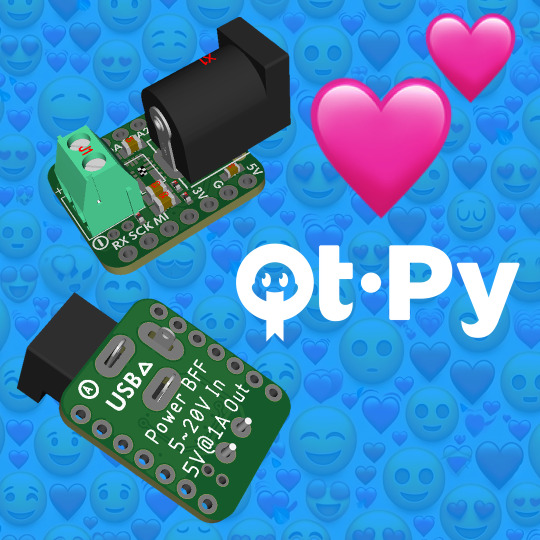
We were recently working on a project where we wanted to power a QT Py ESP32 from 12V - but the only power input on the board was USB 5V max. So here's a quick design we made to allow using these smol boards with up to 20V power! In the center is an MPM3610 integrated buck converter, which will generate 5V from up to 20V input. A 3.5mm terminal block and 2.1mm DC jack inputs are protected with an MBR120 diode. The enable and an extra ground pin are brought out to solderable pads next to the terminal block so you can use a switch to disable the converter. These can give about 1 Amp output, which should be plenty. Since it's a very bulky add-on with through-hole components, it's best to use a socket header to plug a QT Py on top rather than trying to have it solder back-to-back.
#adafruit#esp32#qtpy#bff#MPM3610#electronics#diyproject#circuitdesign#powerconverter#techinnovation#gadgetupdate#buckconverter#voltagecontrol#engineering#makercommunity
3 notes
·
View notes
Text

Loooook I got my Gherkin working! It was just a few switches, or possibly diodes, not soldered in right, not a row-pin! (which would be pretty impossible to resolve without desoldering 30 switches, on Sesame I had to desolder ONE switch and more or less destroyed the board)

Looook she's beautiful. I put spare keycaps I had lying around on her cos I am not wasting a keycap set to only use 1/3rd of it, and tbh which layer it helps most to display is actually very variable.
3 notes
·
View notes