#signal switching diode
Explore tagged Tumblr posts
Visit Tumblr Blog
Explore Tumblr blogs with no restrictions, modern design and the best experience.
Last Seen Tumblr Blogs


Fun Fact
In Q3 of 2020, 31% of US users access the Tumblr app daily.
Text
https://www.futureelectronics.com/p/semiconductors--discretes--diodes--switching/1n4148wq-7-f-diodes-incorporated-7037709
Diodes Incorporated, 1N4148WQ-7-F, Diodes, Switching Diodes
1N4148W Series 400 mW 100 V 300 mA SMT Switching Diode - SOD-123
#Diodes Incorporated#1N4148WQ-7-F#Diodes#Switching Diodes#Dual#application#radiofrequency#RF switches#ultra high speed#Pin diode switch#signal switching diode#Switching Diode#what is a switching diode#Diode switch
1 note
·
View note
Text
https://www.futureelectronics.com/p/semiconductors--discretes--diodes--small-signal-diodes/sstpad5-lf-calogic-1036092
Application of signal diode, switching circuits, types of signal diode
SSTPAD5 Series 1.5 V 10 mA Surface Mount Pico Amp Diode - SOT-23
#Calogic#SSTPAD5-LF#Diodes#Small Signal Diodes#application#switching circuits#diode small signal resistance#low voltage signals#diode voltage drop#High speed small signal diodes#PN junction diode#Schottky diode
1 note
·
View note
Text
https://www.futureelectronics.com/p/semiconductors--discretes--transistors--mosfets/dmp2165uw-7-diodes-incorporated-7129556
Mosfet vs transistor, mosfet gate, mosfet module, Mosfet switch circuit
DMP2165UW Series 20 V 2.5 A P-Channel Enhancement Mode Mosfet - SOT-323
#Diodes Incorporated#DMP2165UW-7#Transistors#Mosfets#module#Mosfet switch circuit#high voltage transistor#mosfet transistor#Types of mosfet#mosfet circuits#Small Signal MOSFET#mosfet gate
1 note
·
View note
Text
https://www.futureelectronics.com/p/semiconductors--discretes--diodes--switching/1n4148w-13-f-diodes-incorporated-9530916
Diodes Incorporated, 1N4148W-7F, Diodes, Switching Diodes
1N4148W Series 2 A 100 V 400 mW Surface Mount Fast Switching Diode - SOD-123
#Diodes Incorporated#1N4148W-7F#Diodes#Switching Diodes#applications#circuit#super fast recovery diode#RF switches#signal#Switched-mode power supplies#Microwave diode#Surface Mount Switching Diode#Diode switch
1 note
·
View note
Text
https://www.futureelectronics.com/p/semiconductors--discretes--diodes--switching/1n4148w-7-f-diodes-incorporated-4129355
Diodes Incorporated, 1N4148W-7-F, Diodes, Switching Diodes
1N4148W Series 2 A 100 V 400 mW Surface Mount Fast Switching Diode - SOD-123
#Diodes Incorporated#1N4148W-7-F#Diodes#Switching Diodes#Power supplies#chip#higher switching speed#pin diode switch#Fast#digital logic circuit#Small signal diode#High-speed switching#Small Surface-Mounted#Microwave diode
1 note
·
View note
Text
Transistor switch, Schottky diode voltage drop, Reverse Voltage Schottky
BAT54W Series 30 V 600 mA Surface Mount Schottky Barrier Diode - SOT-323
#Diodes Incorporated#BAT54CW-7-F#Diodes#Schottky Diodes#RF Diodes#Voltage Schottky Rectifier#Insulated gate bipolar transistor#chip#switch electronic signals#bipolar junction#transistor switch#voltage drop#Reverse Voltage Schottky
1 note
·
View note
Text


Leftovers & layout - WLED board revision A completed!
Sunday night, Babyada went to bed early, so we finished the capture and layout of our WLED board. Thanks to all the suggestions, we were able to implement quite a few!
For power, use USB C PD with switch-select or DC up to 24V; they are diode-OR'd together with PMEG3050
https://www.digikey.com/short/zv22b0pq
into a massive 5A 24V fuse
https://www.digikey.com/short/43qwwtwm
For the 5V regulator, we picked NCP718ASN500T1G
https://www.digikey.com/short/bb9ncc0n
- it's linear, but we don't need a lot of current at 5V. For 3.3V, we went with our trusty TPS54202
https://www.digikey.com/short/c1wnnf94
Upon request, we kept the ICS-43434 I2S microphone
https://www.digikey.com/short/28zwrrhz
and added an IR 38KHz receiver. For external connectivity, there's an ADC/DAC/GPIO #27 breakout on a JST SH 3-pin and I2C on a StemmaQT/Qwiic 4-pin.
We also added a 2x3 breakout header with 3V, GND, and 3 more GPIO so you could connect an external microphone, IR receiver, buttons, or rotary encoder. The terminal blocks have three 5V level-shifted outputs with 100 ohm in-line resistors and power/ground pairs for each. If you need just one more LED strand, the fourth 5V signal is on the 2x3 block.
Rounding out the design are four mounting holes, a reset button, GPIO #0 user button, GPIO LED, and an individual NeoPixel, which could be useful for testing. It's still pretty small, 2" x 1.3". With an ESP32-Mini module, we can pick a PCB or wFL antenna port, and it's an easy swap to make it use an ESP32-Pico, which has 2MB PSRAM.
Whatcha think - anything else we should add or watch out for?
#wled#esp32#electronics#pcbdesign#electronicsproject#makerlife#hardwarehacking#openhardware#diytech#electronicsengineering#usbc#miccontroller#neopixel#iotdevices#irreceiver#powersupplydesign#smalldesign#esp32mini#hardwarelayout#buildprogress#techinnovation
41 notes
·
View notes
Text
Why do headlights dim when a car engine is turned on?
Headlights dimming when you start the car’s engine is usually normal, but it can also signal an underlying electrical issue. Here’s why it happens and when to be concerned:
1. Normal Behavior: Momentary Dimming During Engine Startup
Cause: When you turn the key (or push the start button), the starter motor draws a massive surge of power (150–300+ amps) from the battery. This temporarily drops the battery voltage (from ~12.6V to 9–10V), reducing power to the headlights.
Duration: Dimming lasts 1–2 seconds while the engine cranks. Lights should brighten once the alternator begins charging (~14V).
Typical in: Older vehicles, cars with weaker batteries, or halogen headlights (LEDs are less affected due to lower power draw).
2. Abnormal Dimming: Persistent or Severe Voltage Drop If headlights stay dim after the engine starts or dim while driving, it indicates a problem:
Common Causes
Weak or Failing Battery: • A degraded battery can’t maintain voltage under load. • Test: Check battery voltage (engine off: <12.4V = weak; running: <13.5V = alternator issue).
Faulty Alternator: • Worn brushes, bad diodes, or a loose belt reduce charging capacity. • Symptom: Lights dim when using accessories (AC, heated seats).
Corroded or Loose Connections: • Corrosion on battery terminals, ground straps, or headlight wiring increases resistance, causing voltage drop.
Overloaded Electrical System: • Aftermarket upgrades (amplifiers, light bars) strain the alternator.
3. How to Diagnose
Test the Battery: • Use a multimeter to check voltage (engine off: 12.6V ideal; engine running: 13.5–14.5V). • Load-test the battery at an auto parts store.
Inspect the Alternator: • Rev the engine to 2,000 RPM while monitoring voltage (should stay steady at ~14V).
Check Wiring: • Clean battery terminals with baking soda/water and a wire brush. • Trace ground connections (engine block to chassis) for corrosion.
Reduce Load: • Disconnect aftermarket electronics to see if dimming stops.
4. Solutions
Replace the Battery: Opt for a higher CCA (Cold Cranking Amps) rating if you live in a cold climate.
Repair/Replace Alternator: Rebuild or upgrade to a high-output alternator if needed.
Upgrade Wiring: Replace corroded cables or install a headlight relay harness to reduce voltage drop.
Switch to LEDs: LED bulbs draw less power and are less affected by voltage fluctuations.
When to Worry
Lights stay dim even after the engine starts.
Flickering or random brightness changes while driving.
Battery warning light appears on the dashboard.
Cost Estimates Fix Cost Range Battery replacement $100–$300 Alternator repair/replace $200–$600 Wiring harness upgrade $50–$150 (DIY) LED bulb conversion $40–$200
Key Takeaway: Brief dimming during startup is normal, but persistent dimming means your electrical system needs attention. Address issues early to avoid being stranded with a dead battery! 🔧🔋

#led lights#car lights#led car light#youtube#led auto light#led headlights#led light#led headlight bulbs#ledlighting#young artist#car culture#race cars#cars#classic cars#car#suv#porsche#truck#supercar#automobile#car light#battery#engine starts#vehicle#futuristic#engineering#headlight bulb#headlamps#headlamp#headlight
4 notes
·
View notes
Text

Finally got my Eurorack system updated on ModularGrid — I hadn't gotten around to setting up a few of my custom modules, like the Harald Bluetooth Receiver, the Toy Drum, my true diode Ring Modulator, and my analog logic module "Lola".
Starting with the top left is the Behringer Radar, a contact mic and input amplifier with a gate and a triggered envelope. It's a version of the Mutable Instruments Ears (itself an adaptation of the MTM Mikrophonie); the big change is that all the sensitivity and envelope jumpers are brought out to front panel switches.
Next is one of North Coast Synthesis's "Passive Multiples and Friends", which I built as a mult.
Next is the Behringer Model 182, a clone of the Roland Model 100-series analog sequencer. (A Christmas gift from my wife's parents!)
Next is the MidCentury Modular Dividers, which combines a binary clock divider (simultaneous ÷2 - ÷128) and an adjustable (÷2 - ÷9) divider, both based on CMOS chips. (Built from a PCB/panel set).
Next is my homebrew analog logic module Lola. It has two sections: the unary input which takes one signal and outputs its inverse and its half- and full-wave rectified versions, and the binary input which gives you the OR, AND, and XOR of two signals. (Lola is named that because it's mostly based on the Mutable Instruments module "Kinks". I left off its S&H and added the XOR.)
Next is Chaos, a clone of the MI Marbles random gate and voltage generator.
Next is a set of two low-pass gates, made from vactrols, which I built onto a buggy (malformed) version of my oscilloscope module panel.
Next is my LittleBits Adapter, which lets me plug in the magnet-based circuit building toy modules including those from the Korg collab.
On the second row, we start with the Behringer Model 150, another Roland 100 series clone; this one is noise, a S&H, a ring mod (actually a chip based four quadrant multiplier), and an LFO.
Next looks like another Passive Multiples and Friends, but this one is my Simple Cascading Fixed Amplifier, a set of four fixed amplifiers set up to do x2, x10, or x20 without modifications and up to x400 with self-patching.
The next is a Passive Multiples and Friends, this one an OR Combiner meant to combine multiple gate or trigger signals.
Next is the Kassutronics VCO 3340, an analog VCO I built from the PCB/panel set — basically the CEM3340 chip broken out plus a sine wave output (though the chip is actually the AS3340 clone).
After that is the 3320-VCF by PM Foundations, a low-pass filter with voltage-controlled cutoff and resonance, again built from PCB/panel.
Then it's my first VoxMachina Sigma function/slew generator, followed by a dual attenuverter/mixer, followed by the second Sigma — all together basically a workalike of the Make Noise Maths. The Sigma is very versatile but mostly ends up used for envelopes and LFOs. I had the pcbs and panels fabricated from VoxMachina's uploaded Gerber files.
Next is another Passive Multiple.
The next is a Behringer Four Play, four VCAs that can be used separately or mixed together. It's a functional rip-off of, I believe, Intellijel's quad VCA design.
Next is my homemade ring modulator, a proper two-transformers-and-a-diode-ring unpowered design.
After that, built into another PMaF panel, are two copies of the IamO single-JFET VCA, followed by my version of David Haillant's Simple VCA.
And last in the center row is the Modular in a Week "A Simple Mixer, Right?" (ASMR). A basic five-channel mixer with plain and inverted outputs, I got this as a kit.
In the third row, we start with MiaW's POW, which has LEDs for each power rail, a USB power jack, an external Eurorack power breakout, and a switch that currently doesn't do anything. (I'm still debating whether I should add case lighting.)
Next is a very simple reverse-avalanche oscillator with (not particularly tracking) voltage control, built from LMNC schematics.
Next is the Behringer Brains, their adaptation of the MI Plaits; it's a tremendously versatile voice that's way too tempting to leave on speech synthesis mode.
After that is another Simple Cascading Fixed Amplifier. I think this one uses inverting amplifiers and the other uses non inverting ones?
Next is the Toy Drum — I tore apart one of those electronic drum kits with the roll-up rubber pads and wired up inputs to four of the triggers, giving me a cheap but cheerful kick, snare, hat, and cymbal set.
Next is the Harald Bluetooth Receiver, the module out of a DIY Bluetooth speaker; it'll play stuff off a paired phone, or read files from a microSD card or USB stick.
Next is the DSPFX, a very cheap 100-in-1 audio effects board, which I often use to add end-of-chain reverb/delay and stereo separation. Built from MiaW design, though I had the panel fabricated.
The final PMaF is wired in passive mixer mode; it usually combines the ASMR mixer's output with the stereo output from the DSPFX, the two channels feeding the Phonic, my custom headphones output device (based on the circuit from the Befaco Out).
That's a total of 6 purchased modules, 2 kit builds, 3 PCB/panel builds, 5 PMaF panel builds, 2 fabs from Gerbers, and 13 modules of assorted more custom building, all in a homemade case. Not too shabby, I guess.
2 notes
·
View notes
Text
Orange Bass Terror 1000
This amp really gave me a hard time. This amp belongs to the bass player for my band. The original issue was that the signal would cut out in the middle of practice or shows and the head would just fizzle out and shut down.

My initial thoughts were that the class D power amp was failing due to overheating. On the bench, heat seemed fine, fan kicked on with no issues and parts weren’t getting too hot, but voltages were not normal in the power supply. These amps have a smps mounted on the top of the amp.


I spent some time replacing dodgy electrolytic caps in the switching part of the power supply. Didn’t help. I flipped the amp over, voltages seemed okay for the most part but at the first power amp mosfet, there was a short between all three legs. I replaced that mosfet and the amp started to blowing fuses every time I powered it up on the variac and the fan and indicator light weren’t turning on anymore. Tracing that back through the power supply, one of the switching mosfets had failed causing the bridge rectifier, and power switching IC to fail as well. I replaced the mosfets, the IC, and the bridge rectifier.
Now we had decent voltages to most of the amp except for the -53V rail which was way off.
I started testing diodes and found that D5 in the power amp was shorted.


Of course that diode is totally inaccessible without removing the huge inductor. Once the inductor was out, the diode wasn’t reading short anymore. I was able to trace this back and the only thing that made sense was another failing power amp mosfet.

I went through and replaced the rest of the power amp mosfets and we were rocking.
Special thanks to my Rigol DS1052E on this one. Couldn’t have done it without you.
-Kaden
2 notes
·
View notes
Text
Understanding Circuit Board Electronic Components: A Comprehensive Guide
In today's digital world, electronic devices have become an essential part of our daily lives. But what makes these devices tick? At the heart of every electronic device lies a circuit board—a masterpiece of tiny electronic components working together to perform complex tasks. In this article, we’ll dive deep into the fascinating world of circuit board electronic components, exploring each element’s role and how they contribute to the overall functionality of the device.
What is a Circuit Board?
A circuit board, often referred to as a PCB (Printed Circuit Board), is a flat board used to mechanically support and electrically connect various electronic components. These components work in unison to perform a specific task. Think of the circuit board as the skeleton and nervous system of an electronic device—it holds everything together and allows communication between parts.
Types of Circuit Boards
Single-sided PCB: Has one layer of conducting material.
Double-sided PCB: Contains two layers for components and connections.
Multi-layer PCB: Complex boards with multiple layers for advanced applications.
The Role of Electronic Components on a Circuit Board
Every electronic device you interact with is powered by a carefully designed circuit board filled with various components. These components might be tiny, but each one has a critical role in the operation of the device. Here's a breakdown of the most important electronic components you’ll find on a typical circuit board.
1. Resistors
Resistors are fundamental components that control the flow of electrical current. They resist the flow of electrons, hence the name "resistor." Their primary function is to reduce current flow, adjust signal levels, and divide voltages in a circuit. Without resistors, circuits would allow too much current to flow, potentially damaging other components.
Types of Resistors
Fixed resistors: Have a set resistance value.
Variable resistors: Allow adjustment of the resistance.
2. Capacitors
Capacitors store and release electrical energy in a circuit. They are often compared to small rechargeable batteries that quickly charge and discharge. Capacitors help smooth out fluctuations in voltage, filter noise, and store energy for future use.
Common Uses of Capacitors
Energy storage
Signal filtering
Voltage stabilization
3. Inductors
Inductors are components that store energy in a magnetic field when electrical current flows through them. They resist changes in current and are typically used in circuits to filter signals, manage power, and store energy.
Applications of Inductors
Power supplies
Radio frequency circuits
Noise suppression in circuits
4. Diodes
A diode is like a one-way valve for electricity, allowing current to flow in only one direction. They are vital in circuits to prevent reverse currents, which can damage components.
Types of Diodes
Light-emitting diodes (LEDs): Produce light when current flows through.
Zener diodes: Regulate voltage within a circuit.
5. Transistors
The transistor is a versatile component used to amplify or switch electronic signals. In essence, transistors are like tiny switches that turn signals on and off rapidly, making them essential in modern electronics.
Types of Transistors
NPN transistors: Allow current flow when a small voltage is applied to the base.
PNP transistors: Conduct when the base is negatively charged.
How Circuit Board Components Work Together
In a circuit, each component has a specific role, and together they form a cohesive system. For example:
Capacitors and resistors may work together to filter signals or smooth out voltage fluctuations.
Transistors and diodes ensure that signals are amplified or directed properly.
Integrated circuits handle the complex tasks, processing data, and controlling the overall system.
Choosing the Right Components for Your Circuit Board
When designing or repairing a circuit board, choosing the correct components is crucial. Some factors to consider include:
Voltage requirements
Power consumption
Signal type and frequency
Physical size and compatibility
Conclusion
Circuit boards are an integral part of any electronic device. The various components on the board each play a specific role in ensuring the device functions as intended. Understanding these components, from resistors to integrated circuits, is essential for anyone working with electronics, whether you're designing a new system or troubleshooting an existing one.
2 notes
·
View notes
Text
ECHOBLENDER - experimental delay/distortion fog maschine

The ECHOBLENDER is based on the “Echobender” by Casper Electronics with some tweaks for improved control. A device for dark echos (low pass filtered) and the ‘blackened’ noise of the internal distortion feedback. This machine is a delay/distortion bastard. Plus it kills fascists! The controls, from upper left to lower right: DRY VOLUME, FEEDBACK(DISTORTION), WET VOLUME, COARSE TIME, FINE TIME, REPEATS. It’s a true-bypass effect with a foot-switch and a ultraviolet indicator LED and an orange clipping/limiting diode in the feedback path to make better use of the self oscillations. Instead of just a blend pot, the ECHOBLENDER has two separate VOLUME pots for a precise mix of DRY and WET signal. With the WET at zero, the DRY also works as a signal BOOSTER to increase volume of the input signal. The FEEDBACK pot let’s you play with the self-oscillation and/or distortion capabilities of this versatile effect. With the DECAY fully clockwise you get classic delay self-oscillations. Get lost in a world of foggy delay noise clouds. Build into a die-cast aluminum enclosure painted with an unique 'burned out industry camo' pattern with a METSÄÄN sticker. Power-socket: 9V DC , 2,1mm DC jack boss-style (inside -/+ outside) PSU is NOT included.Handmade by GRM for METSÄÄN. BUY HERE. (link to webshop.)


(the one directly above is already sold, before the listing. sorry.)

Some demos from previous builds (there are more on my uuutube channel):
youtube
youtube
2 notes
·
View notes
Note
Hey I just need to say absolutely adore your work here it has helped people such as me soo much on pretty much everything you need to know about their gear and I wanted to ask if I can’t spend that much money on an Marshall shredmaster what pedal can you recommend that is cheap that delivers that Marshall in a box sound as I bought an fender 85 today and I’m just stuck on what pedal to pick that is student budget friendly and can you possibly help with what amp settings jonny used in glastonbury 2003? Help would be much appreciated!
Just get a used ProCo Rat (standard version) and focus in your playing. Jonny didn't use one, but there's a reason so many people think he did: with the filter knob set right, the Rat has a similarly focused tone to the Shredmaster in the mids and highs.
The Shredmaster and Rat both use opamp hard-clipping followed by diode soft-clipping, so it's not a surprise they're similar (however, the Shredmaster has two stages of opamp clipping). The Rat lacks the post-clipping bass boost of the Shredmaster, but you can compensate for that with amp settings. Obviously, the Rat is less versatile than the Shredmaster, since it can't create scooped tones. But it does a good job of Jonny's favorite Shredmaster setting: contour knob at minimum for full mids and no scoop.
A bonus of getting a cheap, used Rat is you can quite easily modify it with a "clipping" switch, which gives access to Turbo Rat tones (the Turbo was Thom's favorite drive in the 90s, and that's probably the reason people used to think Jonny used a regular Rat). You can also get a Turbo Rat and add a switch for regular Rat tones, but the Turbo is usually pricier. Or, if you're particularly interested in soldering, you can build a mini Rat clone for about the price of a used regular Rat.

A shot of Thom about to stomp on his ProCo Turbo Rat during 2+2=5 on the Jonathan Ross show on November 7, 2003 (youtube).
Another Radiohead-related option is a Boss OD3, one of Jonny's favorite overdrives since ~2006. The OD3 has a distinctive tone of its own, but with the tone set right it has a bit of Marshall flavor too. And, like the Shredmaster, it has a post-clipping bass boost for a fuller sound. I also think it's a nice starter pedal, since it's more dynamic and "amp-like" than the Shredmaster and Rat (that's due to the OD3's discrete-opamp soft-clipping circuitry). It's quite usable from low to mid to high gain, so it could easily be your only drive pedal.
For settings, check the Fender Eighty-Five entry on Jonny's amplifiers page. But remember: even replicating his settings exactly will still sound different from studio recordings, because you're missing the signal chain after the amp's speaker (mic, EQ, compression, gates, etc). So (as always) it's better to use your ears and tweak the settings to find those sounds. We discuss this in more detail in this post.

A photo of Jonny performing with Radiohead in Kansas City in 2012 (Jason Squires). You can see his Shredmaster and his OD3 on the board on the left.
8 notes
·
View notes
Text
Working on Sophias Story again :D
-> A little later, Sophia reached maintenance shaft [xy], where the main security system of the SD of the Abyss Chrusher was located. The light activated by a motion sensor flared up in cold white with a delay of a few seconds. Neon Xilkor tubes of the NX-6 series had this somewhat unpleasant habit, which the manufacturer Asterisk never rectified. Despite this, Hallinger-FTL continued to install them in all maintenance rooms of their ship series to this day. The Davar class in particular suffered from this fact, as it had a higher number of such areas due to its modular design. As a result, Sophia had only been able to recognise the large control cabinets and component racks by the myriad of flashing LEDs when she arrived. This sea of red, orange and green diodes, which greeted her auspiciously from the steel racks, secretly watched over the entire crew and ensured that the safety units of the individual SERAHs were working.
Now that the white light flooded the room, she saw it in its entirety, and with it the technology inside. In contrast to the blinking confusion of the Sevix control racks on the right side of the room, the Servagul control cabinets on her left, unusual for a Davar-class ship, emitted a soft green glow. The reason for this was that Servagul built light panels into the doors of their products, which no self-respecting shipbuilder needed. Such nice lighting did nothing but waste power unnecessarily. Sure, ships like the Abyss Chrusher might not lack power, but that was no reason to be so wasteful.
Shrugging her shoulders, the engineer lifted her tool and the testing device before taking them to the control cabinet labelled SUR-2, where she set them down. She unlocked the door with her CAM and the handle whirred out, allowing her to open the cabinet. Sophia sighed, pulled open the cupboard door and, coloured by the light from the front panel, saw another flood of flashing or glowing diodes emanating from the security register cards. It was a sight that filled the engineer with joy, because she had hardly been able to wait to get back into the bowels of the Abyss Chrusher, but the work that was to follow was rather dull. So she plugged her headphones into her CAM, put them in her ears and switched on an album by a band Liv had shown her a few days ago. A harsh guitar riff accompanied by the vocals of a woman singing in the language of the Marlan system rang out.
She then began checking the security tabs, which initially consisted of informing the SD-SERAH of her work via the control panel in the top frame of the device. In fact, Sophia was only slightly keen on an emergency lockout of the SD, even if she could override it with her system authorisations. Basically, you had to give Servagul and Sevix credit for the cleverness of their products. After all, the automatic security system, which according to Ela - unfortunately there were no plans on this subject - summarised one subsystem of the drive per cabinet in order to pass them on to SERAH in a bundle.
You could imagine the tabs and their subsystems as the nervous system of a body, which transmitted every pain of the machines to the consciousness or to an AI. SERAH then reported the information to the Abyss Chrusher's SAM, the ship's main AI, which ensured that appropriate action was taken. What the SERAH was to the SD, the SAM was to the entire ship.
Sophia pulled a small screwdriver from the side pocket on her left arm. She used it to loosen the two neck screws on the top and bottom of the front panel of each of the seven assemblies. She was then able to pull them out by the handle to insert them into the test device. This established a serial, wired connection with the fuse register in order to then interrogate the main function of the unit on the two circuit boards of the modules. For this purpose, the test device simulated a fault by sending a specific signal sequence via the bus interface. The module processed this within a few femtoseconds and signalled an alarm back to the test device. At least that's how it worked when everything was OK. The process only took a few blinks of the eye until the technical measurement results - such as resistance, time and induction values - appeared on the display of the test device. Confirmation of the success or failure of the analysis could then also be obtained.<-
The story of the empty sky - 1 Dreams of electronic tears Chapter 10, A fairy tale of normality
#writing#booklr#books#books and reading#books and literature#writerscorner#author#books & libraries#writers on tumblr#science fiction#science fantasy#spaceship
2 notes
·
View notes
Text
Electronics Components and Uses:
Here is a list of common electronics components and their uses:
Resistor:
Use: Limits or controls the flow of electric current in a circuit.
Capacitor:
Use: Stores and releases electrical energy; used for filtering, timing, and coupling in circuits.
Inductor:
Use: Stores energy in a magnetic field when current flows through it; used in filters, transformers, and oscillators.
Diode:
Use: Allows current to flow in one direction only; used for rectification, signal demodulation, and protection.
Transistor:
Use: Amplifies and switches electronic signals; fundamental building block of electronic circuits.
Integrated Circuit (IC):
Use: Contains multiple electronic components (transistors, resistors, capacitors) on a single chip; used for various functions like amplification, processing, and control.
Resistor Network:
Use: A combination of resistors in a single package; used in applications where multiple resistors are needed.
Potentiometer:
Use: Variable resistor that can be adjusted to control voltage in a circuit; used for volume controls, dimmer switches, etc.
Varistor:
Use: Protects electronic circuits from excessive voltage by acting as a voltage-dependent resistor.
Light-Emitting Diode (LED):
Use: Emits light when current flows through it; used for indicator lights, displays, and lighting.
Photodiode:
Use: Converts light into an electric current; used in light sensors and communication systems.
Zener Diode:
Use: Acts as a voltage regulator by maintaining a constant voltage across its terminals.
Crystal Oscillator:
Use: Generates a stable and precise frequency; used in clocks, microcontrollers, and communication devices.
Transformer:
Use: Transfers electrical energy between two or more coils through electromagnetic induction; used for voltage regulation and power distribution.
Capacitive Touch Sensor:
Use: Detects touch or proximity by changes in capacitance; used in touchscreens and proximity sensing applications.
Voltage Regulator:
Use: Maintains a constant output voltage regardless of changes in input voltage or load; used for stable power supply.
Relay:
Use: Electromagnetic switch that controls the flow of current in a circuit; used for remote switching and automation.
Fuse:
Use: Protects electronic circuits by breaking the circuit when current exceeds a certain value; prevents damage from overcurrent.
Thermistor:
Use: Resistor whose resistance changes with temperature; used for temperature sensing and compensation.
Microcontroller/Microprocessor:
Use: Processes and controls electronic signals; the brain of many electronic devices and systems.
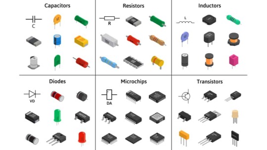
fig:google-electronics

fig:google-electronics
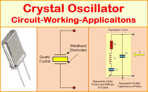
fig:Crystal-Oscillator
This list covers some of the basic electronic components, and there are many more specialized components used for specific applications within the field of electronics.
#electronic#electricity#electric vehicles#electric cars#engineering#semiconductors#wireless#cables#electronics#smartphone#hardware
4 notes
·
View notes
Text
DIY Dumble-like sounding MOSFET Overdrive

The Hermida Zendrive guitar pedal we will study, assemble and listen to today is a true masterpiece. Many say its sound is close to the Holy Grail of guitar amplification - Dumble Overdrive Special.
Other people are more pessimistic in their judgments. Still, the precise response to the picking dynamics, the Voicing tuning options, and the sheer beauty of this overdrive's sound are simply impossible not to love.
But before we study the Lovepedal Zendrive or its copy of the Landtone Phoenix song, or the Aion effects Azimuth dynamic overdrive, we'll study the evolution of the MOSFET overdrives that finally resulted in the development of this gem.
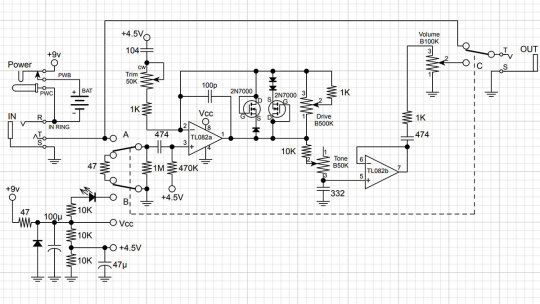
Fulltone OCD

Mike Fuller was one of the first to start using MOSFETs instead of diodes to limit the amplified guitar signal in 2004.
His Obsessive-Compulsive Drive overdrive-distortion pedal is built on a standard circuit with one dual op amp. The first operational amplifier, X1, amplifies the amplitude of the guitar signal by a factor from 8 to 463 times, depending on the position of the drive control X3. This is a 1-megohm potentiometer.

Further, through resistor R9, the signal is fed to the limiter, which comprises 2N7000 MOSFETs M1 and M2 connected in parallel. A germanium diode D1 - 1N34A is additionally included in series with M2, which makes the limiter asymmetrical and, therefore, makes more interesting sound.
A limiter in overdrives is usually included in the negative feedback circuit of an operational amplifier (i.e., in parallel with C6). Such a limiter is called a soft limiter.
And here, a hard limitation is applied: clipping sections are included between the preamplifier output of the gain section and the virtual ground - half of the supply voltage Vref, formed by resistors R4 and R7.
Virtual ground is used in the unipolar powering of operational amplifiers to amplify analog signals, such as audio signals. The guitar signal does not change from zero to plus but from minus to plus, passing through zero.
To prevent the signal from being limited to the circuit's ground, it is shifted in the plus direction by half the supply voltage.
Such hard limiting is typical for distortion pedals. But by using MOSFETs instead of diodes or LEDs, the top of the signal is not cut hard but softly rounded. Therefore, OCD can work as both distortion and overdrive.
Due to the smoothed peaks of the limited signal, the sound is highly dependent on the sound's attack dynamics. For rock and especially blues, this is very valuable. With modern metal pickups that compress the dynamic range of the signal, it can help make solos sounding more sweet.
The second operational amplifier X3 amplifies the limited signal by a factor of 3.8, correcting its timbre. Capacitors C6 and C9 prevent the self-excitation of operational amplifiers at high frequencies.
Next is a simple passive tone knob, which implies a treble leak circuit. Potentiometer X4 10 kilohms and capacitor C11 47 nanofarads are connected in the same way as on the pickguard of any electric guitar.
The Switch1 switch changes the circuit's output impedance as if the high-impedance and low-impedance pickups were switched. When it's open, you get a transparent overdrive like the Klon Centaur, and when it's closed, you can get a more aggressive sound like the Marshall Plexi.
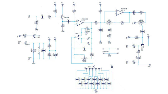
Hermida Audio Zendrive

The Zendrive pedal's authors, Hermida audio technology (now produced by LOVEPEDAL LLC), have undoubtedly studied the Fulltone OCD thoroughly. Let's find the differences between the two circuits.
First, the limiter is included in the operational amplifier feedback, that is, between the output and the inverting input, not between the output and virtual ground. That is, here we have a soft limiter.
Secondly, one diode is added in series with each MOSFET. Clipping remains asymmetric: we have one diode in the left arm of the limiter and two diodes in the right arm.
Third, the second operational amplifier is used as a voltage repeater, aka buffer: the output is directly connected to the inverting input.
Fourth, the tone control is implemented a little differently: two OCD`s switchable resistors are replaced by a potentiometer.
And finally, the most critical, fifth difference. A potentiometer is included in the tone correction circuit between the inverting input of the first operational amplifier and the artificial midpoint.
This fourth knob, Voicing, or Character, allows you to smoothly adjust the lower frequencies in the overdrive structure over a wide range, similar to the Resonance control on many tube guitar amps.
The potentiometer is signed as a trimmer in the diagram because some pedal makers don't want to install a fourth knob on the pedal`s body. This is what Landtone did when developing the Phoenix Song Overdrive DIY kit.
The developer suggests installing the trimmer on the PCB, and to access it, you need to disassemble the pedal by unscrewing the footswitch nut and taking out the PCB.
But I will not be lazy to drill an extra hole in the pedal body and install a potentiometer with a knob, connected to PCB by wires instead of the trimmer. Because I consider this regulator simply invaluable and irreplaceable.

Before we get to assembly and testing, let's look at another pedal with a similar adjustment. However, it is based not on the Fulltone OCD but on the Ibanez Tube Screamer.
The Precision Drive

This is a signature pedal by Misha Mansour of Periphery, manufactured by Horizon Devices. Compared to the original Overdrive Pro TS808, the circuit adds a noise suppressor, which we will not consider, and an exciting ATTACK switch.
The Precision Drive scheme was studied and partially replicated by PedalPCB and PCB Guitar Mania. They are manufacturers of DIY kits for guitarists. Their products are called Dwarven Hammer and Collision Drive, respectively. A noise gate is not provided there, but the attack switch is implemented. This is the main difference between Precision Drive and many other overdrive pedals.
In the Fulltone OCD schematic, we saw a resistor switch at the tone shaping circuit in the output section. The Zendrive has a variable resistor in the preamp's RC circuit which is controlling the overdrive structure.
Precision Drive has a constant resistor in the same place, between the inverting input of the overdrive section operational amplifier and the virtual ground, but the capacitors are switched.
This is the same thing: we change the time constant of the RC circuit, which adjusts the audio signal's frequency spectrum. At the same time as the time constant, the complex impedance changes, thus the gain.
A resistor is a resistance to both DC and AC current. At the same time, a capacitor is only resistant to AC current because DC current does not flow through a capacitor. Since DC current does not flow through our RC circuit, there is no difference between adjusting the resistance and switching the capacitance.
But the active/reactive ratio affects the circuit's Quality factor, i.e., its resonance. It's no coincidence that the knob on guitar amplifiers, which adjusts the same frequencies as our potentiometer or switch, is often called RESONANCE. And it is used to adjust to the resonance of the electromechanical system - the loudspeakers in the cabinet, along with the masses of air in and around it.
The reactive impedance accumulates energy and gives it away, except for losses due to dielectric recharging and magnetizing the magnetic core in inductors. This is why coreless inductors are often used in high-end equipment, so-called air inductors. They weigh a lot, take up a lot of space, and are expensive because copper is more expensive than steel. But these are the laws of physics on which technology is based.
Unlike reactive impedance, active resistance converts electrical energy into heat, thus reducing the Q-factor. In some cases, it is necessary and useful. In others, it is harmful. Or it simply creates a unique sound character.
That's why switching capacitors and turning the potentiometer knob in the feedback circuit of an audio frequency amplifier is almost the same thing, but not quite. And it's great that there are such different variants of guitar overdrive pedals!
Landtone Phoenix Song Overdrive
Now you can hear how my Zendrive from the Landtone OD-1 kit sounds, with a Seymour-Duncan SH4 humbucker on a Gibson MM Explorer guitar, into an Orange MT20 with a Torpedo Captor X. And see how I assembled the pedal and also a kitten walking around the table and prancing around.
youtube
I liked the pedal, especially its fourth magic Voicing knob, which does things to the sound that other tone controls can't. I also liked the bird on the body. Because I love birds. And in the music world, the decoration of instruments and hardware plays no small role because it inspires creativity. And the fact that the pedal is assembled by my hands also warms my soul and creates inspiration.
3 notes
·
View notes