#Under Voltage Relay
Text
Buy Under Voltage, Over Voltage, Start-Stop, Photocell, Liquid Level Relays in Dubai, UAE
Discover a wide range of high-quality relays in Dubai, UAE. Shop under voltage relays, over-voltage relays, start-stop relays, photocell relays.Order now for fast delivery!
#Phase Failure Relays#Over Voltage Relay#Photocell Relay#Under Voltage Relay#Under Current Relay#Phase Protection Relay
0 notes
Text
Ship Current Monitoring Relay (over/ under current monitoring relay on ship electrical system)
Ship overcurrent relays are used to protect sensitive equipment against over or under current conditions. By using current transformers (CTs), these protective relays monitor large AC currents common to large motor starters, circuit breakers, and transformers.
Ship current transformers CT which steps down the monitored current to a secondary (output) range of 0 to 5 amps (AC) to power the…
View On WordPress
#current monitor relay#current monitor relay on ship#current transformer#inder voltage relay#over current relay#ship monitor relay#ship over current relay#ship under current relay#under current relay
5 notes
·
View notes
Text
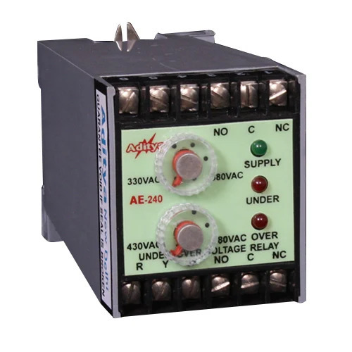
Under Voltage Relay Manufacturers
Aditya India is one of the best Under Voltage Relay Manufacturers and suppliers in India. Our company is well-known for producing Under Voltage Relay, which are used to prevent damage from transient blackouts and brownouts to gensets, pumps, motors, shunt caps, transformers, and other electrical equipment. They are also used for auto start-stop functions on AMF panels, where a changeover signal is generated by a low or high in any phase. For more details, Visit the website.
Address -RZ -445/15, Tughlakabad Extension, Tughlakabad, New Delhi, Delhi 110019
Contact US - 08061859680
0 notes
Text
Failsafe software has been installed to Spamgon without issue.
The failsafe software creates pop-up messages when a piece of code is run on Spamgon. These will pop-up under three circumstances; action override, biological override, or pain override. For example, if someone were to hit Spamgon (please do not), the pain override failsafe would not activate. He would feel pain as normal. Failsafes can only be triggered by running code directly on Spamgon. There are workarounds, and it is not perfect. But for the purpose of double checking each and every function I personally run on him, this will work.
The process of testing the failsafe was tedious. For each type of override, I ran a small piece of code that should trigger a pop-up. I had Spamgon relay the pop-up to me, then deny it. This then repeated, but instead he accepted it. For the action override, his spun slowly for a few seconds, and the pop-up would read for him as "functional override, rotation of head segment, 5 rpm, proceed?". For the biological override, his left arm segment would turn green for a few seconds, displaying the pop-up "biological override, recolor left arm segment, hex value #3d8c40, duration 3 seconds, proceed?" For the pain override, a small shock would be delivered to his right arm segment, displaying the pop-up "pain override, shock to right arm segment, 5 kV, proceed?" We also repeated with a faster rpm, a different hex value, and a lower voltage to ensure the readings on the pop-up were correct.
The failsafe appears successful, however I will be staying here overnight and asking that he stays in the lab as well, in case there are any issues.
I do... feel bad about testing the pain override. The shocks were at such a low voltage that it should be no more than a carpet shock from static electricity, but it made him jump. Spamgon appeared uncomfortable when I asked him to select "yes" for the pop-up. In the long term, I know this is important. If there is ever more significant pain caused by running code, we know the failsafe will trigger and stop it before it happens. I still can not help but feel terrible. Watching him jump at the sudden shock, it felt cruel. Maybe there was a way to save him the pain. Maybe I should have tried harder.
He is putting his trust into me, and I am fearful it may all come crashing down. I hope this works. For his sake, I will do everything I can.
@ask-spamton-gpory-spamgon
9 notes
·
View notes
Text
Advancing Reliability: Sudharsan Insulations Safety Innovations
In the realm of electrical safety, the significance of robust protective measures cannot be overstated. As industries continue to evolve, so do the risks associated with electrical systems. At Sudharsan Insulations, we take pride in pioneering cutting-edge solutions to mitigate these risks effectively. Our comprehensive range of products caters to diverse needs, ensuring utmost safety and reliability in electrical operations. Among our flagship offerings are the ELCB, Primary Current Injection Test Kit, and Extra High Voltage Test Kit (EHV Test Kit), each designed to address specific challenges and bolster safety standards in various applications.
ELCB: Elevating Safety with Enhanced Protection
The term "ELCB" stands for Earth Leakage Circuit Breaker, a vital component in electrical installations. This device serves as a proactive safeguard against electric shock by automatically disconnecting the circuit upon detecting an imbalance in the electrical currents. Sudharsan Insulations' ELCBs are engineered with precision and adhere to stringent quality standards, making them indispensable in residential, commercial, and industrial settings alike.
Understanding the Functionality of ELCB
ELCBs operate on the principle of differential current measurement. The device continuously monitors the live and neutral currents in the circuit. Under normal conditions, the sum of these currents is zero. However, if a leakage occurs, the imbalance triggers the ELCB to trip, thereby disconnecting the circuit and preventing any potential harm. This rapid response is crucial in environments where electrical safety is paramount.
Applications of ELCB
Residential Buildings: ELCBs protect inhabitants from electrical hazards, especially in wet areas like bathrooms and kitchens where the risk of electrical shocks is higher. They are essential in modern homes, providing an added layer of safety for families.
Industrial Plants: In industrial settings, ELCBs safeguard machinery and personnel from the risks of electrical faults and leakages. They are crucial in environments with heavy electrical equipment, ensuring operational safety and continuity.
Construction Sites: ELCBs are vital in construction sites where electrical installations are prone to damage and mishandling. They ensure safety during the construction phase, protecting workers from potential electrical hazards.
Benefits of ELCB
Enhanced Safety: ELCBs provide instantaneous detection and interruption of electrical faults, preventing potential hazards and significantly reducing the risk of electrocution and fires. This makes them an essential component in any electrical safety protocol.
Operational Reliability: ELCBs offer reliable performance, ensuring the uninterrupted operation of electrical systems. This reliability minimizes downtime and maintenance costs, contributing to overall operational efficiency.
Compliance Assurance: ELCBs from Sudharsan Insulations adhere to international safety standards and regulations. This compliance fosters trust and confidence among stakeholders, assuring them of the highest levels of safety and quality.
Primary Current Injection Test Kit: Empowering Precision Testing
The Primary Current Injection Test Kit is an indispensable tool for evaluating the performance and integrity of protective relay systems in electrical networks. It simulates fault conditions by injecting a precisely controlled current into the primary circuit, enabling accurate testing and calibration of protective devices. Sudharsan Insulations' Primary Current Injection Test Kits are renowned for their accuracy, reliability, and user-friendly interface, making them a preferred choice among discerning professionals.
Understanding the Functionality of Primary Current Injection Test Kit
The Primary Current Injection Test Kit operates by injecting a high primary current into the circuit. This current simulates real fault conditions, allowing for the testing and calibration of various protective devices such as relays, circuit breakers, and transformers. The kit ensures that these devices will respond correctly during actual fault conditions, thereby safeguarding the electrical network.
Applications of Primary Current Injection Test Kit
Power Distribution Networks: The Primary Current Injection Test Kit is crucial in verifying the responsiveness of protective relays to fault conditions, ensuring optimal performance and grid stability. It is essential for maintaining the integrity and reliability of power distribution systems.
Industrial Installations: In industrial settings, the Primary Current Injection Test Kit is used for testing and commissioning protective relay systems in substations, motors, and transformers. This testing prevents equipment damage and production downtime, ensuring seamless operations.
Electrical Maintenance: The Primary Current Injection Test Kit is invaluable in conducting periodic assessments of relay settings and functionality. Regular testing ensures that protective devices are always ready to operate in case of faults, upholding safety standards and regulatory compliance.
Benefits of Primary Current Injection Test Kit
Precision Testing: The Primary Current Injection Test Kit provides accurate simulation of fault conditions, enabling thorough testing and validation of protective relay systems. This ensures optimal performance under diverse scenarios, enhancing the reliability of electrical networks.
Time and Cost Efficiency: The streamlined testing procedures of the Primary Current Injection Test Kit minimize downtime and operational disruptions. This efficiency maximizes productivity and cost savings, making it a cost-effective solution for testing and maintenance.
Versatile Applications: The Primary Current Injection Test Kit is compatible with a wide range of protective relay systems and configurations. This versatility enhances flexibility and usability across diverse electrical installations, making it a valuable tool for various applications.
Extra High Voltage Test Kit (EHV Test Kit): Redefining Safety Standards
In the realm of high-voltage electrical systems, uncompromising safety measures are paramount. The Extra High Voltage Test Kit, designed for testing insulation integrity and dielectric strength in high-voltage equipment, plays a pivotal role in ensuring operational reliability and personnel safety. Sudharsan Insulations' EHV Test Kits are engineered to deliver precise and consistent results, offering unparalleled performance in critical applications.
Understanding the Functionality of Extra High Voltage Test Kit
The Extra High Voltage Test Kit operates by applying a high voltage to the equipment under test, assessing its insulation integrity and dielectric strength. This testing identifies any weaknesses or defects in the insulation, allowing for corrective measures before catastrophic failures occur. The EHV Test Kit is essential for maintaining the reliability and safety of high-voltage equipment.
Applications of Extra High Voltage Test Kit
Power Transmission Networks: The Extra High Voltage Test Kit is used to assess the insulation integrity of transformers, cables, and switchgear components. This testing prevents catastrophic failures and blackouts, ensuring the stability and reliability of power transmission networks.
Renewable Energy Projects: In renewable energy projects, the Extra High Voltage Test Kit is used to test insulation systems in wind turbines, solar inverters, and HVDC installations. This testing maximizes energy efficiency and reliability, supporting the growth of sustainable energy solutions.
Research and Development: The Extra High Voltage Test Kit is invaluable in research and development settings. It is used to conduct laboratory tests on insulation materials and high-voltage equipment, advancing technological innovations and safety standards.
Benefits of Extra High Voltage Test Kit
Superior Performance: The Extra High Voltage Test Kit offers high-precision testing capabilities, ensuring accurate evaluation of insulation integrity. This precision minimizes the risk of electrical breakdowns and outages, enhancing the reliability of high-voltage equipment.
Enhanced Safety: The early detection of insulation defects and weaknesses by the Extra High Voltage Test Kit mitigates the risk of electrical hazards. This testing safeguards personnel and assets against catastrophic failures, promoting a safe working environment.
Regulatory Compliance: The Extra High Voltage Test Kit from Sudharsan Insulations adheres to international standards and industry regulations. This compliance demonstrates a commitment to safety and quality excellence, fostering trust and credibility among stakeholders.
Conclusion
At Sudharsan Insulations, our commitment to innovation and excellence drives us to continually raise the bar in electrical safety solutions. With our comprehensive range of products and unwavering dedication to quality, we empower industries to operate with confidence in the face of evolving challenges. Whether it's safeguarding residential premises, optimizing industrial processes, or advancing technological frontiers, Sudharsan Insulations is your trusted partner in ensuring a safer and more reliable electrical future.
By integrating advanced technology and adhering to rigorous safety standards, Sudharsan Insulations is dedicated to providing solutions that not only meet but exceed the expectations of our clients. Our products, including the ELCB, Primary Current Injection Test Kit, and Extra High Voltage Test Kit, are designed to address the unique challenges of various electrical environments, ensuring safety, reliability, and operational efficiency.
In today's rapidly evolving electrical landscape, the importance of robust safety measures cannot be overstated. With Sudharsan Insulations' innovative solutions, you can be assured of superior protection and performance, paving the way for a safer and more efficient future. Let us partner with you in elevating electrical safety to new heights.
Explore here to know more about :
Earth Leakage Circuit Breakers (ELCB) Importance of Electrical Safety
#Elcb#Best Elcb#Primary Current Injection Test Kit#Best Primary Current Injection Test Kit#Extra High Voltage Test Kit#Best Extra High Voltage Test Kit
0 notes
Text
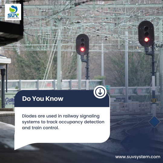
Railway signaling systems are integral to the safe and efficient operation of rail networks. Among the many #components that contribute to the functionality of these systems, #diodes play a crucial role, particularly in track occupancy detection and train control mechanisms. @suvsystemlimited , a #leadingsupplier of high-quality #electroniccomponents, is proud to support the #railwayindustry with a comprehensive range of reliable diodes.
Diodes in Track Occupancy Detection
When a train enters a track section, the wheels and axles create a short circuit, which is detected by the diodes. This information is then relayed to the signaling system to manage train movements and prevent collisions.
SUV System Ltd offers a variety of diodes that are ideal for use in track occupancy detection systems. Our diodes are known for their precision, reliability, and durability, ensuring accurate detection and long-term performance.
Diodes in Train Control Systems
In addition to track occupancy detection, diodes are essential components in train control systems. These systems regulate train speeds, manage traffic flow, and ensure adherence to schedules. Diodes are used in signal circuits to control the flow of current and protect against voltage spikes and surges.
SUV System Ltd provides products that are designed to handle high current loads and operate efficiently under varying environmental conditions, making them suitable for the demanding applications in the railway industry.
For more information on our range of diodes and how they can enhance your railway signaling systems, visit our website or contact our sales team. We are committed to providing high-quality components that meet your specific needs and ensure the reliable operation of your railway systems.
Feel free to contact us at [email protected] or connect on Skype at [email protected]
You can also visit us at https://www.suvsystem.com/
#semiconductors#electronic components#diode supplier#diodes#electronics supplier#diode#tvs diode#railway system
0 notes
Text
Overvoltage and Under Voltage Relay (59/27) Test
This article is to guide the responsible persons in conducting Overvoltage and Under Voltage Relay (59/27) Test procedure. Testing overvoltage (59) and undervoltage (27) relays ensures the protection of electrical equipment from voltage deviations beyond acceptable limits.
Test Equipment: Secondary Injection test kits; Multimeter; Digital Timer
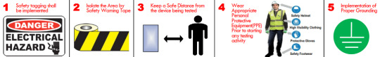
Safety Precautions: The following Safety…
View On WordPress
0 notes
Text
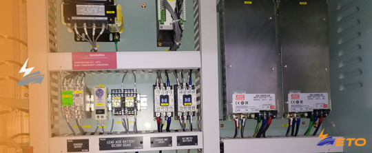
The major component of Switchgear installation

In the realm of electrical power distribution, switchgear plays a pivotal role in ensuring the safe and efficient management of electricity flow. AEPL Company, a renowned name in the power industry, specializes in the installation of cutting-edge switchgear systems. In this article, we will explore the essential steps involved in the installation of switchgear, shedding light on AEPL’s expertise in providing reliable and robust power solutions.
Crucial components of AEPL company’s switchgear installation
Comprehensive Site Assessment
The process begins with a thorough site assessment conducted by AEPL’s team of skilled engineers. They meticulously evaluate the existing electrical infrastructure, taking into account factors such as load requirements, voltage levels, and safety regulations. This initial analysis enables AEPL to design a switchgear system that seamlessly integrates with the client’s specific needs and optimizes electrical distribution.
Design and Engineering
Once the site assessment is complete, AEPL’s team of experienced engineers collaborates to design a tailor-made switchgear solution. They carefully select the appropriate switchgear components, including circuit breakers, transformers, relays, and control panels, to meet the client’s unique requirements. AEPL emphasizes factors such as reliability, safety, and energy efficiency while designing the switchgear system.
Procurement and Quality Assurance
AEPL prioritizes the procurement of high-quality components from trusted manufacturers to ensure the durability and performance of the switchgear system. The company maintains strong partnerships with reputed suppliers, guaranteeing that all components meet industry standards and regulations. Rigorous quality checks are carried out to ensure that the procured components align with AEPL’s stringent quality benchmarks.
Installation and Integration
The installation phase marks a critical milestone in the switchgear installation process. AEPL’s team of skilled technicians and engineers work diligently to install and connect the switchgear components. Ensuring precision and adherence to safety protocols, they carefully wire the circuit breakers, transformers, and control panels, meticulously integrating them into the existing electrical infrastructure.
Testing and Commissioning
Once the installation is complete, AEPL conducts a series of comprehensive tests and system checks to verify the functionality and performance of the switchgear system. Load tests, insulation tests, and protection relay tests are performed to ensure the system operates seamlessly under varying electrical conditions. AEPL’s team meticulously fine-tunes the system parameters and settings to optimize its performance and reliability.
Training and Handover
AEPL believes in empowering its clients with the knowledge necessary to operate and maintain the switchgear system effectively. After successful commissioning, AEPL provides comprehensive training to the client’s personnel on the operation, maintenance, and safety protocols of the switchgear. This equips the end-users with the skills to handle routine operations, monitor the system, and respond promptly to any potential issues.
Conclusion
AEPL Company’s expertise in switchgear installation exemplifies their commitment to delivering safe, reliable, and efficient power solutions. Through meticulous site assessment, design, procurement, installation, testing, and training, AEPL ensures that the switchgear system seamlessly integrates into the client’s electrical infrastructure. With AEPL’s cutting-edge solutions, businesses can embrace a robust power distribution network, enabling them to operate smoothly and safeguarding their operations from electrical disruptions.
#electrical work#architectural design and construction#facilities services#fabrication and structures work#civil construction work#electrical turnkey projects#architectural work#interior design#lighting solutions#transformer installation
0 notes
Text
Why India Is the Biggest Market For Stabilizers?
India is commonly mocked for its erratic power supply, and fluctuating voltage. It is projected that such fluctuations suffer a yearly loss of INR 12 crore to Indian families, in the form of obsolete home appliances. Though India has gained traction in the ground of electricity development, with huge power generating plants being built, and rural areas being inflated with high-voltage power cables; voltage fluctuation remains a restrain in the development of India.
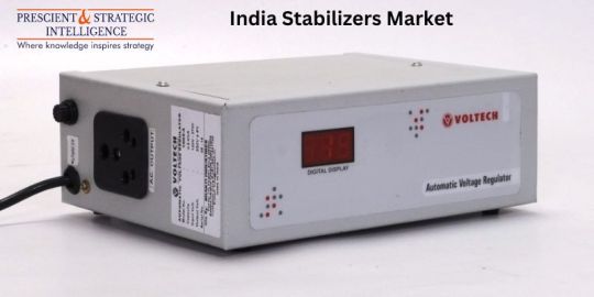
Before moving further, let us first know what exactly is a voltage stabilizer.
It is an electrical appliance that is created to provide a constant voltage to a load at its output terminals regardless of the fluctuations in the input or incoming supply voltage. It defends the equipment or machine against over-voltage, under-voltage, and other voltage flows.
FIXED OR ADJUSTABLE
Voltage stabilizers are offered with adjustable or fixed output voltage. If you don’t require to slender the output voltage or adjust it to a non-standard voltage then the fixed voltage regulator will utilize fewer parts and thus makes for a more practical choice.
What is a single-phase stabilizer?
single phase voltage stabilizers offer better rapidity time against voltage fluctuations and disparity of power consumed by a load. Series SNA comprises a line conditioner transformer with a steady output voltage and attenuation and filtering of electromagnetic disturbances.
Why do we need stabilizers?
Stabilizers are essential to guard electric home appliances from voltage variations and their significance. Fluctuations may be low or high that is high voltage or low voltage and both are damaging to the working of appliances. Abrupt High voltage supply can cause everlasting damage to appliances and insulation damage to windings.
The low voltage supply is also unfitted for electric appliances as it causes issues in the appliances and computational faults that decrease the speed and performance of appliances. The safety of electric appliances from damaging consequences of voltage fluctuations is the factor for the presence of voltage stabilizers.
Kinds of voltage stabilizers
Several voltage stabilizers work as voltage modification but voltage stabilizers are primarily of 3 types- physically operated or switchable voltage stabilizers, constant voltage correction stabilizers, and stabilizers armed with power electronic control circuits:
Relay-type voltage stabilizers
Servo-controlled voltage stabilizers
Static Voltage Stabilizers
Mainline Stabilizers
If you use any electric appliance on low voltage like lights fans and any other electrical devices, it decreases the performance and lifespan of the equipment. mainline stabilizers are made to shield the whole house from a continuous low-voltage supply and offer continual mains power.
Hence, India is a developing country with the world second highest population, and power Fluctuation is a big problem in India, as the purchasing power of common people is increasing, the power consumption will also going to increase as people going to buy more electrical appliances, which will eventually increase the need for stabilizers to cope up with Fluctuation issues.
Source: P&S Intelligence
#India Stabilizers Market Share#India Stabilizers Market Size#India Stabilizers Market Growth#India Stabilizers Market Applications#India Stabilizers Market Trends
1 note
·
View note
Text
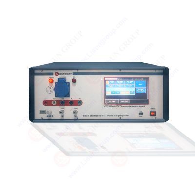
Exploring the Effects of EFT Immunity Measurement and Testing on Human Health
I. Introduction
EFT Immunity Measurement is an interference simulation generator for electronic products and is an instrument for the quick transient burst pulse anti-interference test, as well as a kind of electromagnetic compatibility anti-interference test instrument, which is used to testthe resistance of electronic and electrical systems to quick transient interference. This quick transient burst pulse group generator includes power supply system, keyboard unit, display unit, main control unit, high voltage power supply, energy storage capacitor, main capacitor, frequency generating circuit, main switch, waveform circuit and coupling-decoupling circuit. The main control unit controls the high voltage power supply to charge the energy storage capacitor and the energy storage capacitor charges the main capacitor through the charging circuit.
The main control unit generates the corresponding control signal according to the preset frequency to control the opening and closing of the main switch. When the main switch is opened, the main capacitor is discharged through the waveform circuit to form the fast transient/burst interference waveform, and the main control unit controls the coupling-decouplingcircuit to couple the interference to the equipment under test (ETU) power supply according to the set channel, or It outputs the interference waveform according to the source output mode. This coupling-decoupling circuit adopts a digital control system, which is easy to operate, has good human-computer interface, shortest coupling path and good waveform consistency. When the main switch is off, the energy storage capacitor is charged to the main capacitor. The frequency generating circuit is used to generate PWM signals to control the main switch. When the switch is switched at different frequencies under the control of different frequency PWM (Pulse Width Modulation) signals generated by the main control unit frequency generating circuit, different frequency quick transient waveforms are generated. Parameters of this generator are input by the keyboard unit and parameter display is completed by the display unit. The power supply system adopts 220V, 50HZ AC power and converts multiple DC power supplies for the generator through the power interface and switch power supply.
II. Features
A EFT Immunity Measurement, characterized in that it comprises a power supply system, a keyboard unit, a display unit, a main control unit, a high voltage power supply, an energy storage capacitor, a main capacitor, a frequency generating circuit, a main switch, a waveform circuit and a coupling-decoupling circuit, wherein the main control unit controls the high voltage power supply to reach the set voltage and charges the energy storage capacitor, the energy storage capacitor charges the main capacitor through the charging circuit, and the main control unit generates the corresponding control signal according to the preset frequency to control the opening and closing of the main switch When the main switch is opened, the main capacitor forms an interference waveform through the waveform circuit, when the main switch is turned off, the energy storage capacitor is charged to the main capacitor, the frequency generating circuit is used to generate the PWM signal to control the main switch, and When the switch is switched under the control of different frequency PWM signals generated by the main control unitfrequency generating different frequency quick transient waveforms are generated.
III. Purpose of EFT Test
The purpose of the quick transient burst pulse EFT test is to verify the anti-interference ability of mechanical switches caused by inductive load switching, relay contact bouncing, high voltage switch switching and other instantaneous disturbances. This test method is a pulse group test composed of many quick transient pulses coupled to
the power line, control line and signal line. Easy problems occur in power equipment or monitoring power grid equipment, equipment used in industrial automation, medical monitoring and other detection of weak signal equipment.
Lisun Instruments Limited was found by LISUN GROUP in 2003. LISUN quality system has been strictly certified by ISO9001:2015. As a CIE Membership, LISUN products are designed based on CIE, IEC and other international or national standards. All products passed CE certificate and authenticated by the third party lab.
Our main products are Goniophotometer, Integrating Sphere, Spectroradiometer, Surge Generator, ESD Simulator Guns, EMI Receiver, EMC Test Equipment, Electrical Safety Tester, Environmental Chamber, Temperature Chamber, Climate Chamber, Thermal Chamber, Salt Spray Test, Dust Test Chamber, Waterproof Test, RoHS Test (EDXRF), Glow Wire Test and Needle Flame Test.
Please feel free to contact us if you need any support.
Tech Dep: [email protected], Cell/WhatsApp:+8615317907381
Sales Dep: [email protected], Cell/WhatsApp:+8618117273997
Read the full article
0 notes
Text
Toonami Weekly Recap 03/16/2024
Ninja Kamui EP#06: The organization begins searching the city for the lieutenant and Higan. After retreating to heal Higan, the lieutenant reveals herself to be Emma, otherwise known as Aska. She explains to Higan that she was sent by the clan in order to spy on him under the guise of a rookie FBI agent. Aska informs Higan that it will be virtually impossible to defeat the organization without using an armored suit and informs him that she has taken one of the most advanced models during their escape, the Kamui. To use it, Higan must be directly synched to the suit via neural pathways for it to function. Before putting him into deep sleep for the procedure, Aska confirms she was the one who saved him back during the ambush and helped him infiltrate the city. Lil manages to locate their hideout and Aska engages him in battle before ultimately being defeated. During the synching, Aska subconsciously relays to Higan that she was only able to save him because she didn't arrive in time. She explains that Mari saved her life long ago and that the two of them stayed in touch since. Higan finishes the synching and confronts Lil in the Kamui.
Lycoris Recoil EP#09 - What's done is done: Takina manages to force Himegawa to flee, but she still applied a high voltage discharge into Chisato's heart, making it unable to be recharged, giving Chisato only two more months to live. This devastates Takina, but Chisato returns to her daily life, unfazed. Kusunoki recruits Chisato for a raid on Majima's hideout, but she only agrees if she reinstates Takina. Kurumi has Mika reveal ten years ago, despite her talent, Chisato suffered from a congenital heart disease that only gave her six months to live. Seeing her potential, Yoshimatsu arranged for Chisato to receive an artificial heart, under the condition Mika raised her like their own daughter, and ensured she used her talent for killing. However, Chisato saw Yoshimatsu as her "savior", and thus used her abilities for good. Takina and Mizuki overhear the story, and they all agree the best way of tracking down Yoshimatsu is through Majima. Meanwhile, Majima learns about Yoshimatsu and comes up with a new plan. Takina decides to return to the DA to help Chisato, and arranges for a day off to spend time with her. After visiting the park, she thanks Takina and gives her her scarf as a present before leaving. Meanwhile, Yoshimatsu and Himegawa are ambushed and captured by Majima.
Demon Slayer: Kimetsu no Yaiba: Entertainment District Arc EP#17 (44) - Never Give Up: Tanjiro survives his fall but is confronted by Gyutaro, who mocks his inability to protect Nezuko and his friends, slamming him around the burning city. He offers to transform him but Tanjiro responds by head-butting him, secretly stabbing him with a poisoned kunai. With Gyutaro immobilized, he attempts his Hinokami Kagura once more to behead him. Daki intervenes but is attacked by Zenitsu, reaching her neck with his fastest form. Gyutaro removes the kunai and recovers. Before he can kill Tanjiro, Tengen, having halted the poison's effects, intervenes, battling Gyutaro despite his wounds. Seeing his chance, Tanjiro reaches Gyutaro's neck but is stabbed in the jaw. His scar transforms into a fiery mark, giving him the strength to slice through. Zenitsu loses momentum without cutting Daki's neck but is joined by Inosuke, revealing he moved his internal organs upon getting stabbed, causing Gyutaro to miss his heart. The Demon Slayers simultaneously behead the siblings, but in the aftermath, Gyutaro’s body suddenly erupts with blood blades, destroying the city.
#Toonami#Toonami Weekly Recap#Mexico vacation 2024#mexico vacation#Ninja Kamui#Lycoris Recoil#Demon Slayer: Kimetsu No Yaiba#Demon Slayer 2#Entertainment District Arc
0 notes
Text
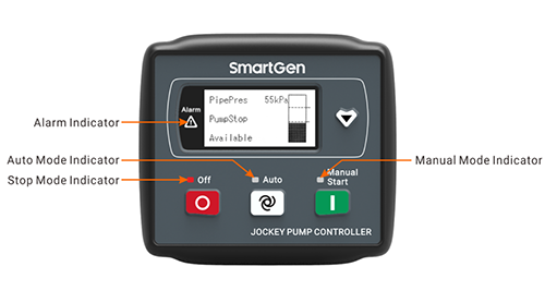

SmartGen | FPC1700 Jockey Pump Controller will launch
FPC1700 Jockey Pump Controller is composed of a microprocessor as the core, which can be started/stopped according to the pipe pressure, stabilize the pipe pressure in the setting range and detect the grid voltage to protect the abnormal voltage, realizing the automation and intelligent control of the controller. It integrates LCD display and with good HMI function.
Characteristics and Performance
1P2W, 3P3W and 3P4W system types are configurable;
The LCD is 128x64 pixels with backlight, optional Chinese and English;
With MCU smart accurate monitoring and control;
With OFF/Auto/Manual modes;
With over/under voltage, over/under frequency and reverse phase detection functions, over/under voltage and frequency threshold values are available to set;
The cut-in/cut-off pressure threshold values can be set;
The pipe pressure sensor can be configured to resistance/current/voltage types, and can customize the sensor curves;
LCD can visually display the current pipe pressure, total running time, pump start times, AC power status and alarm status;
All the output ports are relay output;
Working temperature range is (-25℃~+70℃), which can be used in the bad environments;
Rubber seal designed between the enclosure and controller with protection level IP65;
Modular design, anti-flaming ABS enclosure, pluggable terminals and built-in mounting with compact structure and easy installation.
FPC1700 Front Panel
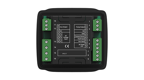
FPC1700 Back Panel
Specification Parameters
Please contact business managers of SmartGen for more details, looking forward to your choice!
SmartGen, making control smarter!
www.smartgen.cn
0 notes
Text
The Ultimate Guide On How To Reset Coolant Temp Sensor: Step-by-Step Solutions
Understanding the Coolant Temperature Sensor
The coolant temperature sensor (CTS), also known as the engine coolant temperature sensor, plays a crucial role in a vehicle's engine operating system. It is typically a thermistor, with resistance that varies based on temperature. The sensor's probe is immersed in the engine coolant, allowing it to measure temperature fluctuations and convert them into voltage signals for the engine control module (ECM).
Location and Function
The CTS is commonly located near the thermostat, on the engine block, cylinder head, or intake manifold. Its primary function is to measure the temperature of the engine coolant and relay this data to the ECM. Armed with this information, the ECM can optimize various operations like activating cooling fans, adjusting fuel injection and ignition timing, and managing variable valve timing – all to ensure peak performance, efficiency, and prevent overheating.
Types of Coolant Temperature Sensors
- Thermistors: Most common type that changes resistance based on temperature for precise ECM readings.
- Resistance Temperature Detectors (RTDs): More accurate but costlier, uses materials like platinum.
- Thermocouples: Ideal for extreme temperatures, generates voltage based on temperature differences.
- Bi-metallic strips: Less accurate, uses differing metal expansion rates but rarely used in modern vehicles.
Symptoms of a Bad Coolant Temperature Sensor
- Overheating engine
- Poor fuel economy
- Check engine light illumination
- Black smoke from exhaust
- Engine misfires
- Erratic temperature gauge readings
- Rough engine running
- Engine stalling or hesitation
Diagnosing CTS Issues
Testing with a Multimeter:
1. Locate and disconnect the CTS electrical connector
2. Set multimeter to ohms to measure resistance
3. Check resistance value against specifications in the service manual for that temperature range
4. Results outside the specified range indicate a faulty sensor
Visual Inspection Without Multimeter:
- Check for physical damage or cracks
- Inspect electrical connections for corrosion/dirt
- Look for coolant leaks around the sensor
- Monitor temperature gauge behavior during warmup
- Note any performance issues like poor fuel economy or stalling
Causes of Coolant Temperature Sensor Failure
- Electrical problems or damaged wiring
- Physical damage from impact or vibrations
- Contamination buildup
- General wear and tear over time
- Excessive overheating
- Improper installation
- Exposure to corrosive coolant additives
- Rare manufacturing defects
How To Reset Coolant Temp Sensor
Method 1: Clearing Fault Codes with an OBD-II Scanner
1. Locate the OBD-II diagnostic port (under dash)
2. Connect scanner with ignition on, engine off
3. Scan for any fault codes related to the CTS
4. Follow prompts to clear codes from the computer
5. Disconnect scanner
Method 2: Temporarily Disconnecting the Sensor
1. Ensure engine is off and cooled down
2. Locate and disconnect the CTS electrical connector
3. Wait a few minutes to clear residual data
4. Reconnect the CTS
5. Start engine and monitor temperature gauge
Selecting the proper reset method depends on the vehicle's make/model and whether fault code clearing is required.
Repairing vs. Replacing the Sensor
In most cases, a failed coolant temperature sensor cannot be repaired due to its delicate internal components. Repair attempts risk further damage, so replacement is the recommended solution when the sensor fails. Professional diagnosis is advisable to pinpoint the problem accurately.
When to Replace
There is no set replacement interval, but most coolant temperature sensors last around 100,000 miles. However, this can vary by vehicle, driving conditions, etc. Replace if experiencing symptoms of sensor failure like check engine lights, overheating, or rough running.
Replacement Process
1. Locate the coolant temperature sensor
2. Disconnect the electrical connector
3. Remove the old sensor
4. Install the new, compatible replacement sensor
5. Reconnect electrical connector
6. Refill cooling system with fresh coolant
7. Start engine and check for leaks
In summary, the coolant temperature sensor is vital for managing engine temperature and enabling proper ECM operation for peak performance and efficiency. Recognizing the signs of failure, performing basic diagnosis, and knowing when replacement is required can prevent costlier repairs down the line. Following the proper resetting and replacement procedures is key to restoring optimal cooling system function.
0 notes
Text
LV switchgear commissioning | Switchgear commissioning
LV (Low Voltage) switchgear commissioning is a critical process that involves the verification and testing of various components to ensure proper functionality and compliance with safety standards. While I don't have specific content from Bin Ghalib Engineering, I can provide you with a general overview of LV switchgear commissioning.
LV Switchgear Commissioning Process:
Inspection:
Visually inspect the switchgear for any physical damage, loose connections, or irregularities.
Ensure that the installation complies with manufacturer specifications and industry standards.
Documentation Review:
Check all relevant documentation, including drawings, manuals, and test reports.
Functional Testing:
Verify the proper functioning of individual components such as circuit breakers, contactors, relays, and meters.
Confirm that all control and monitoring systems are operational.
Electrical Testing:
Conduct insulation resistance tests to ensure there are no electrical leakages.
Perform continuity tests to validate the integrity of electrical connections.
Protection Relay Testing:
Test protective relays to ensure they operate correctly in response to fault conditions.
Secondary Injection Testing:
Simulate fault conditions through secondary injection testing to verify the response of protection relays.
Control System Testing:
Test the control system to ensure accurate transmission and reception of commands.
Load Testing:
Apply loads to the switchgear to assess its performance under normal operating conditions.
Commissioning Report:
Prepare a comprehensive report detailing all tests conducted, results, and any issues identified.
Include recommendations for corrective actions if needed.
Training:
Provide training to end-users or maintenance personnel on the operation and maintenance of the switchgear.
Safety Checks:
Ensure that safety features such as interlocks and emergency shutdown mechanisms are functioning correctly.
As-Built Documentation: Update documentation to reflect any modifications made during the commissioning process.
0 notes
Text
Efficient Overcurrent Control: Exploring Siemens 7SJ80 Siprotec Compact Relay Features
In the ever-evolving landscape of electrical power systems, the need for robust and efficient overcurrent protection has become paramount. Siemens, a pioneer in advanced industrial solutions, has introduced the 7SJ80 Siprotec Compact Relay, a cutting-edge device designed to revolutionize overcurrent control. This blog aims to delve into the distinctive features of the Siemens 7SJ80, unraveling its capabilities and highlighting the ways it enhances the reliability and safety of electrical networks.
The Siemens 7SJ80 Siprotec Compact Relay stands out as a versatile and intelligent solution, offering a myriad of features tailored to address the challenges associated with overcurrent conditions. As we navigate through the blog, we will explore the relay's state-of-the-art functionalities, from its precise fault detection mechanisms to its adaptive protection settings. This exploration will provide an in-depth understanding of how the Siemens 7SJ80 empowers engineers and operators to optimize overcurrent control strategies, ensuring a seamless and efficient operation of power systems. Join us on this journey as we unlock the potential of the Siemens 7SJ80 Siprotec Compact Relay and discover how it contributes to the next generation of smart and reliable electrical protection.
Introduction to Siemens 7SJ80 Siprotec Compact Relay as a Cutting-edge Solution
Within the realm of cutting-edge solutions, the Siemens 7SJ80 Siprotec Compact Relay takes center stage as a pioneering device. This section introduces the Siemens 7SJ80 relay, highlighting its advanced features and capabilities. As a trusted name in industrial solutions, Siemens brings innovation to the forefront with this compact relay, offering a promising solution to the challenges posed by overcurrent conditions.
The Siemens 7SJ80 Overcurrent Protection relay stands out as a versatile and multi-functional solution tailored for motor protection. Specifically designed for asynchronous motors of all sizes, the SIPROTEC 7SJ80 serves as an ideal choice. It not only encompasses essential functions for motor protection but is also equipped to function as a reliable backup relay for transformer differential protection. The compact design of the Siemens SIPROTEC 7SJ80 enhances its adaptability, making it a flexible choice for various applications.
What sets the Siemens SIPROTEC Compact 7SJ80 apart is its flexibility in protection functions. Users have the capability to create up to 20 additional protection functions, allowing for a highly customizable and adaptable protection scheme. This feature empowers users to implement specific protections, such as change for frequency or reverse power protection. The 7SJ80 relay goes beyond mere protection; it facilitates circuit-breaker control, controls other switching devices, and supports automation functions. With an integrated programmable logic (CFC), users can even add their own functions, enabling automation of switchgear through interlocking. Furthermore, the user has the freedom to generate personalized, user-defined messages, adding another layer of customization to the relay's capabilities. The Siemens SIPROTEC 7SJ80 relay, with its extensive features and user-friendly design, emerges as a comprehensive solution for efficient and adaptable motor protection.
Protection Functions Of Siemens 7SJ80 Relay
Directional time-overcurrent protection (67, 67N)
Negative-sequence protection (46)
Under-/overvoltage protection (27/59)
frequency protection (81O/U)
Sensitive dir. ground-fault detection (67Ns)
Undercurrent monitoring (37)
Overload protection (49)
High-impedance restricted ground fault (87N)
Overcurrent protection (50, 50N, 51, 51N)
Breaker failure protection (50BF)
Siemens 7SJ80 Overcurrent Protection Hardware
Pluggable current and voltage terminals
5/8 binary outputs (2 changeover/Form C contacts)
4 current transformers
0/3 voltage transformers
3/7 binary inputs (thresholds configurable using software)
1 life contact
Conformal coating available (NEW)
Key Features
Newly introduced conformal coating for enhanced protection
Convenient pluggable current and voltage terminals
Settable binary input thresholds with three stages using DIGSI
Adjustable secondary current transformer values (1 A / 5 A) via DIGSI
Equipped with nine programmable function keys
Easily replaceable buffer battery accessible from the front
Two additional communication ports for increased connectivity
Integrated switch supporting low-cost and redundant optical Ethernet rings
Ethernet redundancy protocols (RSTP, PRP, and HSR) ensuring optimal reliability
Relay-to-relay communication through Ethernet with IEC 61850 GOOSE
Millisecond-accurate time synchronization via Ethernet with SNTP
Connect up to two SICAM I/O units to expand the number of binary inputs and outputs.
COMMUNICATION INTERFACES
System/service interface
– IEC 61850 Edition 1 and 2
– IEC 60870-5-103 and IEC 60870-5-104
– PROFIBUS-DP
– DNP 3.0
– MODBUS RTU
– DNP3 TCP
– PROFINET
– Ethernet redundancy protocols RSTP, PRP and HSR
Ethernet interface for DIGSI 4 and extension up to two SICAM I/O-Units 7XV5673
USB front interface for DIGSI 4
Conclusion:
In conclusion, the Siemens 7SJ80 Siprotec Compact Relay emerges as a game-changer in the realm of overcurrent control, providing a comprehensive and sophisticated solution for the challenges faced by modern electrical power systems. Throughout this exploration, we've witnessed how the relay's advanced features, such as its adaptive protection settings, precise fault detection mechanisms, and versatile functionality, contribute to a more resilient and efficient operation. The 7SJ80 not only enhances the reliability of power systems but also empowers engineers with the tools needed to tailor protection strategies to specific network requirements.
As we wrap up our journey into the Siemens 7SJ80, it's evident that the relay is not merely a component but a strategic asset for any facility seeking optimal overcurrent control. Its compact design and intelligent capabilities pave the way for a future where electrical networks can operate seamlessly, adapting to dynamic conditions while ensuring the safety and longevity of critical assets. The Siemens 7SJ80 Siprotec Compact Relay marks a significant leap forward in the evolution of overcurrent protection, setting a new standard for efficiency, adaptability, and reliability in the ever-evolving landscape of electrical engineering.
For the most competitive pricing on the Siemens 7SJ80 Siprotec Compact Overcurrent Protection Numerical Relay, connect with Reliserv Solution – your authorized supplier and channel partner for Siemens Numerical Relays, Automation Products, Power Quality Meters & Instruments, MV Switchgear Spares, and PSS SINCAL Software. As a prominent supplier and exporter of Siemens Siprotec Compact products based in Mumbai, Maharashtra, Reliserv Solution offers an extensive array of services and tailored solutions for industries and panel builders. Reach out to us at +917506112097 or email us at [email protected] with your specific requirements. We specialize in a comprehensive range of Siemens Relay products, and to explore our Siemens Numerical relays collection further, click here.
#panelbuilders#siproteccompact#Siemens#powersystems#7SJ80#overcurrentprotection#relay#smartgrids#industrialautomation#powerquality#numericalrelays#electricalengineering#automationsolutions#energyefficiency#electricalsafety#digitaltransformation#customizedsolutions
0 notes
Text
Keep Yourself Protected With LEC’s Grounding Rod
Grounding protection is referred to as protective earthing. It is an essential technical measure taken to prevent personal electric shock and ensure the regular operation of electrical equipment.
The basic principle of grounding rod and protection is to limit the leakage current of the leakage device to the ground so that it does not exceed a specific safety range. Once the protection device exceeds a particular set value, the power supply can be automatically cut off.
The grounding protection has the following advantages:
It limits the voltage that will be applied to the equipment insulation.
Recall that the materials used in the insulation have to be able to withstand the applied voltage.
Limits system voltage to ground or equipment enclosures under normal and fault conditions, increasing personnel safety.
Minimizes potential transient overvoltages.
Provides for a source of ground-fault current relaying, allowing fast fault clearing.
Transient overvoltages are daily events in electric power systems. Switching is their main initiator, but switching surges are relatively easy to handle. However, lightning surges are the most severe and challenging to manage. They may increase the system voltage to many times the rated voltage. If the equipment in the power system is not protected against lightning surges, considerable damage will occur.
LEC’s lightning protection system diverts lightning and provides a specific path for conducting the surges safely to the ground by adequate down conductors to grounding rod. Thus, it helps prevent disastrous events like fires, injuries, and deaths.

Their patented Chem-Rod Grounding Electrode is the latest electrode used worldwide. It provides a low surge impedance as well as low resistance earth contact. The ground augmentation fill is the key component that makes this Chem-Rod maintenance-free, giving a longer performance and ensuring the best grounding connection possible. It has a large conductive surface but takes up far less land mass and can easily replace ten conventional grounding rods.
In conclusion, grounding is essential in preventing electrical faults from becoming dangerous by providing a safe pathway for electric currents to travel without risking human life or property damage. Keep yourself protected adequately with grounded equipment today.
Get in touch with us today.
Our Smart Ground Testing services are engineered to offer reliable, very practical solutions to improve the grounding system, and its audits are highly accurate. Don't wait until an accident happens before taking action.
Read more...
#Lightning Damage#Lightning Protection#Lightning Protection Design#Lightning Protection Products#Lightning Protection Systems#Lightning Rod Protection#Lightning Surge Protection Devices#Fuel Tank Lightning Protection#Grounding Rod#Tank Battery Lightning Protection
0 notes
Last Seen Blogs

sentiped
Senty

somedscontent
K1ªriņcjů§z

corpseofyesteryear
Monochrome

an-idiot-that-likes-emo-mus-blog
MCR trash

dancingprincessblog
BE A BETTER VERSION OF YOURSELF