#Wearable Electronics
Text
Scientists from NTU Singapore have developed ultra-thin semiconductor fibers that can be woven into fabrics, turning them into smart wearable electronics. Their work has been published in the journal Nature.
To create reliably functioning semiconductor fibers, they must be flexible and without defects for stable signal transmission. However, existing manufacturing methods cause stress and instability, leading to cracks and deformities in the semiconductor cores, negatively impacting their performance and limiting their development.
Continue Reading.
95 notes
·
View notes
Link
#nanotechnology#smartmaterials#robotics#scienceandtechnology#electronics#wearable electronics#plastics#futurism#materialsscience
40 notes
·
View notes
Text

0 notes
Text

Harvesting human motion energy: The promise of wearable triboelectric nanogenerators
There is a lot of mechanical energy in human activities, but human activities are low frequency and irregular. As such, traditional electromagnetic power generation mode cannot efficiently collect this energy without affecting the normal activities of the human body.
A new energy harvesting method, called triboelectric nanogenerator (TENG), can efficiently collect low-frequency and irregular mechanical energy such as mechanical vibration, sound waves, raindrops, and so on. But there's a catch: Achieving the flexibility, stretchability, and wearability of the TENG is a prerequisite for harvesting energy from the human body. Therefore, the scientists' mission is to make the TENG wearable.
Current methods for achieving TENG flexibility and stretchability mostly rely on the properties of the material itself.
Read more.
29 notes
·
View notes
Text
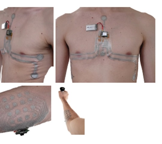
Electronics 'Tattoos'
Electronics ‘Tattoos’
Source images: Carnegie Mellon University
Electronic “tattoos” using thin-film electronic patches would be used for monitoring healthcare in future in terms of better signal quality, higher patient comfort and wearability. Applications include Electrocardiography (heart monitoring), electroencephalography (brain activity monitoring), electrooculography (eye movement monitoring) or…
View On WordPress
#disease diagnosis#E-Skin#electronics#futuristic smart technology#health care#tattoos#wearable technology
3 notes
·
View notes
Text
Spuncksides Promotion Production - Home Goods Store in Battle Creek
THE ONLINE MARKETING CONNECTION
Savvy shoppers shop online!
We recognize our SFI (Strong Future International) eCommerce Merchant Associates and will reserve this space for those Merchants to share with our audience the products and services offered by these entrepreneurs.
2 notes
·
View notes
Text
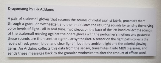

Seeing these on the museum's wall made it all feel so real. Then seeing our display in the window from the sidewalk and getting compliments from random passerby suddenly made it so worth all the struggles to get here. ❤🧡💛💚💙💜💖


#museum display#wearable synth#experimental tech#electronic music#dragonsong#our work#center for new music#window gallery
4 notes
·
View notes
Text
Embracing the Digital Revolution in Healthcare

In today's fast-paced world, the healthcare industry is experiencing a profound transformation, driven by the rapid advancement of technology. As we move forward, it's crucial for healthcare professionals and organizations to embrace technology fully to enhance patient care, improve outcomes, and streamline processes.
One of the most significant advancements in recent years is the rise of telemedicine. With telemedicine, patients can connect with healthcare providers remotely, breaking down barriers of distance and increasing accessibility to quality care. This innovative approach not only saves time and resources but also enables individuals to receive timely medical attention, especially in underserved areas.
Furthermore, HealthTech innovations are revolutionizing how healthcare is delivered and managed. From AI-powered diagnostics to virtual reality therapy, these cutting-edge technologies are reshaping the landscape of medicine, offering new possibilities for diagnosis, treatment, and monitoring of patients' health.
Digital health solutions play a pivotal role in modern healthcare systems, facilitating seamless communication and collaboration among healthcare professionals and empowering patients to take charge of their health. Mobile apps, wearable devices, and remote monitoring tools are just a few examples of how digital technologies are transforming healthcare delivery and empowering individuals to lead healthier lives.

Speaking of wearable health devices, they are becoming increasingly popular among consumers, allowing them to track various health metrics such as heart rate, sleep patterns, and activity levels in real-time. These devices not only promote proactive healthcare management but also enable healthcare providers to gather valuable data for personalized treatment plans.
Moreover, the adoption of electronic health records (EHR) has revolutionized medical documentation, replacing traditional paper-based systems with digital platforms that enable secure storage, easy retrieval, and efficient sharing of patient information. EHR systems not only improve accuracy and efficiency in healthcare delivery but also enhance patient safety and enable better coordination of care among multidisciplinary teams.
In conclusion, the digital revolution in healthcare is not just about embracing technology; it's about leveraging its full potential to transform the way we deliver and experience healthcare. By embracing telemedicine, HealthTech innovations, digital health solutions, wearable health devices, and electronic health records (EHR), we can create a more efficient, accessible, and patient-centered healthcare system for all. Let's embrace the future of healthcare today!
#Telemedicine#HealthTech Innovations#Digital Health Solutions#Wearable Health Devices#Electronic Health Records (EHR)
0 notes
Text

Wearable devices might be used in clinical trials for collecting real-time information, which promotes patient engagement. Although there are certain potential challenges around this integration, these device development companies suggest effective solutions to overcome these problems. In all, it can be said that ‘the future of integration of wearable devices with EHR is quite bright’!
#Wearable Integration#Wearable App Development#Mobile App Development#Electronic Health Records#Wearable Health Technology#mHealth Apps
0 notes
Text
Discover the Latest Electronics Gadgets for Every Need
Discover a world of innovation with our collection of electronics gadgets. From cutting-edge smartphones to stylish watches and captivating home decor, explore a range of tech-forward products designed to elevate your lifestyle.
#Electronics#Gadgets#Tech#Innovation#Consumer Electronics#Smart Devices#Wearable Technology#Electronic Accessories#Cutting-edge Gadgets#Digital Devices
0 notes
Text

0 notes
Link
3 notes
·
View notes
Text
The Technocolour Dreamcoat 3.0 beta
After ten years of faithful service, the Technocolour Dreamcoat 2.0 finally kicked the bucket. The silicone potting over the LED strips hardens over time and when the strip bends, the hardened silicone grips the LED chips and lifts them off the copper substrate. I replaced one glitchy strip and then identified the same problem in the neighbouring one, at which point I worked out was going on and realised it was futile.
So it was time to think about a redesign. This was great, as I’d get to incorporate a bunch of the ideas I’d had and new technology that had been released over the previous decade.
What needed improvement?
It turns out the silicone-potted strips have a lifespan. What’s new in the last few years are “pearl” LED strings which contain (I assume) 2020 WS2812 LEDs potted in little blobs of milky resin. These strings are much more flexible than strips and so will at least have a different failure mode (and I hope they’re significantly longer-lived.) They’re also light—important for a wearable!—and come in an interesting variety of pitches.
Another technology that didn’t exist a decade ago is the PixelBlaze. Don’t get me wrong, FastLED on a Teensy served me very well, but I’m not a huge fan of the “C++ in nose glasses” and “IDE that took a decade after the Retina MacBook Pro to catch on to Retina font rendering” aspects of the Arduino environment.
PixelBlaze also has a very interesting approach to LED mapping: patterns draw to a 0.0 to 1.0 line (or grid, or volume) of floats and the software re-maps that back out to the physical grid of pixels for your particular build. This means it natively supports non-regular pixel maps of arbitrary size from the same pattern code. It also supports 1-, 2- and 3D mappings, including cute arrangements like polar coordinates, which is useful for a piece like a jacket that’s essentially a cylinder. I thought that was worth trying for the trade of its “JavaScript in nose glasses” environment. More thoughts on how this tradeoff went later.
Finally, power. I was peaking at about 4A delivered by two USB batteries. But that is way, way less than what the LEDs themselves can take. I wanted the next version to be able to deliver all the power the LEDs could possibly consume at max brightness.
What worked well?
I briefly flirted with the idea of a new structure but after tearing the electronics off the jacket and washing it (for the first time in… um, let’s not say) I realised that was silly. The original jacket I’d commissioned from the fetish wear shop in Amsterdam[1] was too good a starting point to give up.
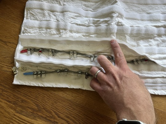
Another thing that really did hold up from the first design was the power bus. I’d had my fetish fashion designer friend run a couple of flaps right around the bottom of jacket, closed with Velcro. Through each of those I ran a length of braided copper ground strap with spade connector tabs bolted onto it (the positive bus is split in two, one half for each battery; the ground goes right around.) Wires soldered onto the LED strip’s positive and negative pads had spade connectors crimped on and connected to the appropriate power bus. This gave me a low resistance power bus and basically no voltage drop between the “first” and “last” strips.
Finally, I also liked having physical controls; namely a next/previous pattern button and a brightness pot. The PixelBlaze has a built-in web server for control, but “Wait a minute, I need to connect to my jacket’s wifi” is not something I ever wanted to have to say on the Playa.
The Design Process
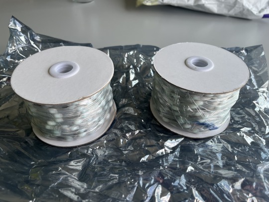
I ordered 1m of 50mm pitch pearl LED string to prototype with. After playing around with them and some graph paper, I decided 25mm pitch would be perfect if I offset them in alternating rows. This gives me equilateral triangles of not quite exactly 20mm per side (but close enough for government work) and a non-rectilinear arrangement which I find quite pleasing, plus a high, but workable density. Back-of-envelope calculations with the area of the jacket gets me to about 1400 pixels total with this arrangement.
Next problem was how to attach them to the jacket. The theory about Velcroing the strips to the jacket bottom layer so they could be removed for cleaning was sound, but in practice removing 32 individual strips (and unplugging their connectors) was so laborious I never did it. Plus, the pearl strings don’t really lend themselves to having Velcro attached to them. The docs for the strings (such as they are) recommend injecting power every 100-120 pixels or so and at my chosen density that’s four rows up and down the jacket from hem to collar. So I needed “panelise” the strings in lots of four columns somehow.
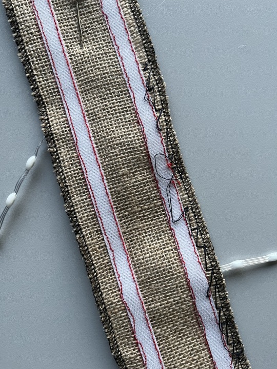
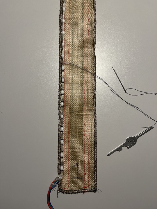
I could do this on strips of fabric with Velcro sewn to their backs, which I’d then sew the strings on the front of. For attaching the strings I initially shied away from sewing (because it’s not a skill I had heretofore developed) and tried using small zip ties. This didn’t work out well; it was as slow and laborious as sewing would have been and got you a bunch of sharp edges for your trouble (where you cut the tails of the ties off.) I chose hessian (burlap) as the substrate material, originally because I thought it would be easier to get the zip ties through, but it turns out it’s also amenable to sewing with a darning needle and stout thread. Another advantage is that it has a built-in “grid” that helps me keep my strings of LEDs straight and set my offsets correctly spaced.
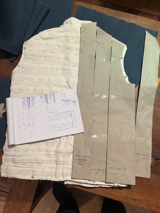
The build
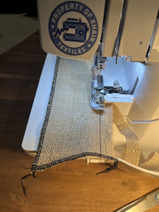
First I drew up paper patterns for all the panels; unsurprisingly one half of the jacket is a mirror image of the other so I only had to make six. Using these as templates I drew the panel outlines on the hessian then cut them out coarsely. I have access to an overlocker at my hackerspace, so I used this to hem the panels and trim them to size at the same time. Thank you to whoever had threaded and set the tension on the overlocker before I used it, it was pretty straightforward after testing out how it worked on some scraps first.
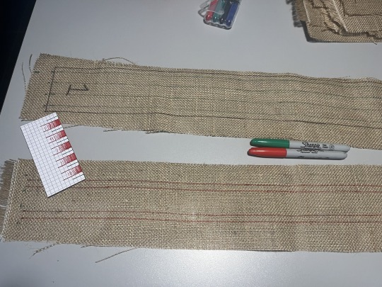
I arranged and numbered the panels flat out on the table, being double-triple careful to ensure I had everything the right way up given half of them were mirror images of the other half. Then I outlined two things: lines on the “top” of the panel, correctly-spaced for the rows of LEDs; and on the bottom two sets of “lanes” for the Velcro to be sewn in between. I had to experiment on paper first to get the spacing right as, given you can’t hand-sew through the Velcro, the LED lines and Velcro “lanes” had to be separated properly.
Next up was sewing the Velcro. This was a horrible job, considering that I’d forgotten absolutely everything I knew about using a sewing machine in the two decades or so since I’d last done it. Winding a bobbin, threading the goddamned thing, setting thread tension—I did all of these the hardest possible ways out of pure ignorance. Sewing Velcro isn’t easy either, but made less so by the Velcro I’d bought having hooks edge-to-edge with no “hem” to sew on up each side.
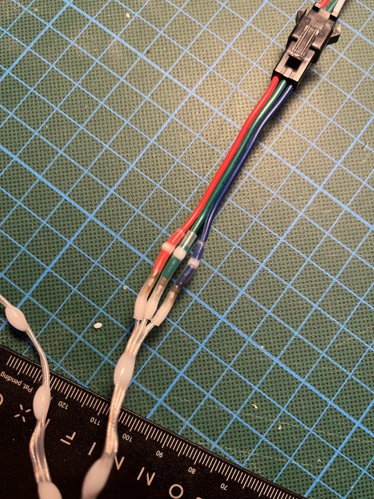
But with a lot of swearing I finally worked it all out and got it done. Next came attaching connectors to the LED string. I had a bunch of 3 pin JST connectors left over from a previous build but soldering them on would have been a massive pain. So I learned about the latest thing in butt connectors: solderless butt connectors! I ordered the smallest ones I could from Amazon and they turned out to be the perfect size to connect the tiny wires on the strings (32AWG?) to the much bulkier (~24AWG) tails on the JST connectors.
I soldered the female JST onto the start of the string, then sewed it onto the hessian from the reel until I got half way down the last row, at which point I’d know what my last LED would be so I could cut the string then solder on the other JST connector. Then sew down the rest of the row. The sewing is the tedious part and took the most time and swearing. You have two choices: tie on a short length of thread and have to tie it off and the new one back on quite frequently, or use a much longer thread and have it tangle on everything from the Velcro on the backs of the panels to the buttons on your shorts as you’re sewing. In the end I went with the longer thread and being careful[2], but I still don’t have a reliable knot for tying the start and end of the thread off on the hessian. Suggestions please.
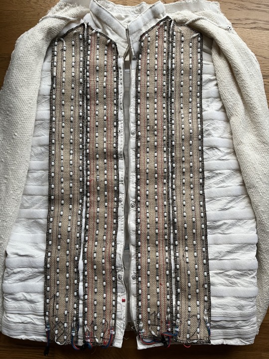
The important (and deliberate) part about this design with the panels was that I could complete the whole piece in stages. As long as I had done at least two panels and stuck them either side of the zipper at the front, the piece would be presentable and I could test it in public. Indeed its first public appearance was in that form and I took it to Burning Man with only four panels finished.
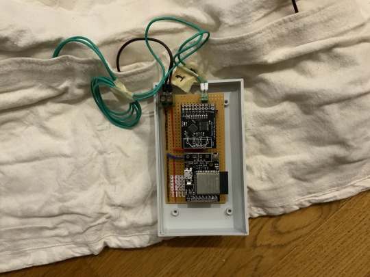
Then, there’s the control hardware and software. Available alongside the PixelBlaze controller itself is the output expander. It uses a serial protocol connection to the PixelBlaze controller and can output frames to each of the 8 connected strings simultaneously, greatly increasing your effective frame rate for 3-wire LEDs. My plan was to knock up a quick protoboard harness for the controller and expansion board and socket them in but that didn’t quite work out. The PixelBlaze pins aren’t breadboard-compatible and in addition, despite being the same sizes, the controller and expansion board’s power and RX/TX pins don’t line up. I’ve got to admit I found this kinda odd and it will make it more difficult than it needs to be when I ultimately have to design a proper PCB to mount them on alongside the power components.
But with some socket headers soldered at OCD-triggering angles I got it to basically fit together. Add some header terminals for power and signal and then it’s a Simple Matter Of Programming.
Actually before programming, there’s “mapping”. As I mentioned earlier, the PB software has a really interesting approach where patterns are programmed against an 0.0 to 1.0 line/area/volume and that’s mapped back out automatically to your actual pixel grid—which you have to specify. This can be done programmatically or by uploading a photo of your piece into a web tool and clicking on each LED, in order. This is tedious for 400-odd LEDs, but do-able.
You then take the mapping file (a JSON array of 2D points in my case) and upload it to the web interface the PixelBlaze serves. Its configuration pages can then show you previews of the various patterns that come preloaded with the system as they would look on your project. There’s a “playlist editor” where you can select which patterns will play in what sequence and with what delay, and you can edit the pattern code directly.
That is, you must edit the patten code directly. The editor is built into the interface the PixelBlaze serves over http. You can’t really create and preview a pattern on a computer then upload it to the PixelBlaze—you have to create and edit patterns on the PixelBlaze, which means you can’t effectively keep them under source control. I realise the target user might not be someone who is aware of the existence of git, but as someone who does software for a job it’s a bit of a drawback.
Next the control box. I soldered a couple of buttons and a potentiometer onto a little protoboard along with some pull-up resistors and designed a 3D printable case for it in ShapeScript (thanks to Nick for helping me out with how to do beveled edges!) Then I went to check out the APIs for changing patterns in PixelBlaze and they didn’t exist. There was only one way to change the pattern, and that was to press the button that was soldered onto the PixelBlaze board—or pull the pin it was connected to down to ground. Fortunately, Wizard was able to quickly add an API for me that allowed me to do what I wanted; I wired my buttons to some GPIO pins and everything worked great[3]!
And that’s the state it was in when it came with me to Burning Man. Unfortunately, I got one wear out of it before it started glitching out. From previous experience (it took a couple of outings to get the previous version to be reliable) I’ve determined that attempting to debug this kind of thing on-Playa is futile and not much fun, so I wore other pieces. At home I worked out that poking it in a particular place on the power bus would make it glitch but I couldn’t figure out why so I stripped the panels and power bus off and re-connected everything. It was better, but still not perfect, and for now I’m side-eyeing the power connection to the control box. Given the next phase requires a complete rebuild of that, I’m not too worried.
There are several more things to do before I’m going to count the hardware as “finished”: the most obvious is the grind of sewing and wiring the remaining eight panels. Once that’s done, I will work on…
MOAR POWER
I said earlier my goal was to be able to supply as much power as the final ~1400 LEDs would take. I know this is ridiculous but christ it’ll be cool[4]. I estimate it will draw in the region of 200W, which I plan to deliver from a couple of macho remote control car batteries bucked down to 5V via two 20A Murata OKL/T-20-W12 non-isolated DC-DC converters. I’ve had a good experience with the little siblings of these Murata parts before on another project and you just can’t get 100W out of USB battery banks—even USB-C PD ones generally top out at less than that, and even if you found one that did you’d be losing a significant amount of charge going from the internal cell voltage up to 20V then back down to 5V. However I seriously do not recommend anyone else attempt this. It’s a ridiculous idea, it’s not particularly safe, and 3A @ 5V is part of the USB-C PD spec which, times two (with a split positive rail[5]), is way more than enough to be obnoxiously bright in any situation. It’s entirely a stunt. But if I can pull it off you’ll be able to see me from space.
While we’re talking about power I wanted to note another quirk of PixelBlaze I wasn’t expecting: FastLED has a really neat feature where it will dynamically, every frame, scale the brightness of the output down to fit inside your specified power limit. It’s an estimate based on the type of LEDs you use so it’s not exact but it’s very very handy, especially for wearables. If you know your batteries can only deliver X amount of current, you can ensure your patterns are as bright as they could be without going over that. This is something which is apparently not possible due to some aspect of the design of the internals of PixelBlaze.
Anyway, to do all this I’ll need to design a custom circuit board to mount the PixelBlaze, the Output Expander, the sensor board, two Murata DC-DC converters (with edge-plated castellations), a power bus capable of delivering 20A, fuses in case it can’t and some kind of enclosure for all the above that won’t melt or set me alight. And KiCad and I don’t get along.
So that’s the state of the project right now! Hopefully I’ll see you—or more likely, you’ll see me—at Burning Man 2024.
[1] Walking past one day I saw a heavy canvas strait jacket in the window. Absent the arms and with the addition of Velcro strips sewn laterally around, it was perfect.
[2] Neutralising the hook Velcro by closing it with a strip of the loop Velcro helped, but I still ended up getting tangled at the ends of it.
[3] I added a little bit of debounce logic in software and it’s not 100% reliable, but good enough. Maybe I just need to tweak the constants, or maybe debounce is better done in hardware.
[4] I know, I know, it will be the absolute opposite of cool—even maxing out at 4A the old one got pretty warm to wear.
[5] This is very important; people warned me but my first design, where I linked the outputs of multiple USB battery packs together, fried four of them before I listened.
0 notes
Text
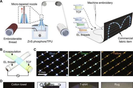
Light-emitting textiles for diverse flexible and wearable displays
Textile research has highlighted the advances in electroluminescent threads as suitable biomaterials for driving growth in the wearable electronics market. While the direct embroidery of textiles with custom designs and patterns can offer substantial benefits, machine embroidery can challenge the integrity of these threads.
In a new report of applied science and engineering published in Science Advances, Seungse Cho and a team of scientists in biomedical engineering and medicine in the U.S., present embroiderable, multicolor, electroluminescent threads in blue, green, and yellow, that show compatibility with standard embroidery methods.
The researchers used the threads to stitch decorative designs onto a variety of consumer fabrics, without compromising their wearability or light-emitting capacity. The scientists illuminated specific messages or designs on the consumer products for the purpose of developing emergency alerts on helmet liners and as physical hazard signs.
Read more.
15 notes
·
View notes
Text
Embracing the dynamic realm of technology, wearable electronics emerge as the forefront of electronic innovation. The landscape is being reshaped by smartwatches and fitness trackers, revolutionizing our interactions with the world. Meanwhile, augmented reality glasses and smart clothing redefine our engagement with the surroundings. This blog embarks on an exploration of the captivating realm of wearable electronics, detailing their evolution, current trends, and potential impact on upcoming generations.
0 notes
Text
#smart watch assembly#smart watch factory#smart wearable tws assembly#cable wiring harness factory#quality Smart Watch Assembly#affordable Smart Watch Assembly#best Smart Watch Factory#electronics pcba factory#printed circuit board assembly#electronics#smt pcb jobwork#electronics manufacturer
0 notes
Last Seen Blogs