#arduino simulink
Explore tagged Tumblr posts
Visit Tumblr Blog
Explore Tumblr blogs with no restrictions, modern design and the best experience.
Last Seen Tumblr Blogs


Fun Fact
BuzzFeed published a report claiming that Tumblr was utilized as a distribution channel for Russian agents to influence American voting habits during the 2016 presidential election in Feb 2018.
Text
Explore the MLHP log book, a comprehensive tool for recording and analyzing machine learning applications in health professions. Enhance your understanding of ML algorithms, data sets, and outcomes. Unlock the potential of data-driven healthcare with our MLHP log book.
0 notes
Text
Understanding Mechatronics: A Beginner’s Guide for Freshers
If you’ve just stepped into the world of engineering or are considering which specialization to pursue, you might have come across the term Mechatronics. It sounds futuristic—and honestly, it is. But what exactly is it? Is it mechanical? Is it electronics? Or is it something else altogether?
Let’s break it down and make it simple for you.
What Is Mechatronics?
Mechatronics is an interdisciplinary field that blends mechanical engineering, electronics, computer science, and control engineering. It’s all about designing and creating smarter machines—systems that not only move or perform tasks but also think and respond intelligently.
Think of things like self-driving cars, robotic arms in factories, automated coffee machines, or even drones that maintain stability mid-air. All of these rely on the principles of mechatronics.
This discipline is becoming essential in today’s automation-driven world, especially with the rise of Industry 4.0, where machines communicate with each other to optimize performance without human input.
Why Should You Care as a Fresher?
In the early stages of your engineering journey, it's important to understand where the future is headed. Mechatronics is one of those areas that’s not just growing—it’s exploding.
As a fresher, you might still be figuring out what excites you most. But if you're someone who enjoys blending creativity with technology—imagine coding a program and then watching it control a real robot—this field will likely click with you.
Also, if you eventually want to work in automation, AI-driven systems, or robotics, mechatronics offers you the foundation and flexibility to go in multiple directions.
What Will You Learn in Mechatronics?
Typically, if you pursue mechatronics as a core subject or even as an elective, you’ll dive into areas like:
Sensors and Actuators: Devices that help machines sense their environment and act accordingly.
Microcontrollers and Embedded Systems: The brains of most modern electronic machines.
Mechanical Design: Basics of gears, motors, and structures that move.
Control Systems: How to ensure a robot does what it’s supposed to—no more, no less.
Programming: Often in C/C++ or Python to control the devices.
You may also get your hands on software like MATLAB, Simulink, or Arduino IDE early on.
How to Get Started in College
You don't have to wait till the third year to explore mechatronics. In fact, some colleges start offering related workshops and certifications right from the first year. If you're studying in a place where the labs are well-equipped and faculty are research-active, you'll probably get the chance to work on actual robots or automation systems before you graduate.
During a visit to a lab at NMIET Bhubaneswar, I noticed students working on automated vehicle prototypes that used sensors for obstacle detection. It struck me how mechatronics isn’t just a theoretical subject in such institutions—it’s hands-on and real.
Career Scope: Where Can Mechatronics Take You?
Mechatronics engineers are highly valued in sectors like:
Robotics and Automation
Aerospace
Automobile Manufacturing
Medical Equipment Development
Home Automation and Smart Devices
With increasing reliance on smart systems and AI-driven hardware, companies are actively seeking engineers who can work across domains. This is where mechatronics gives you a massive edge.
Even core mechanical or electrical engineers are now advised to pick up basic knowledge of microcontrollers or coding. So, if you're already in a college that encourages learning beyond your core, you're in the right place.
What Makes a Good College for Mechatronics Learning?
Let’s be honest—your learning environment plays a big role. Access to automation labs, exposure to industry tools, faculty who encourage innovation, and the chance to work on real-world projects—these are the things that matter most.
Some of the top engineering colleges in Odisha are already introducing mechatronics modules in mechanical and electronics streams. The goal is to create engineers who can build, code, and innovate.
It’s always a good idea to look into whether the institute collaborates with industries for internships and whether they have tie-ups for campus placements with companies involved in automation or robotics.
Final Thoughts: A Future-Proof Path
Mechatronics is not just another subject—it’s a mindset. It teaches you to look at machines not just as static components, but as intelligent systems that interact with the world.
As a fresher, you don’t need to master it all at once. Start with basic projects—maybe build a line-follower robot or an automatic light system. Join clubs, take up online certifications, and most importantly, stay curious.
If you’re in an environment where creativity and cross-disciplinary learning are encouraged—like the one I saw at NMIET—you’re already ahead of the curve.
So, if you’re dreaming of working on robots, smart devices, or even futuristic innovations we haven’t seen yet—mechatronics might just be the path you’ve been looking for.
#bhubaneswar b tech colleges#college of engineering bhubaneswar#best engineering colleges in orissa#best engineering colleges in bhubaneswar#best private engineering colleges in odisha#best engineering colleges in odisha
0 notes
Text
Mechatronic Design Engineer: Bridging Mechanical, Electrical, and Software Engineering
The role of a Mechatronic Design Engineer is at the cutting edge of modern engineering. Combining the principles of mechanical engineering, electronics, computer science, and control systems, mechatronic engineers design and develop smart systems and innovative machines that improve the functionality, efficiency, and intelligence of products and industrial processes. From robotics and automation systems to smart consumer devices and vehicles, mechatronic design engineers are the architects behind today’s and tomorrow’s intelligent technology.
What Is Mechatronic Engineering?
Mechatronics is a multidisciplinary field that integrates various engineering disciplines to design and create intelligent systems and products. A mechatronic system typically consists of mechanical components (such as gears and actuators), electronic systems (sensors, controllers), and software (embedded systems and algorithms).
In practical terms, a Mechatronic Design Engineer might work on:
Industrial robots for factory automation.
Autonomous vehicles.
Consumer electronics (like smart appliances).
Medical devices (robotic surgery tools, prosthetics).
Aerospace systems.
Agricultural automation equipment.
These professionals play a vital role in building machines that can sense, process, and respond to their environment through advanced control systems.
Core Responsibilities of a Mechatronic Design Engineer
Mechatronic design engineers wear multiple hats. Their responsibilities span the design, simulation, testing, and integration of various components into a unified system. Key responsibilities include:
Conceptual Design:
Collaborating with cross-functional teams to define product requirements.
Designing mechanical, electrical, and software systems.
Creating prototypes and evaluating design feasibility.
Mechanical Engineering:
Designing moving parts, enclosures, and structures using CAD tools.
Selecting materials and designing components for performance, durability, and manufacturability.
Electrical Engineering:
Designing circuit boards, selecting sensors, and integrating microcontrollers.
Managing power systems and signal processing components.
Embedded Systems and Software Development:
Writing control algorithms and firmware to operate machines.
Programming in languages like C, C++, or Python.
Testing and debugging embedded software.
System Integration and Testing:
Bringing together mechanical, electrical, and software components into a functional prototype.
Running simulations and real-world tests to validate performance.
Iterating design based on test data.
Project Management and Documentation:
Coordinating with suppliers, clients, and team members.
Preparing technical documentation and user manuals.
Ensuring compliance with safety and industry standards.
Skills Required for a Mechatronic Design Engineer
Being successful in mechatronic engineering requires a broad skill set across multiple disciplines:
Mechanical Design – Proficiency in CAD software like SolidWorks, AutoCAD, or CATIA.
Electronics – Understanding of circuits, PCB design, microcontrollers (e.g., Arduino, STM32), and sensors.
Programming – Skills in C/C++, Python, MATLAB/Simulink, and embedded software development.
Control Systems – Knowledge of PID controllers, motion control, automation, and feedback systems.
Problem Solving – Ability to approach complex engineering problems with innovative solutions.
Collaboration – Strong communication and teamwork skills are essential in multidisciplinary environments.
Industries Hiring Mechatronic Design Engineers
Mechatronic engineers are in demand across a wide array of industries, including:
Automotive: Designing autonomous and electric vehicle systems.
Robotics: Creating robotic arms, drones, and autonomous platforms.
Manufacturing: Developing automated assembly lines and CNC systems.
Medical Devices: Designing wearable health tech and robotic surgery tools.
Aerospace: Building UAVs and advanced flight control systems.
Consumer Electronics: Creating smart appliances and personal tech devices.
Agriculture: Developing automated tractors, irrigation systems, and crop-monitoring drones.
Mechatronics in the Age of Industry 4.0
With the rise of Industry 4.0, smart factories, and the Internet of Things (IoT), the demand for mechatronic design engineers is rapidly increasing. These professionals are at the forefront of integrating cyber-physical systems, enabling machines to communicate, adapt, and optimize operations in real-time.
Technologies such as AI, machine learning, digital twins, and cloud-based monitoring are further expanding the scope of mechatronic systems, making the role of mechatronic engineers more strategic and valuable in innovation-driven industries.
Career Path and Growth
Entry-level mechatronic engineers typically begin in design or testing roles, working under experienced engineers. With experience, they may move into project leadership, system architecture, or R&D roles. Others transition into product management or specialize in emerging technologies like AI in robotics.
Engineers can further enhance their careers by obtaining certifications in areas like:
PLC Programming
Robotics System Design
Embedded Systems Development
Project Management (PMP or Agile)
Advanced degrees (MS or PhD) in mechatronics, robotics, or automation can open opportunities in academic research or senior technical roles.
Future Trends in Mechatronic Design Engineering
Human-Robot Collaboration: Cobots (collaborative robots) are transforming how humans and robots work together on factory floors.
AI and Machine Learning: Enabling predictive maintenance, adaptive control, and smarter decision-making.
Wireless Communication: Integration with 5G and IoT platforms is making mechatronic systems more connected.
Miniaturization: Smaller, more powerful components are making devices more compact and energy-efficient.
Sustainability: Engineers are designing systems with energy efficiency, recyclability, and sustainability in mind.
Conclusion
A Mechatronic Design Engineer by Servotechinc plays a pivotal role in shaping the future of intelligent machines and systems. As industries become more automated and interconnected, the demand for multidisciplinary expertise continues to rise. Mechatronic engineering offers a dynamic and rewarding career path filled with opportunities for innovation, creativity, and impactful problem-solving. Whether you’re designing a robot that assembles products, a drone that surveys farmland, or a wearable medical device that saves lives—mechatronic design engineers are truly the bridge between imagination and reality in the world of modern engineering.
0 notes
Text
Electrical Engineer Resume Examples That Get Hired
When it comes to landing a top-tier engineering job, your resume isn’t just a formality—it’s your first impression. In the competitive field of electrical engineering, hiring managers often sift through hundreds of applications. So how do you ensure yours stands out? Simple: by crafting a resume that showcases your technical expertise, problem-solving capabilities, and achievements in a concise, compelling format. This article will walk you through engineering resume examples that get noticed—and get hired.
Who This Guide Is For
This guide is designed for aspiring and experienced electrical engineers of all ages seeking to break into or grow within the engineering industry. Whether you're a recent graduate, a mid-level engineer making a career move, or a seasoned pro exploring leadership roles, this article is packed with value.
Ideal for:
Job seekers in the engineering industry
College graduates with degrees in Electrical Engineering
Professionals aiming to transition into higher-paying technical roles
Engineers looking for resume inspiration or formatting guidance
Why an Impressive Electrical Engineer Resume Matters
According to the U.S. Bureau of Labor Statistics, electrical engineering jobs are projected to grow by 5% from 2022 to 2032, which is about as fast as average. But that still means competition is stiff. A strategically written resume increases your chances of getting noticed by recruiters, HR software (ATS systems), and hiring managers.
Your resume should not only highlight your technical proficiency, but also emphasize:
Project achievements
Problem-solving experiences
Leadership qualities
Certifications and tools
Key Elements of a High-Converting Electrical Engineer Resume
To create a resume that checks all the boxes, follow this winning structure:
1. Professional Summary (Make a Powerful First Impression)
Your summary should be concise—3–4 sentences—and tailored to the job description. Mention your years of experience, core competencies, and a major achievement.
Example:
Results-driven Electrical Engineer with 6+ years of experience in designing, testing, and deploying electronic systems for automotive and aerospace applications. Skilled in CAD, MATLAB, and PLC programming. Successfully led a cost-reduction project that saved $500K annually.
2. Technical Skills (Show What You Know)
List tools, platforms, and programming languages you’re proficient in.
Popular skills to include:
AutoCAD
MATLAB
Simulink
PLC Programming
Circuit Design
Embedded Systems
Project Management Software
🔍 Tip: Tailor your skills to the job posting—many companies use ATS to filter resumes based on keywords.
3. Work Experience (Focus on Impact, Not Just Duties)
Use bullet points to highlight your contributions. Start with action verbs and quantify results wherever possible.
Example:
Designed and implemented PCB layouts for automotive sensors, reducing signal noise by 35%
Collaborated with cross-functional teams to complete a $2M project 2 months ahead of schedule
Conducted root cause analysis on faulty circuits, improving product reliability by 20%
4. Education (Credentials Still Count)
Mention your degrees, institutions, and graduation dates. Include GPA only if it's strong (3.5+).
Example: Bachelor of Science in Electrical Engineering Georgia Institute of Technology, 2021 GPA: 3.8/4.0
5. Certifications & Additional Training
These show your commitment to staying current in the field.
Certified Systems Engineering Professional (CSEP)
OSHA Electrical Safety Certification
IoT and Smart Grid Systems (Coursera)
Top Engineering Resume Examples That Work
Here are three high-performing engineering resume examples for different career stages:
1. Entry-Level Electrical Engineer Resume
Best for: Recent graduates and interns
Highlight: Academic projects, internships, and software skills.
Key Achievement:
Developed an Arduino-based smart lighting system as a capstone project, which reduced power usage by 40%.
2. Mid-Level Electrical Engineer Resume
Best for: Professionals with 3–7 years of experience
Highlight: Industry-specific tools and project leadership
Key Achievement:
Redesigned PCB architecture for a telecom product, increasing efficiency by 18% and reducing costs by $150K.
3. Senior Electrical Engineer / Engineering Manager Resume
Best for: Engineers with 10+ years and leadership experience
Highlight: Strategic thinking, budget management, team oversight
Key Achievement:
Led a team of 12 engineers on a multi-year defense project, managing a $5M budget and delivering on time and under cost.
Formatting Tips to Ensure Readability and Impact
Keep it to one page (two pages max for senior roles)
Use a clean, professional font like Calibri or Arial
Stick to chronological format
Bold job titles and use italics for companies
Save as PDF to preserve layout
Common Mistakes to Avoid
🚫 Using generic templates without customization 🚫 Listing job duties instead of accomplishments 🚫 Overstuffing with technical jargon 🚫 Skipping keywords relevant to the job description 🚫 Ignoring ATS optimization
Final Thoughts: Build a Resume That Opens Doors
In a fast-evolving tech world, your resume needs to reflect more than just your qualifications—it needs to tell a compelling story of value. By using the engineering resume examples outlined above, you can transform your job search and present yourself as the confident, capable engineer that employers are actively looking for.
✅ Ready to Build a Resume That Gets You Hired?
Visit our website today for more industry-approved templates, resume tips, and personalized guidance. Don’t just apply—stand out.
0 notes
Text
ECE486 Lab 1: Analog Simulation Solved
Scope and Objective 1. Explore 2nd order systems through simulation of analog computer ◼ Use Simulink to simulate operation amplifiers in an analog computer ◼ Log data and import into Matlab workspace for analysis 2. Familiarizing with the hardware and software for data acquisition and analysis ◼ Use Simulink and Arduino for Time-Response Analysis ◼ Circuit prototyping with NI Labview and Elvis…
0 notes
Text
What Are the Must-Have Tools for a Future-Ready STEM Lab in Agartala?

Introduction: Why Every STEM Lab in Agartala Needs the Right Tools
A STEM Lab in Agartala is more than just a classroom—it’s a hands-on innovation center where students explore robotics, coding, AI, and engineering. To make learning engaging and future-ready, schools must equip their STEM Lab in Agartala with the right tools and technologies.
In this guide, we’ll explore the must-have tools that every future-ready STEM Lab in Agartala should have.
1. Robotics Kits – Powering Hands-On Learning
A top-quality STEM Lab in Agartala must include robotics kits to teach students about automation, AI, and engineering. Some of the best robotics kits include:
LEGO Mindstorms EV3 – Ideal for beginners, offering block-based coding. Arduino & Raspberry Pi Kits – Great for advanced robotics and IoT projects. VEX Robotics Kits – Used for competitions and real-world problem-solving.
These kits help students develop logical thinking and problem-solving skills while preparing them for careers in automation and robotics.
2. 3D Printers – Bringing Creativity to Life
A STEM Lab in Agartala should have 3D printers to help students design and prototype real-world objects. Some essential options include:
Creality Ender 3 – Affordable and beginner-friendly for schools. Ultimaker 2+ – High-quality prints for advanced projects. ️ Anycubic Photon – Best for precise, resin-based 3D printing.
With 3D printing, students can turn their ideas into reality, fostering creativity and innovation.
3. Coding & AI Learning Kits – Preparing for the Future
To make a STEM Lab in Agartala future-ready, it must include coding and AI tools for teaching programming skills. Some of the best choices are:
Scratch & Blockly – Block-based coding for beginners. Python & Java Programming Platforms – Industry-standard coding languages. Google AIY & NVIDIA Jetson Nano – AI and machine learning kits for advanced learning.
These tools help students learn AI, data science, and machine learning, making them ready for future tech careers.
4. Virtual Reality (VR) & Augmented Reality (AR) – Immersive Learning
A cutting-edge STEM Lab in Agartala should include VR and AR tools to create immersive educational experiences. The best options are:
VR and AR tools make learning more engaging and interactive, helping students visualize complex concepts easily.
5. IoT & Smart Sensors – Learning About the Connected World
An IoT-enabled STEM Lab in Agartala prepares students for the future of smart technology and automation. Essential IoT tools include:
Arduino IoT Cloud – Teaches real-world IoT applications. ESP8266 & ESP32 Microcontrollers – Used for smart device projects. Smart Sensors (Temperature, Humidity, Motion) – For creating real-time monitoring systems.
With IoT tools, students can build smart home projects, automated weather stations, and AI-driven devices.
6. Electronics & Circuit Design Kits – Understanding Engineering Basics
A future-ready STEM Lab in Agartala must include electronics kits for hands-on engineering projects. The best options are:
LittleBits Electronics Kit – Easy-to-use snap circuits for beginners. Snap Circuits Pro – Teaches circuit design in a fun way. Breadboards & Multimeters – Essential for real-world electronics projects.
Electronics kits enhance problem-solving skills and prepare students for engineering careers.
7. STEM Software & Simulations – Enhancing Digital Learning
A well-equipped STEM Lab in Agartala should also have digital tools and software for coding, engineering, and simulations. Some must-have software include:
Tinkercad – Online 3D design and electronics simulation. MATLAB & Simulink – Used for data analysis and AI applications. AutoCAD & SolidWorks – Industry-grade design software.
These digital tools help students practice real-world STEM applications in a virtual environment.
Conclusion: Build a Future-Ready STEM Lab in Agartala with the Right Tools
A high-quality STEM Lab in Agartala must include robotics kits, 3D printers, AI and coding tools, IoT kits, VR devices, and circuit design tools to prepare students for technology-driven careers.
By investing in these essential tools, schools in Agartala can create an engaging, innovative, and future-ready learning environment.
Want to set up a STEM Lab in Agartala? Contact us today to Upgrade the best solutions for your school!
0 notes
Text
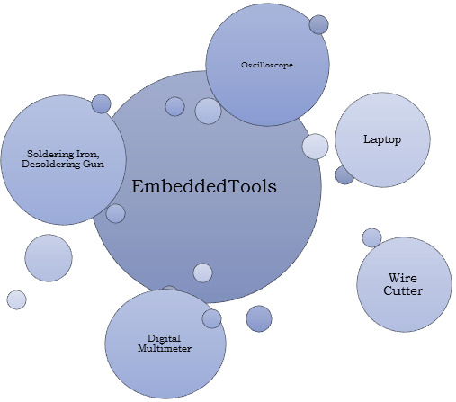
How to Learn Embedded Systems: A Comprehensive Guide
Embedded systems are integral to countless applications, from consumer electronics to industrial automation. Understanding how to learn embedded systems can open up a world of opportunities in various fields, including robotics, automotive, healthcare, and IoT. Here’s a structured approach to mastering embedded systems.

1. Understanding the Basics
Start with the fundamentals of embedded systems. Familiarize yourself with key concepts such as:
What are Embedded Systems?
Embedded systems are specialized computing systems that perform dedicated functions within larger mechanical or electrical systems. Unlike general-purpose computers, they are designed to execute specific tasks with high reliability.
Components of Embedded Systems:
Microcontrollers and Microprocessors: Understand the difference between the two. Microcontrollers are compact integrated circuits designed to govern a specific operation in an embedded system, while microprocessors are the central unit of a computer that performs calculations and logic operations.
Memory: Learn about different types of memory (RAM, ROM, Flash) used in embedded systems.
Input/Output Devices: Familiarize yourself with sensors, actuators, and communication interfaces (UART, SPI, I2C).
2. Choose Your Learning Resources
Select resources that match your learning style. Here are some options:
Books:
"Embedded Systems: Introduction to the MSP432 Microcontroller" by Jonathan Valvano
"Programming Embedded Systems in C and C++" by Michael Barr
Online Courses:
Platforms like Coursera, Udemy, and edX offer courses in embedded systems. Look for those that cover microcontrollers, programming, and interfacing.
YouTube Channels:
Channels like "The DIY Life" and "NPTEL" provide practical insights and tutorials on embedded systems.
3. Get Hands-On Experience
Theory is essential, but hands-on practice is crucial for mastering embedded systems. Consider the following:
Development Boards:
Start with popular development boards like Arduino, Raspberry Pi, or ESP32. These platforms are beginner-friendly and have extensive community support.
Build Projects:
Create simple projects like LED blinkers, temperature sensors, or motor controls. Gradually move to more complex projects like home automation systems or robotic applications.
Use Simulation Tools:
Familiarize yourself with simulation tools like Proteus or MATLAB/Simulink for testing your designs virtually.
4. Learn Programming Languages
Embedded systems often require programming skills. Focus on:
C/C++ Programming:
C is the most commonly used language for embedded systems due to its efficiency and control over hardware. Learn the syntax, data structures, and memory management.
Assembly Language:
Understanding assembly language can provide deeper insights into how microcontrollers operate.
5. Explore Real-Time Operating Systems (RTOS)
Many embedded systems require multitasking and real-time performance. Learning about RTOS concepts can be beneficial:
Understand the Basics:
Familiarize yourself with the concepts of task scheduling, inter-task communication, and resource management.
Hands-On with RTOS:
Try using an RTOS like FreeRTOS or Zephyr on your development board. Implement multitasking projects to get practical experience.
6. Join Online Communities
Engaging with fellow learners and professionals can enhance your learning experience:
Forums and Discussion Groups:
Platforms like Stack Overflow, Reddit, and specialized forums (e.g., Embedded Related) are great for seeking help and sharing knowledge.
Attend Workshops and Webinars:
Participate in online workshops or local meetups to learn from experts and network with peers.
7. Stay Updated with Industry Trends
The field of embedded systems is constantly evolving. Keep yourself updated with the latest trends and technologies:
Follow Industry News:
Subscribe to blogs, newsletters, and magazines related to embedded systems.
Participate in Hackathons:
Engage in hackathons or coding competitions focused on embedded systems to test your skills and learn from others.
Conclusion
Learning embedded systems requires a mix of theoretical knowledge and practical experience. By following this structured approach—starting from the basics, choosing the right resources, getting hands-on experience, and staying engaged with the community—you can build a strong foundation in embedded systems. Whether you aim to work in robotics, IoT, or automation, mastering embedded systems can significantly enhance your career prospects. Start your journey today, and embrace the exciting world of embedded systems!
0 notes
Text
Essential Embedded Software Development Tools for a Smooth Development Process
Embedded software development is a specialized field that requires a unique set of tools to ensure the smooth creation of software that runs on embedded systems, such as microcontrollers and microprocessors. These tools are essential for debugging, testing, and optimizing code for these resource-constrained environments. In this blog post, we’ll explore some of the key embedded software development tools that every developer should have in their toolbox.
Integrated Development Environments (IDEs)
IDEs are the central hub for embedded software development. They provide a comprehensive platform for writing, editing, compiling, and debugging code. Some popular IDEs for embedded development include:
Eclipse: An open-source IDE with a vast ecosystem of plugins, including many tailored for embedded development.
Keil MDK: A dedicated IDE for ARM-based microcontrollers.
IAR Embedded Workbench: A powerful toolchain for ARM, MSP430, and RISC-V processors.
PlatformIO: An open-source IDE that supports multiple platforms, including Arduino, ESP8266, and STM32.
Cross-Compilers
Cross-compilers are essential tools that allow you to write and compile code on a host machine while targeting a different architecture, like an ARM-based microcontroller. These compilers help optimize code for the target hardware. Popular cross-compilers include GCC (GNU Compiler Collection), ARM Keil, and IAR Embedded Workbench.
Debugging Tools
Debugging is a crucial aspect of embedded software development. Without the right tools, finding and fixing bugs can be a daunting task. Some of the tools used for debugging embedded systems are:
JTAG Debuggers: These hardware tools connect to your embedded system and enable you to halt program execution, inspect variables, and trace program flow.
Serial Debuggers: These are essential for debugging when using serial communication with your embedded system.
GDB (GNU Debugger): GDB is a popular open-source debugger that can be used with various IDEs and hardware debuggers.
Real-Time Operating Systems (RTOS)
Many embedded systems require real-time capabilities, and an RTOS is often the best way to achieve this. Popular RTOS options include FreeRTOS, Micrium uC/OS, and VxWorks. These operating systems help manage tasks, priorities, and resources in an embedded system.
Code Analysis and Profiling Tools
Code analysis and profiling tools are essential for optimizing code and identifying potential issues. Tools like Lint, Cppcheck, and Static Analysis Tools can help find code quality and security issues, while profiling tools like Gprof and Percepio Tracealyzer can help identify performance bottlenecks.
Version Control Systems
Effective version control is crucial for collaboration and code management. Tools like Git and SVN help keep track of code changes, facilitate collaboration, and provide a backup for your work.
Simulation Tools
Simulation tools allow you to test your embedded code on a host machine before deploying it to the target hardware. Tools like QEMU and Simulink can help you validate your code without the need for physical hardware.
Documentation and Collaboration Tools
Proper documentation is essential for understanding and maintaining embedded software. Tools like Doxygen can automatically generate documentation from code comments. Collaboration tools like Slack, Microsoft Teams, or even a simple Wiki can help teams work together efficiently.
Conclusion
Embedded software development can be a challenging but rewarding field. Having the right tools at your disposal can make the process much more manageable. Whether you are a beginner or an experienced developer, these tools can help streamline your development process, improve code quality, and ensure the reliability of your embedded systems. Make sure to choose the tools that best suit your project requirements and hardware platform for a successful embedded software development journey.
0 notes
Text
Arduino Education launches four new STEAM products at Bett
During Bett Show 2020, Arduino will launch the Arduino Education learning evolution: four new STEAM products for students in lower secondary school through to university. Arduino Education will also announce a partnership with the Fraunhofer Initiative: “Roberta – Learning with Robots” in Germany.

Arduino Education‘s latest products — CTC GO! Motions Expansion Pack, Engineering Kit Rev2, Arduino Education Starter Kit, and IoT Starter Kit — will be unveiled at Bett and available in Q1. These new products complement the existing portfolio, which includes the Science Kit, CTC GO!, CTC 101, Arduino Starter Kit, and Certification program.
Arduino CEO Fabio Violante comments: “We are delighted to announce four new products which will expand STEAM learning for lower secondary to university students. Our technology, programming, and curriculum content are creative tools — just like brushes and paint — that students can use as they become part of our next generation of scientists and artists.”
CTC GO! Motions Expansion Pack (Age: 14+)

Build on your secondary school students’ STEAM knowledge with more complex programming concepts that develop computational thinking and 21st-century skills.
For educators who have taken their students through the CTC GO! – Core Module, the Motions Expansion Pack builds on what they have already learned about how to use technology as a tool and how to apply that knowledge in the real world. The Motions Expansion Pack challenges students to go a step further in computing and design while introducing them to motors and transmission mechanisms such as pulleys and gear concepts that develop their logical reasoning, hands-on building skills, and problem-solving skills. Educators get all the teaching support they need with webinars, videos, guides, and direct contact with an expert.
Engineering Kit Rev2 (Age: 17+)
Challenge upper secondary school and university students and help them develop hands-on engineering skills.
Educators can challenge engineering students and help them develop physical engineering skills with the Arduino Engineering Kit Rev2. Featuring cutting-edge technology, the kit is a practical, hands-on tool that demonstrates key concepts, core aspects of mechatronics, and MATLAB and Simulink programming. Developed in partnership with MathWorks, The Engineering Kit Rev2 is ideal for advanced high school and college students, the three projects teach the basics of engineering — plus they’re fun to do!
Education Starter Kit (Age: 11+)

Learn electronics and get started with programming in your classroom step-by-step — no experience necessary!
Educators can teach lower secondary school students the basics of programming, coding, and electronics. No prior knowledge or experience is necessary as the kits guide educators through step-by-step, they are well-supported with teacher guides, and lessons can be paced according to students’ abilities. The kit can be integrated throughout the curriculum, giving students the opportunity to become confident in programming and electronics with guided sessions and open experimentation. They’ll also learn vital 21st-century skills such as collaboration and problem-solving.
IoT Starter Kit (Age: 14+)
The first step into the world of connected objects has never been easier.
Advanced secondary school and university students can get started with the Internet of Things quickly and easily. They’ll learn about using sensors; automation; logging, graphing and analyzing sensor data, and triggering events with serious technology made simple. The kit contains step-by-step tutorials for ten different projects – fun, creative experiments using real-life sensors.
In partnership with the Fraunhofer Initiative: “Roberta – Learning with Robots”
youtube
The dream team for classrooms worldwide: Arduino Education has officially partnered up with the Fraunhofer Initiative “Roberta – Learning with Robots.” The Arduino Uno WiFi Rev2 board, part of Arduino CTC GO!, joined the Open Roberta Lab, the biggest open-source coding platform developed in Europe.
The Arduino Uno WiFi Rev2 is the fourth Arduino board to be integrated into the Open Roberta Lab, which currently supports 13 robots and microcontrollers that enable children worldwide to adopt a playful approach to coding. The lab is the technological component of the Roberta Initiative, which was started by Fraunhofer IAIS in 2002. Eighteen years’ experience in STEM education, training teachers, and developing materials as well as launching the Open Roberta Lab in 2014 make Roberta a one-of-a-kind initiative in Germany and beyond, and the perfect partner for Arduino Education.
“Fraunhofer offers guaranteed quality, both on the technical level as well as for community support,” says Arduino CTO David Cuartielles. “There are a lot of synergies in our cooperation. Roberta is really meant for teachers to learn how to teach technology, and that’s also a key part of Arduino Education’s mission.”
“Open Roberta is developed as an open source platform to engage a community worldwide to join our mission. As a popular open source electronics platform, Arduino is the perfect match for us as it also motivates people all over the world to develop their own ideas and move from using to creating technology,” adds Thorsten Leimbach, head of business unit “Smart Coding and Learning” and Roberta manager at Fraunhofer IAIS.
Arduino Education launches four new STEAM products at Bett was originally published on PlanetArduino
1 note
·
View note
Photo

On the occasion of Engineers' Day, a Hands-on Workshop on "Internet of Things" has been conducted by COE (Ni & e-Yantra) & IEEE student branch, ECE Department. The workshop was inaugurated by Head of Department Prof. Monika Jain, and she also felicitated the eminent speaker "Mr. Ashish Kumar" who is the director in Verve Gen Tech. Pvt. Ltd. Today was the second day of this workshop. The Hands-on session continued in Centre of Excellence NI (COE). He demonstrated various interfacing devices with Arduino and also illustrated simulink software Proteus. He also gave the introduction of Thing Speak. The session was very helpful for the students. The valedictory session was delivered by Head of Department Prof. Monika Jain. #EngineersDay #COE #IEEE #ios #appleios #apple #mobile #centerofexcellence #coe #technology #education #btech #engineering #itsengg #itsengggn #certificationcourses #admission #admissionopen #admission2022
0 notes
Text
Want to Learn the integration of Arduino with MATLAB? Read this Blog and understand the Basic Input/Output Commands for Arduino using MATLAB & Simulink. Now you can create a Simulink Model and configure the Arduino without even writing a single line of code.
0 notes
Text
Embedded Controls Development: From Design to Deployment

Embedded controls development is a critical area in embedded systems engineering, involving the design, programming, and integration of control systems into hardware platforms. These systems are typically found in devices that perform dedicated functions, ranging from consumer electronics to industrial automation and automotive applications. The development process requires a combination of hardware knowledge, software engineering, and systems integration skills.
What Are Embedded Controls?
Embedded controls are computer-based systems that control specific functions within a larger mechanical or electrical system. They use microcontrollers, digital signal processors (DSPs), or microprocessors to monitor inputs from sensors, process data according to a control algorithm, and output control signals to actuators or other system components. These control loops can be simple (like turning on a fan when a sensor detects high temperature) or complex (like managing engine timing and fuel injection in modern vehicles).
Development Lifecycle
The development lifecycle for embedded controls typically follows several key stages:
Requirements Definition: Understanding what the control system needs to do. This includes identifying input/output interfaces, environmental constraints, performance requirements, and safety or compliance standards.
System Design: Creating a high-level architecture that defines how software and hardware will interact. This stage also involves choosing the right microcontroller or processor, selecting sensors and actuators, and outlining communication protocols.
Software Development: Writing code for the embedded control system, often in C or C++. Developers must consider memory limitations, real-time constraints, and hardware-specific details. This stage includes implementing control algorithms, handling interrupts, and developing communication interfaces such as I2C, SPI, UART, or CAN.
Hardware Integration: Integrating the embedded software with physical components. This includes setting up the development board, connecting sensors and actuators, and testing signal integrity and power consumption.
Testing and Validation: Rigorously testing the control system to ensure it functions as expected under various conditions. Unit testing, integration testing, and hardware-in-the-loop (HIL) simulations are commonly used to verify performance and reliability.
Deployment and Maintenance: After development and testing, the system is deployed into the final product. Ongoing maintenance may involve firmware updates, bug fixes, or performance improvements.
Tools and Platforms
A wide range of tools are used in embedded controls development, including:
Integrated Development Environments (IDEs): Tools like Keil µVision, MPLAB X, STM32CubeIDE, and Arduino IDE are popular for writing and debugging code.
Real-Time Operating Systems (RTOS): Systems such as FreeRTOS or VxWorks provide scheduling, task management, and synchronization capabilities for time-sensitive applications.
Version Control Systems: Git is widely used to manage code versions and support collaborative development.
Simulation and Modeling Tools: MATLAB/Simulink is frequently used in control systems design for simulation and code generation.
In-Circuit Debuggers/Programmers: Tools like JTAG or SWD interfaces allow developers to program and debug the target microcontroller directly.
Challenges in Embedded Controls Development
Developing embedded control systems presents several challenges:
Resource Constraints: Embedded systems often have limited CPU power, memory, and energy availability. Efficient coding and hardware optimization are essential.
Real-Time Requirements: Many control systems must respond within strict timing constraints. Missed deadlines can result in system failure or unsafe behavior.
Hardware Dependence: Embedded software is closely tied to specific hardware, requiring deep knowledge of the processor, peripherals, and electrical characteristics.
Debugging Complexity: Diagnosing problems in embedded systems can be difficult due to limited visibility into internal states and limited logging capabilities.
Safety and Reliability: In industries like automotive or medical devices, the control systems must meet rigorous safety standards such as ISO 26262 or IEC 62304.
Applications
Embedded controls are used in countless applications:
Automotive Systems: Engine control units (ECUs), anti-lock braking systems (ABS), adaptive cruise control, and infotainment systems.
Consumer Electronics: Smart thermostats, washing machines, and robotic vacuum cleaners all rely on embedded control systems.
Industrial Automation: PLCs and industrial controllers manage processes on factory floors, often integrating with SCADA systems.
Aerospace and Defense: Flight control systems, unmanned aerial vehicles (UAVs), and radar systems.
Medical Devices: Infusion pumps, pacemakers, and diagnostic equipment all include embedded control systems to ensure safe and accurate operation.
Trends and Future Directions
The field of embedded controls is rapidly evolving. Several key trends are shaping the future:
IoT Integration: Many embedded systems are now connected to the internet, allowing for remote monitoring, control, and firmware updates.
Edge Computing: More processing is being done on the device itself, reducing the need to send data to the cloud and improving response times.
AI and Machine Learning: Embedded systems are beginning to incorporate ML algorithms for pattern recognition, predictive maintenance, and adaptive control.
Model-Based Design: Tools like Simulink allow engineers to design control systems graphically and automatically generate embedded code.
Cybersecurity: As systems become more connected, securing embedded control systems against hacking and data breaches is becoming essential.
Conclusion
Embedded controls development by Servotechinc is a complex but vital discipline that sits at the heart of modern technology. From managing vehicle dynamics to enabling smart home features, embedded control systems play a crucial role in ensuring that machines operate efficiently, safely, and intelligently. As technology advances, the demand for skilled engineers in this domain will only continue to grow.
0 notes
Photo

Modeling of DC Motor and Choosing the Best Gains for PID Controller
by Ye Htet Aung | Tin Tin Hla ""Modeling of DC Motor and Choosing the Best Gains for PID Controller""
Published in International Journal of Trend in Scientific Research and Development (ijtsrd), ISSN: 2456-6470, Volume-3 | Issue-5 , August 2019,
URL: https://www.ijtsrd.com/papers/ijtsrd26636.pdf
Paper URL: https://www.ijtsrd.com/engineering/electronics-and-communication-engineering/26636/modeling-of-dc-motor-and-choosing-the-best-gains-for-pid-controller/ye-htet-aung
call for paper health science, ugc approved engineering journal, social science journal
NAMIKI 12 volt DC motor is used to model mathematically. L298 N hybrid motor driver is used to drive the motor. Voltage for the motor to drive to the desired angle is applied from the PWM of the motor. The best PWM value for the motor is considered by using PID controller from the Arduino processor. The actual angle of the motor is get from the optical encoders. The best gain for PID controller is get from Ziegler Nichols method and Simulink of MATHLAB software by using mathematical modelling equation of the motor. The modelling equation is get from two kinds of calculation. The first approach is from parameters estimation of the motor. The second is from first order differential equation. Then, the best PWM value is get for the position control of the motor. This motor is used for the robot arm.
0 notes
Text
(1) System Dynamics & Vibration Paper Project Report Second Order Mechanical System Landing Gear of an Aircraft By Saad Ali Hassan and Beatrice

1 Introduction
1.1 Mechanical Part
Landing gears, also known as undercarriage, are mechanisms designed to support the overall weight of the aircraft (body of airplane + passengers + stowed bags and hand carriage) when the vehicle is still grounded and to withstand extremely high loads during landing without damage to its structure while providing comfort and safety to the passengers on board. In resume, a landing gear is the mechanical system that allows the craft to land, take-off or even taxi.
1.1.1 Background
The landing gear mechanism is extremely important to the overall performance of the aircraft. Even under rigorous and regular maintenance, failure still happens on aircrafts and even the smallest malfunction on the landing mechanics can account for those failures that can cause danger to the passengers and crew. Because of that, the right choice of strong materials for the structure of the mechanism and the correct assembly of each component of the system are of extremely importance. The material of the structure must have high static strength as well as good fracture toughness and fatigues strength to withstand the load and the high impact that happens during landing; therefore, some good choices might include high-strength steel and titanium alloys.
1.1.2 Simplified Selected System for Analysis
Landing gears are known for being quite a complex system with many different primary components and some secondary components that are attached to its body and that function with the landing gear during the operation of the aircraft such as steering devices and retracting mechanisms which will act during tax and after the airplane has departed). The image below illustrates the complexity of this mechanism.
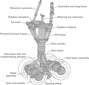
Because of the complexity of the mechanism, a simplified version of a landing gear can be used during analysis like the one approached in this report. This simpler mechanism contains a mass (m) representing the overall weight of the aircraft, a spring (K) and a dumper (B, or in the image 'C') which are all suspended by a wheel that results on the horizontal movement of the plane. This simplified version can be seen on the image below and that is the system that will be constantly referred in this project report.
1.1.3 System Physical Decomposition
The simplified system that has been approached has three main components. They are dumper, spring and mass. Each one of these components play a very important role in the operation of the mechanism.
The damper, also known as shock absorber, is a hydraulic device designed to
dissipate kinetic energy and weaken the impact
in a certain structure.
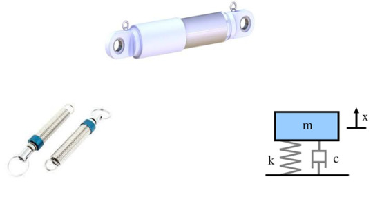
The spring represent the elasticity of the system; it converts the force input into mechanical displacement. In the landing gear mechanism, the spring used to create retraction and elasticity.
The mass of the system is what creates the inertia force which is the resistance to any change in velocity. This mass is represented by the total aircraft weight on the landing gear mechanism.
1.1 Additional Electrical Part
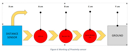
The distance measurement sensors are used in several engineering application including measuring liquid levels in tank, precise movement of robot arms in an automated production line, detection of people or object from a reference, measurement of object distances in outdoor and indoor environments. These sensors are electronically controlled and are very accurate in their measurements. The system of an aircraft uses a diverse range of sensors that provide critical assistance and feedback information in piloting, maintaining and communicating with the aircraft itself. These sensors work altogether to create a safe and effective operation of an aircraft. The report will investigate the ultrasonic distance sensor as prototyped, which is used in measuring distance to the point of interest (ground level) in an aircraft.
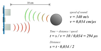
1.1.1 Background
The ultrasonic distance (HC-SR04) sensor emits an ultrasound at 40 000 Hz which travels through the air and if there is an obstacle on its path it will bounce back to the module. Considering the travel time and the speed of the sound it is possible to calculate the distance from the object to the sensor. The ultrasonic distance sensor comes in two types. Proximity detection, an object passing within the pre-set range will be detected and generate an output signal. The detect point is independent of target size, material or reflectivity. Ranging measurement, precise distance(s) of an object moving to and from the sensor are measured via time intervals between transmitted and reflected bursts of ultrasonic sound. Distance change is continuously calculated and outputted.
1.1.1 Simplified Selected System for Analysis
Due to the the extent of complexity in the project, the electrical system is self-customized to follow the main learning aspect of the project that it is portraying (read Objective heading below) while avoiding the factors that are not necessary to execute the practical demonstration and the reflect learnings. The selected electrical system consists of an Arduino board, LED, buzzer, resistor and an ultrasonic distance sensor HC-SR04 used in a proximity detection mode.
1.1.2 System Physical Decomposition
The Arduino board module is an open-source micro-controller which is the main component to the electrical part. It is powered through a 9V battery and acts as a computer in operating the other sub modules attached to it. The LED and buzzer are used to provide a ‘get ready’ and ‘warning’ signal feedback respectively as the distance sensor output signal changes comparing the set values in code. All of which is controlled and programmed in the microcontroller.
1 Objective
The objective of this project is to combine the mechanical and electrical parts to produce a second order electromechanical system and depict its combined function through prototyping and using the concept of a landing gear mechanism of an aircraft. This will investigate further into the transfer functions, mathematical equations, block diagrams and its active system parameters that involves in producing the desired output action from an input along with evidences using Simulink models and the prototype designed.
2 Scope of the Project
The project provides a learning opportunity to students pursuing the understanding in System Dynamics. The designed prototype shows the basic way how efficiently an electrical system’s output element relates to a mechanical system’s feedback input element practically in order to operate in an effective manner. The theoretical and mathematical part is there to prove the functionality of the prototype.
3.1 Future Work
Modification can be made in the prototype to enhance and increase the learning experience gained by the students. It is recommended to add a feature of auto-retraction of the wheel as the ground approaches. This practice could be applied by introducing a servo motor that is well connected with the retraction mechanism, and as the sensor sends out the ‘close to ground’ signal to the Arduino board, the board should enable the configured servo motor to retract the wheel and prepare for landing. This would allow another element of study to the project and extend its future scope.
3 Constraints and Assumptions
For doing the analysis on the system, we consider the following assumptions for the values of the parameters in the given system. For simplicity these values are taken from problem A-4-18 in the book. To obtain the responses curve in the report further we assume:
M = 100kg
B = N-s/m
K = 800 N/m
Wn = 1 rad/sec
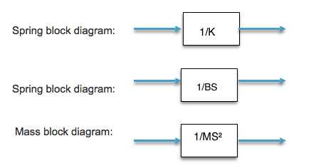
1 Block Diagram for All System Components
1 Mathematical Equations of the Subsystem and System
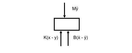
The simplified second order mechanical system consist of the following parameters in the absence of any external forces (P). Below is the free body diagram:
Figure 9 FBD of System 2
1.1 Damper Equation
Where B is the damping coefficient, ẋ and ẏ are the velocities.
1.2 Spring Equation
Where K is the spring constant, x and y are the distances.
1.3 Inertia Force Due to Mass
Where M is the mass of the plane, and ÿ is the acceleration.
1.4 System Equation
Using Newton’s second law, sum of all forces, taking upward direction as positive:
1.5 System Equation with External Force
Using Newton’s second law, sum of all forces, taking upward direction as positive:
2 Derived Transfer Functions
The transfer function is defined as the output resulted from a certain input.
2.1 Y(s)/X(s)
This transfer function can be defined in simple words, how much X(s) displacement is to be applied to get Y(s) displacement.
Applying Laplace Transform with zero initial conditions
3 Simulink Model of the Entire System
The Simulink model of the system is referenced from the problem A-4-18 of course book. The second order mechanical system’s transfer function equations are shown in the standard from below after applying the assumed values. Further the system is analyzed by observing the output responses to certain standard input responses below.
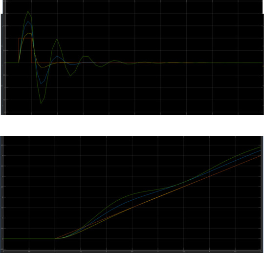
3.1 Step Response
The step response of a system is one of the most important and basic response for a system that has initial conditions as zero. Our prototype was tested by a unit response of the displacement caused by the landing impact (X(s) = 1) and how it made its effect to the displacement after the shock absorber placed (Y(s)). We derived the following transfer function to test it using Simulink.
3.2 Ramp Response

1.1 Step Response
Step, Over Damped, Critically Damped and Under Damped
1.1 Ramp Response
Ramp, Over Damped, Critically Damped and Under Damped
1.1 Frequency Response Sinusoidal
Sinosoidal, Over Damped, Critically Damped and Under Damped

1 Conclusion
It can be concluded from this project and report that the landing gear follows the same principle as a simple second order system composed by a spring, mass and damper. The springs provides elasticity to the mass which in this case represents the body of the aircraft and its passengers; the damper, also known as shock absorber, makes the impact on the airplane weaker by dissipating the concentrated kinetic energy and the mass provides the inertia force for the system which is key in any type of motion.
As it was experimented using the landing gear prototype and Simulink, graphs were produced and mathematical calculations were performed in order to analyze the response of the system under conditions like underdamped, overdamped and critically damped conditions while changing the inputs of the system. As we want a system that quickly response to transient response and reach a steady state value with small settling time, we tend to prefer a over damped dumper for our landing gear prototype.
In addition to the mechanical system a distance sensor and motor was also attached to the landing gear prototype which gives the system an element of control signal, to release the wheel as the mechanism approaches the ground level.
With regards to the different types of inputs, when there is a step input of 1 being applied to the X displacement, the Y displacement changes accordingly with different values of zeta, damping ratio. As it is shown in the graph, Y should reach the steady state in the shortest period what happens when the least amount of disturbance is observed. In other words, it is desirable that the consequent output has a value that is relatively close to the input. As we follow to the ramp input, the different responses from different values of zeta are observed. We can also observe the time delay between the input and output response as it is the area between the two responses. The response increases proportional to the time. The error between the input and output is gradually decreased as the output slowly reaches the steady state value.
With the impulse response the system’s oscillations quickly variate from maximum to minimum values. However, this difference becomes smaller and smaller as the transient response dies out over time as the output reaches a steady state value. Finally, with the sinusoidal response, if the input is sinusoidal, the output will be sinusoidal as well, but the value will be shifted by theta what can be easily observed by looking at the graph inserted in this report.
0 notes
Text
EEG Sensor Research
We started by researching what type of software there was available to make sure it was plausible to achieve our idea.
Recommended by: https://makeitmech.com/material-required-for-portable-eeg-system-development/
Multisim: Multisim is simulation software for various designs. This software is widely used because almost all required components are available in it. It is a tool used for testing various programs, simulations and complex electronics designs. It is also used for schematic designing and capture and for PCB (Printed Circuit Board) designing. We have used multisim for developing simulation circuits for Main Board and all other 3 stages of the circuit. PCB is also designed using the same software. - Has a free variation with less options
MATLAB: MATLAB is used for real time signal plotting. We used MATLAB as a tool for analyzing real time signal. AS the signal was quite noisy and fluctuating so we used MATLAB scope to plot the signal in real time. MATLAB is platform for mathematics and all types of functions and signal processing. WE can also use MATLAB for further signal processing. We used only the Simulink part of the MATLAB for Arduino board values. - Has a one month free trial avalible
Arduino IDE: The Arduino IDE is the software for Arduino development board. The Arduino IDE is used for writing Arduino Code for the EEG circuit. The Arduino code to identify the threshold values of ADC and averaging the EEG signal values. - the free arduino coding software
Recommended by: http://openeeg.sourceforge.net/buildeeg/software.php
BWView (http://uazu.net/bwview/)
This application, released as free software under the GNU GPL v2 for Linux and Windows, is designed for getting a rapid visual understanding of recorded brain-wave data. It uses FFT-accelerated convolution to do the analysis, which enables much greater flexiblity than using the traditional FFT-of-windowed-data approach. The frequency is plotted on a log scale, which is much better for viewing data that includes a wide range of frequencies. The window size is proportional to the wavelength at any frequency, so the convolution is effectively being done with a complex wavelet at various different scales. The ratio of window size to wavelength can be varied easily to allow different aspects of the data to be shown. Features:
Visually displays EEG data.
Platforms: Linux, Windows
This told us that there were many different Software that would be adequate to help us in our project. We then looked into existing headsets that use EEG:
When looking at these headsets it appeared that comfort and accuracy would be the main issue. Most headsets that exist currently are made of a hard plastic and are not comfortable to wear for extended periods of time.
Products such as Muse (https://choosemuse.com/) are used to monitor brainwaves to assist meditation and utilize a conductive rubber for added comfort. However, there is still a hard metal band for the sensors which would not be comfortable to sleep in.

Products like Emotiv (https://www.emotiv.com/) highlight the fact that the use of gels and liquids increases the accuracy of the readings. This means that electrodes constantly need replacing and also the added discomfort of liquids on the head during sleep makes this approach unlikely to be plausible for our idea. This means our readings will never be as accurate as they can be.

Even Sleep Shepherd (https://sleepshepherd.com/) a device already designed to sleep in looks bulky and has hard pieces that would make some sleeping positions highly uncomfortable. The use of soft materials however does show us that our idea is plausible.

Who did what?
Research: Steph
0 notes