#arduino uno project documentation
Explore tagged Tumblr posts
Visit Tumblr Blog
Explore Tumblr blogs with no restrictions, modern design and the best experience.
Last Seen Tumblr Blogs


Fun Fact
Users from the US are the majority of Tumblr visitors.
Text
Top 5 Home Automation Electronics Kits for Beginners in 2025
Home automation is changing the way we live, making everyday tasks easier and more efficient. From controlling lights to setting up security systems, smart technology is transforming our homes. If you're just starting to explore this exciting field, one of the best ways to dive in is with a home automation electronics kit. These kits give you the chance to learn and create your own smart home solutions.
In this article, we will explore the top 5 home automation electronics kits for beginners in 2025. Whether you’re new to electronics or just starting to get into home automation, these kits offer a great introduction to the world of DIY smart homes.
1. Arduino Starter Kit for Home Automation
What It Is:
Arduino is one of the most popular platforms for creating home automation projects. The Arduino Starter Kit includes an Arduino board, a variety of sensors, and all the necessary components to start building your first smart home devices.
Features:
Complete Kit: Includes the Arduino Uno board, wires, LEDs, temperature sensors, and more.
Easy Tutorials: Many beginner-friendly guides and projects are available online.
Open-Source: You can freely modify and improve your projects as you gain more experience.
Large Community: Lots of support and advice from other users.
Why It’s Great for Beginners:
Affordable: It’s one of the cheaper options for home automation kits.
Simple Programming: The programming language (C++) is beginner-friendly and well-documented.
Expandable: As you learn, you can add more sensors and devices to your projects.
Example Projects:
Automate lights with motion sensors.
Control a fan based on temperature.
Build a smart lock system using an RFID sensor.
2. Raspberry Pi 4 Home Automation Kit
What It Is:
The Raspberry Pi 4 is a small but powerful computer that can be used to control and manage your home automation system. With this kit, you’ll have the tools to run automation software and integrate smart devices.
Features:
Powerful Processor: The Raspberry Pi 4 has strong performance for handling complex tasks.
Versatile Software: It runs Raspberry Pi OS, which supports different home automation programs.
Connectivity: It includes Wi-Fi, Bluetooth, and Ethernet options to connect to your devices.
Complete Kit: Comes with a Raspberry Pi 4, power supply, pre-loaded SD card, and cooling accessories.
Why It’s Great for Beginners:
User-Friendly: Despite its power, the Raspberry Pi is beginner-friendly with lots of helpful tutorials.
Affordable: A powerful option that doesn’t cost a lot.
Expandable: You can add extra sensors, cameras, and devices as you go.
Example Projects:
Build a smart home dashboard to control all your devices.
Create a home security system using cameras and motion sensors.
Design a smart thermostat that adjusts the temperature based on the weather.
3. Sonoff DIY Smart Home Kit
What It Is:
Sonoff is known for offering simple and affordable home automation solutions. The Sonoff DIY Smart Home Kit includes smart plugs, switches, and a hub that can be easily controlled using a smartphone app.
Features:
Smart Plugs & Switches: Control your home appliances remotely through the eWeLink app.
Voice Control: Works with Alexa and Google Assistant for voice commands.
Cloud Control: Control devices from anywhere using the internet.
Wide Compatibility: It works with most home appliances.
Why It’s Great for Beginners:
Simple Setup: You don’t need to deal with complicated wiring—just plug in your devices and start using them.
No Programming Required: The app makes it easy to control devices without any technical skills.
Affordable: The kit is budget-friendly, making it an excellent entry point for beginners.
Example Projects:
Set up a lighting system that turns on based on motion or time.
Automate appliances like coffee makers and fans.
Use a motion sensor to trigger a lamp to turn on when someone enters the room.
4. Makeblock mBot Ultimate 2.0 Robotics Kit (with Home Automation Projects)
What It Is:
The Makeblock mBot Ultimate 2.0 is primarily a robotics kit but can also be used to create home automation projects. It’s a great option for beginners who want to learn both robotics and automation.
Features:
Includes Sensors: Comes with motion, temperature, and light sensors.
Visual Programming: Uses mBlock, a drag-and-drop programming tool based on Scratch, making it easy to learn coding.
Modular Design: You can add different parts to customize your projects.
App Control: The mBot can be controlled using a mobile app, allowing you to set up automated routines.
Why It’s Great for Beginners:
Educational: Combines fun robotics with practical home automation skills.
Easy to Program: The visual programming interface is beginner-friendly.
Customizable: You can build different types of projects, including home automation systems.
Example Projects:
Set up a security system with motion detection and video.
Build a smart pet feeder that can be controlled from your phone.
Create a lighting system that turns on or off based on occupancy.
5. Tinkr Home Automation Kit
What It Is:
The Tinkr Home Automation Kit is a beginner-friendly kit designed for easy setup and control of smart home devices. It comes with various sensors, smart plugs, and a user-friendly app.
Features:
Complete Kit: Includes motion, light, and temperature sensors, as well as smart plugs and switches.
Easy-to-Use App: The Tinkr app makes it simple to control your devices and set up automation routines.
Cloud Control: Allows you to control your devices from anywhere using the internet.
Wireless: Uses Wi-Fi or Zigbee for easy connections with smart devices.
Why It’s Great for Beginners:
Plug-and-Play: No complex wiring—just follow the instructions in the app.
Simple Interface: The app’s interface is designed to be easy for beginners.
Affordable: It’s a great value for those just getting into home automation.
Example Projects:
Set up smart lighting that adjusts based on room occupancy.
Automate your air conditioning system to turn on when the temperature reaches a certain level.
Build a smart garden irrigation system that activates when the soil is dry.
Conclusion
As home automation becomes more popular, there are plenty of options for beginners to explore. The kits listed here offer an accessible and hands-on way to learn about smart technology and electronics. Whether you choose a simple option like the Sonoff DIY Smart Home Kit or a more powerful solution like the Raspberry Pi 4, each of these home automation electronics kits provides a great starting point for your smart home projects.
By diving into home automation, you’ll not only be able to make your home smarter and more efficient, but you’ll also gain valuable skills in electronics, programming, and problem-solving. So, pick your favorite kit, get started, and enjoy the process of creating your own smart home!
0 notes
Text
I want to document a robot building but have no idea what to do
For tools I have:
Screwdrivers
scissors
wirestripper
tweezers
box cutter
Materials:
x8 HC-SR04 sonar sensors
x4 boxes worth of cardboard
x4 arduino unos microcontrollers (One an Arduino, three Egloos)
x3 arduino nanos a whole lot of jumper wires
x4 9 v batteries
x4 rolls electrical tape
x4 28BYJ-48 5v dc stepper motors with connectors to breadboards
x6 breadboards
An assembled arm, composed of metal and screws for the body, x6 MG 996R motors for moving joints, connected to a PCA 9685
I don't have any coding experience besides copy and pasting onto the nano and the uno, but I would like a project idea which involves at least the sonar sensors, if anyone has suggestions, please let me know. I don't want to disassemble the arm but if there is a good point made, I would be willing to oblige.
I will also post if I was able to make a sonar detector, I am only really having trouble with the coding, but I will try to get over that hump when I get to it.
EDIT: I PUT TO LONG FOR THE POLL AND I CANNOT SEE THE CURRENT VOTE, I AM PUTTING ONE DOWN FOR THE FIRST ONE SO I CAN SEE IT BECAUSE I AM IMPATIENT
#robots#robotics#robot#stepper motor#arduino#robotics concept#engineering#I mean it might be engineering I guess#like eating mushrooms is considered “biological study” maybe#mechanical engineering#would that be it#idk what I am doing#I love beluga whales#that melon on its forehead#I enjoy people brushing it and it just sort of “boo womp” because its just a lump of fat used for echolocation
1 note
·
View note
Video
youtube
Design & Implementation of an Automated Reminder Medicine for Old People in Hospitals Using Arduino | Design and implementation of Automatic Medicine Reminder Using Arduino with GSM - SMS Alert | Design of Automatic Medication Dispenser | Automatic Pill Dispenser | Design and implementation of automatic medicine dispensing | Design and Implementation of Hospital Automatic Nursing | IOT based Medicine Reminder System with Email Alert. *********************************************************** If You Want To Purchase the Full Working Project KIT Mail Us: [email protected] Title Name Along With You-Tube Video Link We are Located at Telangana, Hyderabad, Boduppal. Project Changes also Made according to Student Requirements http://svsembedded.com/ https://www.svskits.in/ http://svsembedded.in/ http://www.svskit.com/ M1: +91 9491535690 M2: +91 7842358459 We Will Send Working Model Project KIT through DTDC / DHL / Blue Dart / First Flight Courier Service We Will Provide Project Soft Data through Google Drive 1. Project Abstract / Synopsis 2. Project Related Datasheets of Each Component 3. Project Sample Report / Documentation 4. Project Kit Circuit / Schematic Diagram 5. Project Kit Working Software Code 6. Project Related Software Compilers 7. Project Related Sample PPT’s 8. Project Kit Photos 9. Project Kit Working Video links Latest Projects with Year Wise YouTube video Links 157 Projects https://svsembedded.com/ieee_2022.php 135 Projects https://svsembedded.com/ieee_2021.php 151 Projects https://svsembedded.com/ieee_2020.php 103 Projects https://svsembedded.com/ieee_2019.php 61 Projects https://svsembedded.com/ieee_2018.php 171 Projects https://svsembedded.com/ieee_2017.php 170 Projects https://svsembedded.com/ieee_2016.php 67 Projects https://svsembedded.com/ieee_2015.php 55 Projects https://svsembedded.com/ieee_2014.php 43 Projects https://svsembedded.com/ieee_2013.php 1100+ Projects https://www.svskit.com/2022/02/900-pr... *********************************************************** 1. Smart Medicine Reminder Box | e-pill Medication Reminders, 2. MeDuino - Automatic Medicine Reminder. Arduino diy, 3. Medicine Reminder using Arduino by Saddam Khan, 4. Smart Medicine Box, 5. Arduino Uno based Medicine reminder project, 6. Pill Reminder with Arduino version, 7. Automatic patient medicine reminder system || Best project center in Bangalore, 8. Automatic Pill Reminder Using Arduino uno, 9. Raspberry Pi Based Speaking Medication Reminder Project, 10. IoT Based Smart Medicine Box, 11. Medicine Reminder simulation on proteus, 12. Automatic Medicine Reminder with date using Arduino, 13. Medicine reminder, 14. Smart Medicine Pill Reminder IOT Project using Aurdino, 15. Medicine Reminder Box Using Arduino, 16. Smart Medicine Dispenser, 17. Medicine reminder/Alarm using Arduino, 18. MedBox: Smart Medication Box with Arduino - self test, 19. Medicine Reminder System | Smart Medicine Pill Reminder Project, 20. Medicine reminder using Arduino, 21. Best Medicine Reminder DIY, 22. Explanation of our Medicine Reminder Project, 23. SmartSF Smart Pill Box, 24. Medication Reminder using PIC Microcontroller, 25. Medicine Reminder Using Home Made Arduino, 26. Medicine Reminder System Using Microcontroller, 27. ANDROID APP BASED SMART MEDICATION REMINDER SYSTEM, 28. IOT Based Medicine Reminder System with Email Alert, 29. Simulation: Photoresistor-based Smart Pill Dispenser | Schematic Diagram, Arduino Code & Simulation, 30. PILL REMINDER USING ARDUINO BOARD, 31. Pill Reminder Using Raspberry Pi, 32. Our first mini project(Vishva- automatic medicine reminder), 33. Automatic Medication Reminder for People to Take Medicines in Time, 34. Arduino Automatic Medicine Reminder, 35. smart medicine reminder using arduino, 36. Medicine reminder using arduino, 37. Medicine Reminder for Elder people, 38. Renesas: Smart Medicine Box, 39. Smart Medicine Box App, 40. Medicine Reminder System Using Arduino, Design
0 notes
Text
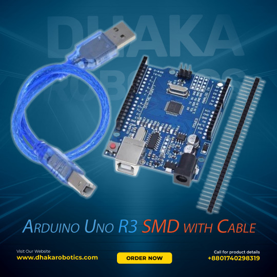
Unleash Your Creativity with Arduino Uno R3 SMD!
Are you ready to dive into the world of electronics and coding? The Arduino Uno R3 SMD is your perfect companion!
Microcontroller: ATmega328P - Digital I/O Pins: 14 (6 PWM outputs) - Analog Inputs: 6 - Clock Speed: 16 MHz - USB Connection & Power Jack Whether you’re a beginner or a seasoned maker, the Arduino Uno R3 SMD offers endless possibilities for your projects. From robotics to home automation, this board has got you covered. Plus, with its robust design and extensive documentation, you’ll be up and running in no time! Click here to purchase the product: https://dhakarobotics.com/…/1004-arduino-uno-r3-smd…/ Contact Us: +8801740298319 visit our website: https://dhakarobotics.com/
0 notes
Text
UNINTERRUPTED AND REMOTE CONTROLLING OF SMART DEVICES
UNINTERRUPTED AND REMOTE CONTROLLING OF SMART DEVICES
Uninterrupted and Remote controlling of smart devices
How many of us wondered if we had turned off the gas or switched off the heater after leaving our houses? It is likely that the number in affirmation is going to be pretty high. While these little mind tricks are common to us all, in today’s modern, technologised households, the dilemma has taken a novel turn.
Many of us are dependent on the…
View On WordPress
#advantages and disadvantages of smart homes#app control switch#arduino thesis pdf#arduino uno project documentation#benefits of smart homes#bluetooth based home automation using arduino#electric wifi#home automation switches india#home automation using arduino and android pdf#home automation using arduino and wifi pdf#home depot home security#home security blogs uk#how do smart homes work#introduction to home automation#iot smart home project#login vector#residential lighting control systems#security vector#smart hd wifi camera#smart home doorbell#smart home introduction#smart homes technology#smart lighting products#smart switch amazon#switch with wifi#UNINTERRUPTED AND REMOTE CONTROLLING OF SMART DEVICES#vector security blog#vector tech support#wifi electrical switch india#wireless ceiling light home depot
0 notes
Text
Arduino-powered ornithopter takes to the skies!

While much less common than quadcopters or airplanes, if you want a device that truly soars like a bird, you need an ornithopter. To help others make their own flying contraption, YouTuber Amperka Cyber Couch is outlining the build process in a video series starting with the one seen below.

Construction is also very well documented in his project write-up, and a clip of it in-flight can be found here. The bionic ‘bird’ uses a BLDC/ESC combination to turn a gearbox that flaps its wings, and an onboard Arduino Nano for control.
Communication is via an MBee 868 wireless module, which links up to an Arduino Uno base station that provides its user interface.
youtube
Arduino-powered ornithopter takes to the skies! was originally published on PlanetArduino
1 note
·
View note
Text
Arduino camera timer trigger

#ARDUINO CAMERA TIMER TRIGGER CODE#
#ARDUINO CAMERA TIMER TRIGGER FREE#
If ((TIFR1 & bit (TOV1)) & timer1CounterValue
#ARDUINO CAMERA TIMER TRIGGER CODE#
The example code below provides a "frequency counter" which counts the number of events which cause a rising edge on digital pin D5 during a specified interval.įor example, if you put a 5 kHz signal on pin D5, and time it for one second, the count will be 5000. You can use these timers easily enough by using the analogWrite function - that just generates a PWM (pulse width modulated) output on the various pins that the timer hardware supports.īut for a more in-depth analysis, let's look at using the timers/counters in our own way. This provides you with the figure that the millis() function returns. This is used to count approximately every millisecond. Timer 0 is set up by the init() function (which is automatically called by the code generated by the IDE, before setup() is called). The Atmega328 (as on the Arduino Uno) has three timers/counters on-board the chip. A project collaboration and documentation platform.This page can be quickly reached from the link:.Membership connects and supports the people and projects that shape our future and supports the learning initiatives for the next generation of makers.
#ARDUINO CAMERA TIMER TRIGGER FREE#
A free program that lights children’s creative fires and allows them to explore projects in areas such as arts & crafts, science & engineering, design, and technology.
Maker-written books designed to inform and delight! Topics such as microcontrollers including Arduino and Raspberry Pi, Drones and 3D Printing, and more.
A smart collection of books, magazines, electronics kits, robots, microcontrollers, tools, supplies, and more curated by us, the people behind Make: and the Maker Faire.
A celebration of the Maker Movement, a family-friendly showcase of invention and creativity that gathers together tech enthusiasts, crafters, educators across the globe.
The premier publication of maker projects, skill-building tutorials, in-depth reviews, and inspirational stories, accessible by all ages and skill ranges.
0 notes
Text
Download Stater For Mac 1.0

Download
Thank you for using our Mac software library. Unfortunately, there is no direct download for the Mac version of Tourweaver Mac Starter. To download the product, proceed to the developer's site via the link below. FDMLib cannot ensure the security of software that is hosted on external sites.
Often downloaded with
Mac ReadyEmptying Trash, setting the output volume level to 0, setting the brightness...$16DOWNLOAD
AnyMP4 DVD to iPad Converter for MacAnyMP4 DVD to iPad Converter for Mac is the best software to help you convert...$29DOWNLOAD
Leawo Music Recorder for MacLeawo Music Recorder for Mac (http://www.leawo.org/music-recorder-mac/) is the...$19.99DOWNLOAD
Xilisoft DVD Ripper Standard for MacXilisoft DVD Ripper Standard for Mac provides high DVD ripping speed to rip DVD...$39.95DOWNLOAD
ClickCharts Flowchart Software for MacDesign flowcharts and diagrams easily with this free Mac software. Quickly...DOWNLOAD
Instant Client for macOS (Intel x86). Download Steam for Mac free. Instantly access your favorite games. Over 2000 games are available to purchase. Click to download: ELEGOO Arduino UNO Project Super Starter Kit Tutorial This website uses cookies to ensure you get the best experience on our website More Accept. Free downloads for building and running.NET apps on Linux, macOS, and Windows. Runtimes, SDKs, and developer packs for.NET Framework,.NET, and ASP.NET.
Tourweaver Standard Edition
Slideshow & Presentation
Disclaimer
All software, programs (including but not limited to drivers), files, documents, manuals, instructions or any other materials (collectively, “Content”) are made available on this site on an 'as is' basis.
Canon Singapore Pte. Ltd., and its affiliate companies (“Canon”) make no guarantee of any kind with regard to the Content, expressly disclaims all warranties, expressed or implied (including, without limitation, implied warranties of merchantability, fitness for a particular purpose and non-infringement) and shall not be responsible for updating, correcting or supporting the Content.
Canon reserves all relevant title, ownership and intellectual property rights in the Content. You may download and use the Content solely for your personal, non-commercial use and at your own risks. Canon shall not be held liable for any damages whatsoever in connection with the Content, (including, without limitation, indirect, consequential, exemplary or incidental damages).
Download Starter For Mac 1.0 Windows 10
You shall not distribute, assign, license, sell, rent, broadcast, transmit, publish or transfer the Content to any other party. You shall also not (and shall not let others) reproduce, modify, reformat, disassemble, decompile or otherwise reverse engineer or create derivative works from the Content, in whole or in part.
Download Stater For Mac 1.00
You agree not to send or bring the Content out of the country/region where you originally obtained it to other countries/regions without any required authorization of the applicable governments and/or in violation of any laws, restrictions and regulations.
Download Stater For Mac 1.06
By proceeding to downloading the Content, you agree to be bound by the above as well as all laws and regulations applicable to your download and use of the Content.
1 note
·
View note
Text
Arduino Serial Functionaccountnew

Arduino Serial Library Functions
Arduino Functions List
You probably also want to read Serial Input Basics - updated to handle more complex serial input (e.g. 2 or 3 digit recipe numbers). If you understand an example, use it. If you don't understand an example, don't use it. As you see in compareFunction I receive value using Serial (it may be 1,2,3 or 4) So I have to pass Serial as an input argument in this function. If I can't pass Serial then I have to write 4 functions each for Serial1, 2, 3 and 4 which I want to avoid. Sport brand founded in 1882 by Emile Camuset in Romilly-sur-Seine (France). We love some good LED blinking as much as the next person but after years of LED-soldering we need something cooler to get us excited. Sure there are RGB LEDs and those are fun too but what comes after that? Well, we have the answer: LED Strips! These are flexible circuit boards with full color LEDs soldered on. They take a lot of LED-wiring-drudgery out of decorating a room, car, bicycle.
Using your computer to control the PWM value in your Arduino.
7,111 views
1 comment
4 respects
Components and supplies
Arduino Serial Library Functions
Arduino UNO
×1
LED (generic)
×1
Jumper wires (generic)
×1
Breadboard (generic)
×1
Apps and online services
About this project
What is the code: Serial?
Serial is the code allows you to manage the serial of your Arduino using Serial Monitor. This code has been written:
Begin Code:
Serial.begin(baud rate);
Family:
Serial.read;
Serial.write;
Serial.print;
Does Serial Monitor have a hot key?
Yes, the hot key of Serial Monitor is: Ctrl + Shift + M.
Connection
Short leg + GND
Long leg + resistor
Resistor + 11 (Supported PWM)
Code
Author
Super Kid
11 projects
21 followers
Published on
July 27, 2017
Write a comment
Members who respect this project
and 3 others
See similar projects you might like
Table of contents
Write a comment
Arduino boards such as the Uno, MEGA2560 and Due all have a serial port that connects to the USB device port on the board. This port allows sketches to be loaded to the board using a USB cable. Code in a sketch can use the same USB / serial port to communicate with the PC by using the Arduino IDE Serial Monitor window, or a Processing application for example. The USB port appears as a virtual COM port on the PC.
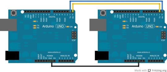
This article shows how to use Arduino serial ports when additional serial ports are needed for a project.
Arduino Serial Ports Available
The serial port for programming the Arduino mentioned above is a hardware serial port. The microcontroller on the Arduino board has a hardware serial port built-in, so that after the port has been initialized by software, a byte sent to the port will be sent out serially by the hardware.
The Arduino Uno has only one hardware serial port because the microcontroller used on the Uno has only one built-in serial port. The Arduino MEGA 2560 and Arduino Due both have 3 extra hardware serial ports.
Serial Port Technical Details
The hardware serial ports referred to here are UART (Universal Asynchronous Receiver Transmitter) ports. They may be referred to as USART (Universal Synchronous Asynchronous Receiver Transmitter) ports in the microcontroller documentation if they are configurable in both synchronous and asynchronous modes.
Arduino Uno Serial Port
This image shows the only serial port available on the Arduino Uno highlighted in red. The port connects through a USB chip to the USB device port.
Arduino MEGA 2560 and Due
Both the MEGA 2560 and Due have 4 serial ports in total. One that connects through a USB port chip to the USB device port on the board and three extra serial ports that connect to pins on one of the pin headers of the board.
Arduino Due Serial Ports
Pins 0 and 1 of the Due and MEGA connect serial port 0 through to the USB device port so that these Arduino boards are compatible with the pin numbering of the Uno and therefore with Arduino shields.
The extra serial ports are ports 1 to 3 with each port having a transmit and receive pin.
It is important to be aware that the MEGA 2560 serial port pins use 5V voltage levels, but the Due uses 3.3V voltage levels.
How to Use Additional Arduino Serial Ports
An extra serial port can be used on an Arduino Uno, but must be simulated in software by using the SoftwareSerial library.
Arduino Uno
The following code is taken from the article on serial communications with the GT-511C3 fingerprint scanner which connects the fingerprint scanner to a software serial port on an Arduino Uno.
To use the software serial port, first the header file for the software serial library must be included.
Next create the software serial port, selecting the Arduino pins to use for receive (RX) and transmit (TX). Here pin 8 has been set as the receive pin and pin 7 as the transmit pin.
The software serial port had been given the name gtSerial which will be used in the sketch to refer to this serial port.
The port can now be checked for incoming data.
If data is available, it can be read from the port.
Data bytes can also be sent on the port.
How to Use Additional Serial Ports on the Arduino MEGA 2560 and Due
The additional hardware ports on the Arduino MEGA 2560 and Due can be used in the same way as the main USB serial port is used in sketches, only changing the name of the port. The USB serial port, or serial port 0 is referred to as Serial in sketches. To use serial port 1, the name changes to Serial1. Serial ports 2 and 3 are referred to as Serial2 and Serial3.
This sketch shows serial port 3 being used which transmits on pin 14 of the MEGA or Due and receives on pin 15.
The additional serial ports are immediately available in the sketch without having to include any libraries.
Serial port 3 must first be initialized to the desired baud rate.
The port can be checked for incoming data.
If a byte has arrived on the serial port, it can be read.
A byte can be written to the serial port.
Arduino Serial Port Resources
Arduino Website References for Software and Hardware
Software serial library Arduino reference.
Serial port library Arduino reference for hardware ports.
Arduino Uno — hardware reference.
Arduino Mega 2560 — hardware reference.
Arduino Due — hardware reference.
Projects, Articles and Tutorials
Arduino Functions List
Using the Arduino serial port and serial monitor window.
Getting serial input from the serial monitor window.
Arduino serial thermometer breadboard project.
Measuring voltage with Arduino — displays voltage in the serial monitor window.
Reading an analog value with Arduino.
Finding the Arduino serial USB port number on a PC using Processing.
Serial communications with a fingerprint scanner using Arduino and Processing.
0 notes
Text
Servo
- Parts used
UNO R3
Servo motor SG90
3x wires
Video:
youtube
Circuit diagram:

Code:
#include <Servo.h>
Servo myservo; int pos = 0;
void setup() { myservo.attach(9); }
void loop() { for (pos = 0; pos <= 180; pos += 1) { // in steps of 1 degree myservo.write(pos); delay(15); }
for (pos = 180; pos >= 0; pos -= 1) { myservo.write(pos); delay(15); } }
Explanation: The code includes the library servo.h, which allows the assignment of a servo to a pin and then that is controlled by sending pulses from the UNO to the servo.
Troubleshooting required: Understanding how a digital servo works is a must for this project, whilst the accompanying documentation was sufficient in explaining how they worked, it took me a little bit longer to understand how the code worked, i had to go back and look through it a few times before I was confident with it. Also making sure that the Arduino has a sufficient power supply to the servo, or using a separate power supply.
Evaluation: Probably one of the simpler but cool projects we did since actually moving something in the real world after entering in the code felt kind of awesome, the introduction to servos was interesting, the way i would suggest improving this is either using a stronger servo or using a separate power supply.
Difficulties others may encounter: Making sure the correct pin is initialised and knowing which way the servo is going to turn is a help and making sure that the Arduino has a sufficient power supply to the servo, or using a separate power supply.
0 notes
Text
Fire foam balls from this Arduino-based wireless Nerf sentry turret
Named the grand prize winner of Instructables’ Arduino Contest, a maker known as otjones99 has created an interesting take on the classic Nerf sentry turret design by building one that uses an FPV headset to see and fire at targets. The turret consists of a turntable for moving the assembly side-to-side, along with a simple servo mechanism for tilting the end up and down. Small foam balls are ejected from the turret by a pair of counter-rotating wheels that were taken from a couple of blower style fans.
In order to control the rotating base and the loading/tilting mechanisms, a single Arduino Uno was positioned at the bottom and connected to the two servos and the ESCs for the spinning wheels. Commands for actuating the sentry are received by the onboard nRF24L01 wireless module that sends them to the Uno over the SPI bus.
The user is able to move the sentry turret by turning a pair of potentiometers within a Logitech joystick attached to an Arduino Nano. There is also a set of momentary pushbuttons to switch the safety on or off and to launch. This data gets transmitted from the nRF24L01 module onboard to the other one on the turret.
This project is a really fun way to explore both first-person control and topics in wireless communication. To read more about the sentry turret, you can check out otjones99’s well-documented tutorial here.
youtube
The post Fire foam balls from this Arduino-based wireless Nerf sentry turret appeared first on Arduino Blog.
Fire foam balls from this Arduino-based wireless Nerf sentry turret was originally published on PlanetArduino
0 notes
Text
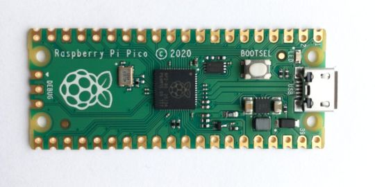
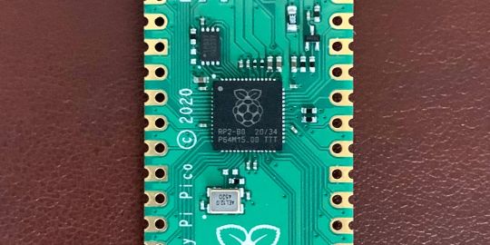
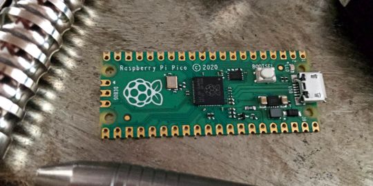
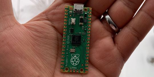
A Peek at the Pico, Raspberry Pi's Newest Petite Powerhouse
Raspberry Pi Pico
8.80 / 10
Read Reviews
Read More Reviews
Read More Reviews
Read More Reviews
Read More Reviews
Read More Reviews


Shop Now
Meet the new Raspberry Pi Pico; a tiny microcontroller filled with big possibilities.
Specifications
Brand: Raspberry Pi
CPU: Dual-core 133Mhz ARM
Memory: 264Kb
Ports: microUSB
Pros
Powerful ARM Processor
Micro-USB Connectivity
Breadboard Mountable
Easy-To-Use Interface
Absolutely Adorable
Inexpensive
Cons
No Wi-Fi or Bluetooth connectivity
No Header Pins
I/O Port Labelling on One Side Only
No USB-C Connectivity
Buy This Product
Raspberry Pi Pico other
Shop
// Bottom var galleryThumbs1 = new Swiper('.gallery-thumbs-1', { spaceBetween: 10, slidesPerView: 10, freeMode: true, watchSlidesVisibility: true, watchSlidesProgress: true, centerInsufficientSlides: true, allowTouchMove: false, preventClicks: false, breakpoints: { 1024: { slidesPerView: 6, } }, }); // Top var galleryTop1 = new Swiper('.gallery-top-1', { spaceBetween: 10, allowTouchMove: false, loop: true, preventClicks: false, breakpoints: { 1024: { allowTouchMove: true, } }, navigation: { nextEl: '.swiper-button-next', prevEl: '.swiper-button-prev', }, thumbs: { swiper: galleryThumbs1 } });
We’ve managed to get our hands on the coveted Raspberry Pi Pico. Today, we’re going to be looking at some of the most important features and putting it toe-to-toe with some of the biggest names in small electronics.
We’ll be showing you what the Pico can do, and we’ll get you started with MicroPython, one of Pico’s supported programming languages. We’ll even offer up some code to try in case you decide to buy a Pico of your own.
What Is a Raspberry Pi Pico?
Raspberry Pi Pico is a new budget microcontroller designed by Raspberry Pi. It’s a tiny computer built around a single chip, with onboard memory, and programmable in/out ports. Historically, microcontrollers are used in a variety of devices from medical implants to power tools. If you have an electronic device sitting in your vicinity, there’s a good chance that there’s a microcontroller inside of it.
Key Features of the Pico
The Pico is built around the RP2040 microcontroller chip, which was designed by Raspberry Pi UK. It’s a Dual-Core ARM processor with a flexible clock that can run up to 133 MHz. The Pico also supports 1.8-5.5 DC input voltage, has a micro-USB input port, and an onboard temperature sensor.
Flanking the chip on all sides are a series of castellations that allow easy soldering to a Veroboard or breadboard. This dual in-line package (DIP) style form factor is stackable, and can also be used in carrier board applications.
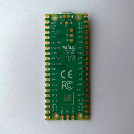
Technical Specifications
21 mm x 51 mm
264kb on-chip RAM
2 MB on-board QSPI flash
2 UART
26 GPIO
2 SPI controllers
2 ISC controllers
16 PWM channels
Accelerated integer and floating-point libraries
3-pin ARM Serial Wire Debug (SWD) port
What’s So Special About the Pi Pico?
The Pi Pico is a different kind of microcontroller. It’s Raspberry Pi’s first, and it features ARM technology in its RP2040 silicon chip. Many technology companies are embracing silicon ARM chips, with major manufacturers like Apple leading the charge.
The punchy little Pico packs a staggering 26 multifunction general purpose input/output (GPIO) ports, including 3 that are analog. Alongside these ports are 8 programmable input/output (PIO) ports. Compare this to other microcontrollers like the Arduino Nano, and the Pico packs roughly 18% more GPIO capability.
The most considerable difference between the Pico and its competitors, however, is the $4 price tag. Low cost is the main selling point of this unique offering.
At launch, many online retailers sold out of the device due to the interest and Raspberry Pi’s favorable reputation. By setting the price so low, the Pico opens the door for a new class of high-powered, budget microcontrollers.
There are many potential applications for the new Pico. With its onboard temperature sensor, the device is an obvious choice for IoT projects.
One talented retro gaming enthusiast even used a Pico to build a gaming console with full VGA video support.
youtube
This means that makers who have been curious about Raspberry Pi, or microcontrollers in general, now have the ability to experiment for less than the price of a fancy cup of coffee.
Related: The Raspberry Pi Comes of Age With the Pi 400 Desktop
The Raspberry Pi Pico Processor
The RP2040 ARM chip is an interesting choice for the Pico. At 133MHz, the chip is capable of leaving more expensive boards, like the Arduino Uno, in the dust.
Using ARM processors seems to be an emerging trend in the world of microcontrollers. In addition to Raspberry Pi, both Sparkfun and Adafruit also offer boards with similar ARM technology.
The industry-wide switch was made for a single reason—speed. ARM processors give a considerable boost over standard Atmel chips. In a board this size, using an ARM processor is like dropping a fully kitted Porsche engine into a Volkswagen. On the other hand, many microcontrollers don’t require that much processing speed. Yet.
Ramping up performance means that makers who want to push the limits of the Pico will have an abundance of power to do so.
The I/O Ports
The GPIO ports on the Pi Pico feature several interesting functions for common uses such as operating a screen, running lighting, or incorporating servos/relays. Some functions of the GPIO are available on all ports, and some only work for specific uses. GPIO 25, for example, controls the Pico’s onboard LED, and GPIO 23 controls the onboard SMPS Power Save feature.
The Pico also has both VSYS (1.8V — 5.5V) and VBUS (5V when connected to USB) ports, which are designed to deliver current to the RP2040 and its GPIO. This means that powering the Pico can be done with or without the use of the onboard micro-USB.
A full list of the I/O ports is available on Raspberry Pi’s website in its complete Pico documentation.
Pico vs. Arduino vs. Others
One question on the minds of many makers is whether or not the Raspberry Pi Pico is better than Arduino?
That depends. Pound-for-pound, higher-end Arduino boards like the Portenta H7 make the Pico look like a toy. However, the steep cost for a board of that caliber might be a tough pill for the microcontroller hobbyist to swallow. That's why the smaller price tag on the Pico makes it a win for makers who enjoy low-risk experimentation.
Along with minimal cost, the Raspberry Pi jams an extensive feature set into the Pico, comparable to boards like the Teensy LC, and the ESP32. But neither of these competitors manage to challenge the budget-friendly Pico on price.
That's what makes the Pico such a fantastic value, and a great choice for hobbyists and power users alike.
The Pi Pico: What’s Not To Love?
Unfortunately, to drive the price of the Pico down, Raspberry Pi had to make a few compromises. The most notable of which is the lack of an onboard radio module. Neither Bluetooth nor Wi-Fi is supported without add-ons.
The Wi-Fi limitation can be eliminated by adding a module like the ESP-01. Bluetooth support may prove a bit more challenging. If you need an all-in-one solution for your products, you’re better off skipping the Pico, and spending a little extra for something like the Pi Zero W, or ESP32.
Additionally, many early adopters are complaining about the lack of GPIO labeling on the top of the board. Raspberry Pi provides an extensive amount of documentation on its website to address this, but pointing-and-clicking, or thumbing through paperwork when you have a hot soldering iron in your hands isn’t often desirable.
Lastly, the lack of I/O pin headers is something of an issue for some, as it means less convenience when swapping I/O components. This minor annoyance can be solved via the use of leads, soldering the component wiring directly to the Pico, or using a breadboard.
If you’ve been using microcontrollers or small electronics for any period of time, then an unpopulated board is most likely a non-issue. Of course, you could also add your own pin headers if you plan on regular experimentation with different external components.
The final rub with the Pico is the micro-USB port. With many other microcontrollers like the Portenta H7 moving toward USB-C, Raspberry Pi's micro-USB port seems dated.
Logically however, the decision to use micro-USB makes sense. It was done by Raspberry Pi to keep costs as low as possible, and to keep interface capability almost universal. Everyone we know has at least a few micro-USB cables tucked away somewhere in their homes.
However, with future versions, a USB-C interface would be a nice addition to an already spectacular package.
Related: A Beginners Guide To Breadboarding With Raspberry Pi
Programming the Raspberry Pi Pico
Interfacing with the Pi Pico can be done via C/C++, or via MicroPython in the Read-Eval-Print-Loop or REPL (pronounced “Reh-pul”). The REPL is essentially a command line interface that runs line-by-line code in a loop.
In order to access the REPL, you’ll need to install MicroPython onto the Pico. This process is simple and only involves four steps.
Installing MicroPython
Download MicroPython for Raspberry Pi Pico from the Raspberry Pi Website
Connect the Pico to your computer via micro-USB while holding the BOOTSEL button
Wait for the Pico to appear as an external drive
Copy the MicroPython file to the Pi Pico, and it will automatically reboot
You can access the REPL in a number of ways. We used the screen command in a macOS terminal window to access the serial bus connected to the Pico. To accomplish this with Terminal, you’ll first open a new terminal window, then type ls /dev/tty*
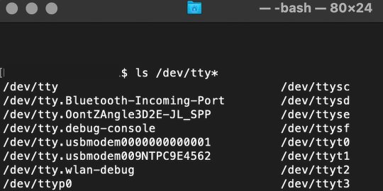
From there, find the port where the Pico is connected. It should be labeled something like /dev/tty.usbmodem0000000000001. Then run the command:
screen /dev/tty.usbmodem0000000000001
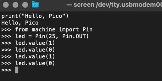
Your cursor should change. Hit Return and the cursor will change again to >>>.
In the image below we've included the classic Hello World (Hello, Pico) command-line program in the REPL, along with a few lines of code that will turn the Pico's LED on and off. Feel free to try them yourself.
For more information, we recommend you invest in the official starter guide to MicroPython that Raspberry Pi has published on their website.
Download: MicroPython for Raspberry Pi Pico (free)
Using the Raspberry Pi Pico With Thonny
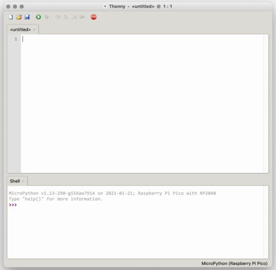
If you’re looking for a more proper coding environment, the Raspberry Pi Pico will also allow access to the REPL with Thonny. To enable this feature, first download and install Thonny. Once installed, connect your Pi Pico. Open Thonny and you'll see information indicating your Pico is connected in the Shell.
At the bottom right of the screen, you should see a version of Python. Click this version and select MicroPython (Raspberry Pi Pico) from the drop-down menu.
Now you can type commands into the Shell, or you can use Thonny’s editor to write or import multiple lines of code.
The abundance of interface possibilities make the Raspberry Pi Pico easy to program. For those who are familiar with MicroPython, this should be nothing new. For beginners, however, Thonny provides a powerful interface and debugger to get started with programming.
Download: Thonny (Free) Windows | Mac
Should I Buy the Raspberry Pi Pico?
The Raspberry Pi Pico is a powerful budget board that is perfect for hobbyists, or makers just starting out with microcontrollers. The documentation, low cost, and wide range of possibilities for the Pico also make it a great choice for seasoned small electronics wizards. If you’re a DIYer who loves to tinker, or you just want to challenge yourself to a weekend project, then you’ll love playing with the Pico.
On the other hand, if you don't have one or more projects in mind that need a microcontroller, then this board is probably not for you. Also, if your project needs Wi-Fi connectivity or Bluetooth, then the Pico won’t scratch that itch. And finally, for users who aren’t comfortable learning MicroPython, or exploring C/C++, the Pico isn't ideal. And remember: this Raspberry Pi is not like the others. It will not run a full Linux operating system.
But, if you dream in Python, or if you love the smell of solder, then you won't regret grabbing this tiny powerhouse. Most of all, if the sight of the sports-car-sleek RP2040 gets your creative gears turning, then we think you’ll really benefit from picking up the Pico.
Serving up Several Sweet Possibilities
While it isn’t perfect, the Raspberry Pi Pico is a strong entry into the world of microcontrollers. The reputation that Raspberry Pi has built for quality electronic components at a relatively low price extends to the Pico.
It’s everything a Raspberry Pi should be: small, sweet, and superb. It’s beautifully designed, and extremely inexpensive. But the best part isn’t the looks or the low cost.
The best part about this small wonder is picking it up, and holding it in your hands. It's feeling the tug of electronic inspiration. It's realizing just how powerful the Pico is, and what it means for microcontrollers going forward.
And truthfully, we think it's amazing that something as small as the Pico can offer so many unique possibilities.
A Peek at the Pico, Raspberry Pi's Newest Petite Powerhouse published first on http://droneseco.tumblr.com/
0 notes
Text
Machine for Autonomous Growth and Moisture


Gitlab: https://gitlab.doc.gold.ac.uk/jdeve003/final-project-2020 Video documentation: https://vimeo.com/431051447 Livestream: https://www.youtube.com/watch?v=kL2voDahzyk
Adapted Project
Project description
“Machine for Autonomous Growth and Moisture” is a sculpture, a speculative “body” that materially, sensorially and conceptually suggests what kind of assemblages of life might exist in a world defined by hybridity and interconnectedness. It is situated in an imaginary, post-apocalyptic and possibly post-human future in which digital code meets biological hardware and spawning sprouts meet electrical waste. The sculpture is a landscape of both independent objects as well as a connected system, the spraying influences the sprouts, the sprouts influence the spraying and the audio gives voice to the sprouts, signalling their fluctuating mood to the surroundings.
The project gestures towards a post-capitalocene planet, a term suggested by environmental historian Jason Moore as a subversion of the term “anthropocene” which puts the focus on capitalism as a system rather than individual human influence on the environment. “Capitalism made this mess, and this mess will ruin capitalism” (Simon, 2019). In this new reality the sculpture forms a self-generating system that plays with the aesthetic and possibilities of survivalist methods of open source autonomy and DIY, makeshift building structures. It is functional, but it is also semiotic. It contemplates what space the digital can inherit in these forms of assemblages, as the mega tech corporations have disappeared the code will live on - but in what form and through what hardware? What are the forms of digital survivalism?
A livestream of the project was streaming for the duration of 3 hours on the 18th of July 2020. Although a stream was not originally a planned part of the project, it was an adaptation that gave the project a digital space and the possibility for an audience to follow the life of the sculpture for a longer amount of time, a sort of “slow” way to experience an art piece where one can return many times to a piece without the restraints of the gallery space. This was inspired by projects such as Brent Watanabe’s “San Andreas Streaming Deer Cam” (Watanabe 2016) in which a stream is set up of a modified deer in the game GTA V, following the deers shenanigans through the fictional city of San Andreas. Similar to this is also the tv-program “Den stora älgvandringen” (The Great Moose Walk) streamed on Swedish public television, a four week livestreamed program documenting the yearly migration of moose (SVT, 2020). These types of “slow-tv” streams often have a hypnotic quality to them, making the viewer return several times to see what has changed since last, the stream creating a peep hole into a different world.
In a gallery space, the piece would act as part sculpture, part continuous and durational performance piece, evolving and changing throughout the exhibition period. Ideally it would be installed in a quiet space to give room for the sonic scape created by the audio and the sound of the spray bottles, and to leave space and a calm atmosphere for the audience to watch the piece for longer periods of time. The lighting of the piece would come from LED growth lights, which give a soft purple glow, as well as discreet spotlight directed towards the installation to give it an evenly distributed light without dark shadows. As the piece aims to be as self-sufficient as possible it would not be relying too much on natural lighting, the lights would instead be included in the installation as a part of the system of the machine. The livestreaming element would not necessarily be included in the piece’s gallery-version, the livestream is rather a moment in itself, separate from the gallery exhibition.
Audience engagement
I see this piece as an active process, and it is a process I am hoping the audience wants to be involved with. As it is durational, it’s main “function” - the spraying bottles - are not continuous, but dependent on the moisture levels of its biological component. Thus, the audience will all experience different parts of the piece depending on what stage of the process the machine is in during that moment. It is my hope this would create a curiosity to experience and understand the processes of the piece and to reflect on the system that makes the installation as a whole - how it is put together, and the implications of what the collaboration between its components might mean. The fact that it is durational turns it into something I hope members of the audience will return to, and that each encounter with the work will be a new experience.
A lot of my work moves in the boundaries of what might arise as technological components and biology converges, and it is my intent that the audience will get a sense of the cooperation and symbiosis I imagine in the piece, which will help to expand the way we imagine the unknown aspects of the intimidating future.
The piece is not interactive in the way we normally talk about interactivity in computational arts, and it is something I reflected on throughout the process of making this work. Interactivity can be a powerful tool, but with this project I wanted to point attention to interactions that are devoid of human contact and influence. The piece hints to human intervention, we often perceive the concept of “machines” as human-made, but it has been assembled to facilitate a process that focuses on communication between components often seen as distant from each other - and to pay attention to the multiplicity of realities and worlds that might / might not exist.
Although there is no direct human interaction with the sculpture, it facilitates sensory experiences. The spraying of the water from the bottles makes the floor damp, and one can feel the thin mist if standing close to the piece. The wheatgrass growing in the hanging baskets give of a slight smell, and there’s a humming coming from the power supply. As the spraying is dictated by the moisture in the grass, there is an element of unpredictability when getting close to the piece, the audio coming from the small speaker indicates the state of the growing wheatgrass sprouts, but only one who is thoroughly dedicated to listening and experiencing the machine would be able to predict the sprays. Maybe this can contribute to a speculation regarding who or what might assemble such a machine, in the imagined future suggested.
Creative process
The idea for this work largely stemmed from the research that came from writing my dissertation, which focuses on practices of survivalism and DIY self sufficiency as well as autonomous zones. I believe there is a radical potential in imagining “the end of the world”, to be bold in our imaginations of reorganisation and collectivity. In this process I have been looking into the work of the duo Queer Nature, an educational and social sculpture project that focuses on place-based skills with awareness of post-industrial, globalized and ecocidal contexts (Queer Nature, 2020). Their work has influenced the way I think about my own practice and the context I want to situate my artworks - as parts of an effort to think about a sustainable future by not being afraid of imagining the collapse of our current reality.
This is echoed in the writing of Alexis Pauline Gumbs and her book “M Archive: After the End of the World”. It documents the afterlife of the human-created climate crisis at a point where Earth has gone through several stages of freezing, flooding, torching heat and sulfuric contamination. It is narrated in second person by someone who has survived. Through the text she takes on antiblackness, environmental crisis and capitalism and explores how Black feminist theory is already after the end of the world ( for many the collapse has already happened.) (Gumbs, 2018).
Aesthetically I’ve been inspired by the work of Phoebe Washburn who’s dubbed her installations “spontaneous architecture” and the haphazard, precarious appeal in her installations is something I wanted to mirror in the process of building my structure. Her installation “It makes for my Billionaire Status” (Washburn, 2005) inspired the assembly and aesthetics of my own work as I think it combines a makeshift process with biological elements in an effective way. Additionally I’ve also been looking at the structures built in the ZAD (Zone to Defend), an autonomous zone in France. The buildings in the area serve many purposes, and are often both living quarters as well as watchtowers in preparation of eviction by police. Various amenities and agricultural installations are built to sustain their continuous occupation of the land - a form of functionality and anti-capitalist resistance that informs a beautiful sculpturality.


Phoebe Washburn “It makes for my Billionaire Status” (2005)


Images from the ZAD (2016)
To execute the functionality of the project I researched different platforms, Arduino is something I have experience of working with before, and it is an effective tool for the movement of the servos and the moisture sensor I wanted to use for the project. I looked into a few different ways of making a moisture sensor, and first tried to buy a ready made sensor. It turned out to give quite inaccurate readings and was not very reliable. So instead, I researched how to make my own sensor and eventually ended up using a tutorial from Instructables.com. It uses two nails as conductors, one which is connected to Analog Pin 0 on the Arduino Uno, and one which is connected to 5V. Through this, it calculates the resistance in between the two probes. This turned to give a much more accurate reading. (Parth2k, no date).
I also looked into using Raspberry Pi as a platform for running the project as a whole. My goal was to make the sculpture run as independently as possible, and to require little to no set up. Unfortunately, due to the unforeseen event of campus closing, using Raspberry Pi was not something I had the means to do after having traveled back home as many components were missing for me to be able to do the set up correctly.
In terms of the audio I mainly researched two platforms, Openframeworks and Max MSP. I wanted to set up communication from the Arduino to the platform of choice, and use the serial input from the moisture sensor to control the audio output. I have previous experience of setting up Arduino with Openframeworks by using ofSerial and ofArduino, but found it to not be very user friendly when it came to audio. It does have some audio libraries such as ofx Maximillian, but Max MSP felt like a better choice for me, as I through my research found it also can read serial communication from the Arduino. To set up this communication I looked mainly at the tutorial “Serial Arduino Live Data” (Programming for People, 2016). It uses an oscillator to give the sensor its audio output. I contemplated using samples for the audio instead of the oscillator, the sonic scape of the installation had to reflect the narrative I imagined. In the end, I decided that I found the audio from the oscillator to work well with the aesthetic of the piece as well with what I wanted to communicate, as it is a clear sound that quickly changes with the sensor, and gives it a simple, monotone digital feel, like if it is a calculating computer. The audio in the installation is connected through an old stripped down speaker which doesn’t allow for a very loud volume, something that requires the audience to move closer to the piece to get a clear sense of the sound.


(Above are screenshots of the code from the Arduino, and from my Max MSP patch)
The closure of campus made me have to adapt the project to my new situation. I was able to travel back home to my parents, and am lucky that they have tools and space that made me able to build something quite close to what I imagine the physical installation to be. I used all scrap material for the build and an old bedside table for the base - I wanted the look and feel of the piece to be DIY, as it is quite literally DIY, but also because this is the theme I am currently working with and it was thus important that this was reflected in the way it was built. The piece has small shelves cut out from MDF which have been spray painted in a pale olive green for the spray bottles to stand on. At the very top a seashell is placed on a shelf. Seashells are often used as symbols for protection, life and fertility and are acting as an amulet of sorts, protecting the sculpture. The installation is an assemblage of items and ornaments, each chosen to create a connection to the narrative created for the work. On one of the arms holding up the hanging basket is an orange insulated water bottle, a water supply for the spray bottles as well as a common tool used when camping or hiking.
The main re-planning done for the project has been through adapting to the loss of the materials and tools available through the university. I do feel like the code I’ve created for the installation is what I had in mind, but the assembly of the different technological components are less sophisticated than what I imagined. For example, the servos were originally planned to be powered through batteries, in order to make the installation less dependent on electrical outlets. Max MSP is running through my laptop in the installation, which is also something I had to adapt to as it was originally planned to be run through Raspberry Pi. In general I feel as if I've managed to execute the main functionality I originally planned for the piece, but the solutions for the set up have had to become less self-contained than what I was hoping to make, as well as less practical. This is something I am hoping to continue to work on, as I see the installation to work as a self contained system and it would be great to incorporate things that could facilitate this more, such as solar power driven batteries and an automated water supply for the bottles.
Final iteration
This project is a sculpture with spray bottles attached to servos, the servos are connected to a soil moisture sensor run through Arduino uno. The servos are told to spray everytime time the moisture level of the wheatgrass growing in the installation reaches under a threshold set out in the code of the Arduino, and to keep spraying until the moisture level is above this threshold. The moisture sensor is made of two nails attached to the Arduino through wires, measuring the resistance in between the two nails. The sprouting process of the wheatgrass was initiated 8-9 days before the planned set up of the piece. The moisture sensor is also connected to Max MSP that reworks the signal from the sensor into audio, which is put through a small speaker at the top of the sculpture. Finally, the building of the piece was done through collected scrap material and an old bedside table. It is done in a makeshift way, gesturing to artists such as Phoebe Washburn, and the architecture of the ZAD.
References
Bwatanabe.com. 2016. Brent Watanabe : San Andreas Streaming Deer Cam, 2016;. [online] Available at: http://bwatanabe.com/GTA_V_WanderingDeer.html [Accessed 22 June 2020].
Gumbs, A., 2018. M Archive After The End Of The World.
Instructables.com. n.d. [online] Available at: https://www.instructables.com/id/DIY-SOIL-MOISTURE-SENSOR-CHEAP-YET-ACCURATE-/ [Accessed 22 June 2020].
Queer Nature. 2020. Queer Nature. [online] Available at: https://www.queernature.org/ [Accessed 22 June 2020].
Simon, M., 2019. Enter The Capitalocene: How Climate Change Will Ruin Capitalism. [online] Wired. Available at: https://www.wired.com/story/capitalocene/ [Accessed 22 June 2020].
SVT Play. 2020. Den Stora Älgvandringen. [online] Available at: https://www.svtplay.se/video/27031309/den-stora-algvandringen/den-stora-algvandringen-hojdpunkter-sasong-2-avsnitt-1?info=visa&start=auto [Accessed 22 June 2020].
Youtube. 2016. Max MSP Request: Serial Arduino Live Data Stream. [online] Available at: https://www.youtube.com/watch?v=tOPObpGnrIA [Accessed 22 June 2020].
Zachfeuer.com. 2005. Phoebe Washburn: It Makes For My Billionaire Status | Zach Feuer. [online] Available at: http://www.zachfeuer.com/exhibitions/phoebe-washburn-it-makes-for-my-billionaire-status/ [Accessed 22 June 2020].
1 note
·
View note
Text
Weather Monitoring System Using Internet of Things - Juniper publishers
Journal of Trends in Technical and Scientific Research
Abstract
In this research, a foundation is set for an efficient solution for tracking the weather conditions of a specific location and making the information available anywhere in the world. The technological advances behind this is Internet of Things (IoT), which is an efficient and effective solution for linking the things to the web and to connect the entire world of things in a network. Here things could be like electronic gadgets, sensors, and automotive electronic devices. The system functions with tracking and monitoring environmental circumstances such as temperature, relative humidity, light intensity, pressure and quantity of rainfall with sensors and whenever these scores exceed a selected threshold limit for each an e-mail, an SMS alerts the appliance owner to take the required steps
Keywords: Smart Environment; Internet of Things Weather Monitoring System Cloud
Introduction
Present technological innovations focus primarily on managing and tracking various operations. To achieve human needs, these are increasingly emerging. To monitor and evaluate the circumstances in case of exceeding the prescribed level of parameters (e.g. noise, gas and radiation levels), an effective environmental monitoring system is needed. When objects such as environment embedded with sensor devices, microcontroller and multiple software applications become an environment of self-protection and self-monitoring, it is also called a smart environment. In such an environment the alarm or LED alerts automatically occur when some incident happens. The impacts on livestock, crops and humans due to the environmental modifications can be tracked and regulated by a smart monitoring system for the environment. By making the environment interactive with other objectives by using embedded intelligence, this is one of the applications that targets smart environment. Human needs are dependent on the type of information collected by the sensor devices, different kinds of monitoring systems. The two categories to which applications are categorized are based on event detection and spatial process estimation. Initially, sensor systems are implemented in the environment to detect parameters (e.g., temperature, humidity, pressure, LDR, noise, CO and radiation levels, etc.) while acquiring, computing and controlling information (e.g., noise and gas levels variations in the specified levels).Sensor devices are positioned at various places to gather information to predict the behavior of a specific area of interest. Here Internet of Things (IoT) is the concept of linking all the sensors to the internet [1]. The primary purpose of this document is to develop and execute an effective monitoring system whereby the necessary parameters are remotely controlled using the internet and the information collected from the sensors are stored in the cloud and analyzed there and then an email, an SMS alerts whenever the threshold limit exceeds [2].
Materials and Methods
Problem Statement
The satellite weather reporting system provides the current condition that does not give the exact location condition. The drawbacks are in conventional approach where the devices are costly and have no visualization of information. There is no such automatic tool to offer the alert signal in case of any abnormalities, so it is difficult to regulate this abnormality
Proposed Model
Weather conditions are tracked in the home’s external environment or any buildings and information are transferred to the cloud server. The benefits will be that this system will manually transmit the real-time environment information. It is possible to view the information in any part of the world. This application isto monitor and update the condition of the surroundings regularly. Conditions of the environment can be tracked by gathering the data from the sensors and deposited in the cloud and analyzed there and then an email, an SMS alerts if the situation of the environment becomes abnormal.
Environment Monitoring System
An IOT application is used to monitor the environment that helps monitor the environmental condition of any local area or a surrounding area, and with the help of the internet everyone can view the condition. This application is more efficient, quicker in offering conditions for the environment [3]. It enables people or government to take remedial action if the environmental condition becomes abnormal. Environmental condition monitoring system offers a technique for verifying the condition and changes occurs over the surrounding. In this system we use Arduino, sound sensor, gas sensor, temperature sensor, moisture sensor, pressure sensor, IOT module. The humidity and temperature sensor will track climate change and provide information. It is helpful for agriculture [4]. To monitor pollution over the atmosphere, the gas and sound sensor are used. Currently, pollution from air and noise makes the environment more susceptible. Using this module, we can identify the polluted area and expressly create people’s consciousness for living in the pollution. Changes in the climate system cannot be accurately defined and sometimes accidentally defined, but with the help of an IOT module we can characterize more approximate changes in an environment and update them in the cloud. This system uses many modules as follows:
Sensor Module:
The sensor network is linked to a hefty amount of small sensor nodes that can be used as an effective tool for collecting information for different applications under different situations [5,6]. Different sensors are integrated into this study that has its distinctive way of collecting information from the surroundings. An integrated circuit sensor (LM35) used to evaluate temperature with an electrical output proportional to the temperature (in oC). If the temperature goes up, the fan is going on and vice versa. The factor of scale is .01V / oC. The LM35 requires no external calibration or trimming and retains a +/-0.4oC accuracy at room temperature and +/-0.8oC over 0 oC to+ 100 oC range.
System utilizes moisture sensors DHT11. It provides outstanding quality, quick response, capacity to prevent interference, and cost-effectiveness. On the calibration of humidity, this sensor is highly precise.
MQ-6 gas sensor’s sensitive material is SnO, which has lower conductivity in clean air. The MQ-6 gas sensor is highly sensitive to Propane, Butane and LPG, as well as natural gas response. The Sensor could be used to detect various fuel gases, particularly methane; it is appropriate for separate applications at a low price.
The sound sensor module offers a straight-forward sound monitoring technique and is generally used for sound power detectiondetection. This module can be used for apps for safety and tracking. Its precision for comfort of use can be readily adapted.
The BMP180 is an I2C standard device and a pressure sensor. It’s a 4-pin tool, i.e., SDA, SCL, VIN, GND. The connection between Vin and GND is 3.3V and GND. SDA connects to the nodemcu D2 pin and SCL connects to the nodemcu D3 pin.
Power Module:
The Power for the system can be provided via the adapter or the USB. Use the USB cable or an external power supply to power the Arduino board. Source of power can be selected automatically.
Controller Module:
This implementation is controlled by Arduino UNO. The Arduino board transforms to digital data the analog data produced by the sensor. Arduino is generated to monitor or comprehend the environment or surroundings by receiving feedback from a variety of sensors and can impact its atmosphere by controlling lights, engines, and other actuators. The board’s microcontroller is programmed using the Arduino programming language and Arduino development environment. Arduino projects can be separated or when operating on a desktop they can interact with software.
IoT Module:
The IoT board is intended to satisfy a range of online application demands with different benefits that allow the embedded system designer to readily, rapidly and seamlessly add internet connectivity to their applications. The module’s UART update feature and webpage management make them excellent for online wireless applications like environmental sensors and information from moveable battery-operated wireless sensor network devices. Lumisense IoT board is designed with SIM900 GPRS modem for active internet connection so that it is equipped with a controller for processing all UART data based on GPRS online data.
Light Dependent Resistor (LDR):
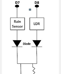
An LDR is a light-controlled variable resistor. The LDR’s strength is reduced by the increasing light intensity falling on it. It has an analog output that is an input to the nodemcu’s A0 pin.
Raindrop Module:
It is used for rain detection. It can also be used to measure rain intensity. It has both digital and analog output. This module analyses the moisture by means of analog output pin and gives a digital output when the moisture limit exceeds too much. The more water or less resistance implies the reduced voltage of the output. Whereas, the less water implies higher resistance, i.e, high output voltage on the analog pin. For instance, a totally dry board will result in five volts of module output. The module’s analog output is linked to the nodemcu’s A0 pin.
Working of the Analog Pin (A0):
The Nodemcu board has only 1 analog pin, but two analog output devices, viz, LDR and Raindrop module, are multiplexed to the A0 using two diodes in this project. The circuit of multiplexing is shown in Figure 1 below. Here the Raindrop Vcc sensor is connected to the nodemcu D7 and the LDR input is connected to the nodemcu D8. When D7 is high, D8 is low, making LDR off and module raindrop on. Thus,the raindrop sensor output reaches the nodemcu A0 through the diode. Similarly, when D8 is high and D7 is low, the LDR is on and the raindrop module is off creating a route for the LDR output to achieve the nodemcu A0 through the second diode.
Execution
Arduino is driven by a USB cable and the four sensors are linked to the Arduino board and the information collected from the sensors is stored in the cloud and analyzed there and then an email, an SMS alerts whenever the threshold limit exceeds. The IoT module is also linked to the Arduino board to receive feedback from the sensors and is driven by the adapter. The USB cable givespower to the Arduino board and then transfers information from Arduino board to the computer
Results
Once the sensor measures are downloaded to the cloud, the values are evaluated and then the threshold limit exceeds an e-mail, an SMS and a tweeter post are posted. Some findings of the study are as follows Figures 2 & 3.
Algorithm 1:Analog Pin Multiplexing Input: LDR D8, raindrop D7; Output: Analog pin A0 loop { if (digitalRead(D7) == HIGH) { A0=raindrop sensor value; digitalWrite(D7, LOW); } else if (digitalRead(D8) == HIGH) { A0=LDR value; digitalWrite (D8, LOW); } }
Algorithm 2:E-mail, SMS Input: temp, humidity, press, LDR, rain; Output: email, sms loop { temp=temperature value measured; humidity=humidity value measured; press=pressure value measured; LDR=light intensity measured; rain=rain value measured; if (temp && humidity && press && LDR && rain) { publish all the measured value to the cloud bluemixserial.println(temp); serial.println(humidity); serial.println(press); serial.println(LDR); serial.println(rain); } else { serial.println(” error! check the sensors.”); } if(temp>=40) { email=” The current temperature is” + temp; sms=” The current temperature is” + temp; } if(humidity>=50) { email=” The current humidity is” + humidity; sms=” The current humidity is” + humidity; } if(rain>=200) { email=” It’s raining outside. Bring your umbrella”; sms=” It’s raining outside. Bring your umbrella”; } if(LDR>=150) {post only once in a day { email=” Good Morning”; sms=” Good Morning”; } } }
Conclusion
This System monitors the changes happening over the environment and provides enough ways for the users to access the information from anywhere through cloud. The temperature and humidity sensor will monitor and gives the details about the changes happening over the climate. The gas and sound sensor are used for monitoring the pollution over environment. The Monitored condition will be updated in the cloud.
To Know More About Trends in Technical and ScientificResearch Please click on: https://juniperpublishers.com/ttsr/index.php
To Know More About Open Access Journals Please click on: https://juniperpublishers.com/index.php
#Juniper Publishers#Open Access Journals#Juniper publisher reviews#Peer review Journals#Scientific research
0 notes
Text
Witch Lights Work Diary, Monday; April 17, 2017
Last time, I had just done a full-scale test of the new Witch Lights harness, only to find that the voltage on the far end of the harness was 3.6 volts, too little for the cheap PIR sensors I was using to work properly. I had my hopes pinned on a new set of PIR sensors from SeeedStudio, which are rated to operate with 3-5 volts.
Last week, the new sensors arrived. The Witch Lights are still snaking down my house's stairwell and into the living room, so I took the time to hook up the new LED strips I had just soldered. And on turning the lights on… they browned out.
Great.
Slowly disconnecting and reconnecting each LED strip informed me that two of the four LED strips were bad somehow, and will need to be re-soldered. Somehow, both of them passed my QC testing, but still fail when they're hooked up to the actual harness. Fantastic. Spare LED strips were dragged out, and the offending strips set aside for further punishment investigation.
With LEDs hooked up and running, I was able to confirm the results from the earlier test: the 5 volt PIR motion sensor on the far end starts to go berserk within a few seconds of boot-up, and the lights animate constantly. OK, fair enough.
Time to do some surgery: I extracted the circuit board from the far-end motion sensor housing, and wired the new motion sensor into it. Moment of truth time. Turn the lights on, and…
It worked!
The new 3 volt motion sensors operate just fine in the 3.6 volts provided by the wiring harness, as advertised. The lights no longer trigger randomly, they trigger when a heat source (like my cats) walk by either motion sensor.
Hooray!
Of course, the new PIR sensors are a funny shape, and don't fit into the housings I designed around the original sensors. The next day, I spent a few hours in Solidworks with a pair of calipers, and designed a new housing. Some hours later, I had a new housing sitting on the bed of my original Makerbot Replicator. The new sensor press-fits into the housing. I installed the new housing with no problems, and now I have a fully-assembled, functional set of Witch Lights in my living room.
Which only left the bad LED strips. Grr. Fine, off we go to the workbench. Now, what worries me is, I have an Arduino Uno with a cable hookup that connects to the LED strips once the wireless cables are soldered on. That Uno runs a test animation on the strip. I've been operating under the assumption that if there's a short circuit, the LED strip will brown out when connected to the Uno, and the animation won't play. I used this to test all my strips after soldering.
Turns out, nope. The bad LED strips pass that test just fine. That does not give me the warm fuzzies, let me tell you. So the only real test of the LED strips is to connect them to a fully-deployed wiring harness. Which means I don't get the living room back any time soon.
Update Saturday; May 13, 2017
OK so since I started this entry, I have re-tested and re-worked the LED strips. I ran them continuously for about 16 hours (two battery charges worth), with no problems. That's as good a test as I can devise, so I have to sign off on them, but I'm still wary. This means the second, new set of Witch Lights is fully functional, with its own set of LEDs, ready to deploy. I put away the LED strips and coiled up the wiring harness. It will stay that way until I start reprogramming the Arduino with new code, hopefully in the next month or so.
That left the original Witch Lights, which had the same wiring flaw as the second strand; at critical points, ribbon cable was used as a shortcut to pulling wire. That led to them malfunctioning and constantly animating at Firefly 2016. My goal is to fix this issue before Firefly 2017, on July 4th.
I pulled the wiring harness out from under the Makerbot table, and slowly, laboriously took it apart into segments. It wasn't until I had the conduit laid out on the floor, ready for the wire pull, that I found out that I didn't have enough wire left. Damn. So that was a delay of a few days waiting for wire to come from Jameco.
Once the wire came, I wasted no time in pulling the power lines through the conduit, and started to reassemble the harness. That's a slow process because every time you connect conduit to one of the 3D-printed housings, you have to continuity test the wires to make sure that there's an unbroken chain from the Arduino and power source all the way through the wiring harness. Well, after connecting a long, complicated segment of the harness, the sensor wire failed the continuity test. Somewhere in the harness, a wire had come loose from a screw terminal.
Well, fuck.
I resigned myself to a long search. Then I found the loose wire in literally the first place I looked. OK, I was owed a break on this project I suppose. I accept the good luck. After reconnecting the wire, the harness passed continuity tests. I was able to reassemble the rest of the harness without issue. When it was fully assembled, I plugged in a battery and turned it on, then measured the voltage at the far end of the harness: 5.17 volts.
Huh.
And the debug LEDs on the Arduino tell me that the Witch Lights aren't animating constantly, but are only triggered when I activate the infrared motion sensors.
That's without LEDs hooked up. I don't know what their power drain will do to the voltage at the sensor on the far end. So next up is to do a full-scale deploy of the original Witch Lights, down the stairs and into the living room. My long-suffering wife will love that, but with any luck it will only be for a day, until I can confirm that the lights are working as designed.
After that, I can focus on the software improvements. Right now, if the lights are animating, the Arduino processor is locked up, and it can't respond to any further motion until the lights are done playing their animation. My hope is that, with the help of my friend Jim (a much more experienced programmer who knows C++ and can handle complicated object-oriented code), we can have animation code this summer that can display multiple sprites at once, and respond to motion while animating the lights at the same time.
Both the current and in-development code for the Witch Lights are on github, at https://github.com/jdimauro/witch-lights along with documentation of the build process.
And now, it's time to test the Witch Lights and see if the re-wiring was successful. Wish me luck.
3 notes
·
View notes
Text
Design And Construction Of A Password Based Circuit Breaker
Design And Construction Of A Password Based Circuit Breaker
This Research Work is on Design And Construction Of A Password Based Circuit Breaker
Format: Ms Word Document
Pages: 75
Price: N 3,000
Chapters: 1-5
Get the Complete Project
Title Page
Certification/Declaration
Approval Page
Dedication
Acknowledgement
Abstract
Table of content
Chapter 1
Introduction
1:1 Introduction
1:2 Background of the Study
1:3 Statements of Problems
1:4 Objectives of the…
View On WordPress
#arduino#Based#breaker#breaker password#circuit#documentation password#download password#ieee#of#paper password#password#pdf#pdf disadvantages#PHYSICS PROJECT TOPICS/MATERIALS#ppt password#PROJECT#Report#uno#Using#wikipedia password
0 notes