#i also need a microcontroller
Explore tagged Tumblr posts
Visit Tumblr Blog
Explore Tumblr blogs with no restrictions, modern design and the best experience.
Last Seen Tumblr Blogs


Fun Fact
Premium Tumblr themes are available from anywhere between $9 to $49.
Text
slowly putting together my plan to make a much much improved momo costume (i even have a spreadsheet and everything!!) but the amount of new things i'd have to buy is kind of scary tbh
#uhhhh me#the leds alone costs 30$ plus shipping...#i also need a microcontroller#a nano controller is $20 plus shipping#at least the programs are free thank god indie developers ilysm#ya ya i know ~$60-70 is not expensive by most people's standards#but i'm frugal ok#esp for this new territory. i don't know shit about computer science
2 notes
·
View notes
Text
having a day where i just want to give up on literally everything
#i dont want to read about grammar anymore. its boring as fuck and trying to understand how to form a proper sentence#just leads me down this endless void of accusatives and datives and infinitives and transitives and participates and particles and#i come out of it feeling like i learned nothing helpful. and like i have to study this entire other area of stuff#just to even have the *potential* to learn how not to sound like an idiot when i form sentences#i dont want to constantly look up the 73 conjugates every verb has either (and then not be able to find the correct one because i#need to have a master's degree in grammar to understand which one to use!)#I'm also dead tired of this circuits course. All it's done is put some sense into me and convinced me to revert back to my focus on digital#signal processing. I'm no long having any fun with this. I'm also tired of my digital logic class because I'm not interested in building#a new CPU architecture from scratch out of CMOS chips and as a result most of this shit means nothing to me. It's also convinced me that#the advantages of FPGAs are not at all worth the trade-offs compared to microcontrollers. at least not for me.#Verilog is a shitty ass language and Vivado is a shitty ass software#i wanna rip my own head off while doing a backflip
4 notes
·
View notes
Text
Miata Mod Master Mᴉsɥlᴉsʇ
[I had to spell Wishlist upside down to keep the alliteration going]
So, here's my first original post in quite a while. Apparently, the last one was a whole hundred followers ago - immense thanks to all 400 of you!!! And also, Tumblr informed me I got 1000 likes and kindly generated a picture for me to thank y'all for them with!

Given that's 2.5 likes per follower, I assume they mean 1000 likes just on my original posts, which would track considering most of my posts are additions, and liking all of those either counts towards that tally as just one like to my original post, or if you liked it through a reblog potentially nothing at all, because maybe likes to reblogs aren't counted even if they're reblogs of my own posts. But don't think I'm a numbers-chaser, this is just me wondering. Really, the only reason I even look at the activity chart of my blog is because I started trying to make that line as straight as possible for giggles (and then some of my posts blew up and ruined it, ecksdee). The thought of someone having enjoyed what I wrote has me smitten every time I see it, and I can barely even comprehend the idea that it happened a literal thousand times. I still can barely wrap my head around four hundred people all having decided they actively want to hear more from me. (Usually it's the opposite, har har.) I love all of you for it. The freaks, the puritans, the children (wait I just said that OOH GOTTEM), the adults, the uncomfortably weird, the hyper-organized users that use different blogs for each one of their passions, the hyper-random users that reblog my posts right after diaper fetish art. (And if you thought that was some whiplash, imagine the guy who followed a diaper fetish art blog getting shown me.)
But this is just me buying time, isn't it. Alright alright, let's talk about the wishlist, beginning with its premise.
This is not advice. This is not a list that makes sense at all, really - most of these items are way far down the list of things I'd do with the money they cost and/or the effort they'd take. This is a dream, where those aren't a factor. Just like some people's dream car is a ten million dollar hypercar that was built directly into the bodies of five Middle Eastern oil moguls, my dream car is a Miata with exactly these bits. (And a Seven, but I really need to stop confusing y'all with them being tied for the favorite car top spot.)
This list is based on a note I started in middle school for the fun of it (which is hopefully understood as the driving motive behind this all) and gradually updated through high school and sort of left behind after that, having kind of run out of bits to add to it. It's split into six sections:
Exterior
Interior (i.e. cabin, trunk and engine bay)
Drivetrain (i.e. anything that plays a role in making the wheels spin)
Chassis and suspension (i.e. chassis and everything that connects the wheels to it)
Electronics (i.e. electronics/microcontroller-related features)
Miscellaneous
This will be a chance for me to check the prices of all the things I listed and, at the end of it, tally up their total cost and feel feelings about its enormity. But of course, we'll need to start with a thing that was not in the note, as it was a given to me: the base car. So that will be the subject of my next addition to this post.
Because I can't make this a single post. Absolutely no chance. Even just any workaround to the image limit being about a fifth of the length of this list would be a nightmare for me to execute and for y'all to navigate. And frankly, the length of the task would make me, if not outright give up, at the very least skimp on the kind of explanations and discussions that I must assume are why you're all here. So I will need to make additions to this post (in the form of a reblog, of course) each going over one section at most. But truth be, even doing one reblog per section presents those problems, so some sections would need splitting in a number of parts. Or I could go to the other extreme and made one post per item (or when appropriate group of items), which would allow me to expand upon every which one as little or as much as appropriate while still keeping a tidy presentation. But to do this I would need to hide all the information bar the name under a Read More, because if I put as little as one picture before it by the time I'm at the end of the list every time this post appears in your dash you'll have to scroll past some hundred pictures to get to the bottom of it; also, of course, this would mean this post showing up in your dash upwards of a hundred times - though of course you could just ignore it a bunch of times and when you feel like it go through all the parts you've not read yet at once.
Right now I'm leaning towards the one post per item approach, which would allow me to work towards the completion of this abomination in small daily steps rather than in age-long parts which would also help addressing your other submissions. But it's very hard for me to figure out what y'all would prefer, as it's kind of hard for me to figure out who would actually want to read through the entirety of this. So, y'all are welcome to leave your feedback in the replies or through this non-binding format poll.
Links in blue are posts of mine about the topic in question - if you liked this post, you might like those!
#i would have set something like two or three days but since day and week are the only options week it is#tumblr milestone#thank you#i am pretty sure those were tags included with the post but you know what I feel them so let's leave them in#mazda miata#mazda mx-5#eunos roadster#miata mod master wishlist
92 notes
·
View notes
Note
WARNING: LONG ASK INCOMING
For hobby electronics there’s two major kinds of processors: Microcomputers and Microcontrollers. Microcomputers are small full computer systems like the Raspberry Pi, they typically run a general-purpose OS (typically some flavor of Linux) and are useful for the kinds of projects that require basically a full computer to function, but not necessarily individual sensors. They’re a great place to start for people who don’t know a whole ton about programming or working with individual components because they typically can output a true GUI to a screen and have the capabilities of a regular desktop computer. They have a main processor, true RAM, and either large on-board storage space or a way to read a storage device, like an SD card.
Microcontrollers are less complicated (component wise) than microcomputers, but as a result are more difficult for total beginners to begin working with. They’re typically primarily a SoC (System on a Chip) processor without discrete RAM modules and a very small EEPROM (on-ship storage space) and need to have components wired and configured to them to be able to do much more than being a fancy calculator. They’re used for when you need something to carry out electronic functions or get sensor readings, but not necessarily a full operating system, so they’re best suited for small/integrated applications. Your helmet uses a microcontroller to control the LEDs you used in the Cunt Machine post.
I build high-power model rockets as a hobby and with my university team, so I work with both kinds of processor as part of designing payload systems. I typically prefer microcontrollers in these as most of what we do doesn’t need an actual OS to run, and they’re smaller/lighter than microcomputers. One of the advantages of a microcontroller is that it runs a Real-Time OS (RTOS) which forgoes all the user-friendliness of things like windows and linux to instead be the bare minimum backend necessary to run code uploaded into the processor.
The main advantage of using a microcontroller is really that they’re typically a lot cheaper than microcomputers are and are plenty powerful for really embedded applications. They also make other parts of whatever system is being built cheaper/easier to integrate because they require less overhead to function - the raspberry pi needs a minimum of 5 volts of power to work, while a chip like an ESP32-PICO can run at 1.8V.
The main way you make sensors/buttons/peripherals work with a microcontroller is via digital communication busses. There’s a few protocols, the most common being I2C, SPI, and UART. I’ll talk about I2C since that’s generally the most common. With I2C each component is assigned a 2-byte “address” that they’re identified by. When the controller sends a request signal on the I2C data bus, every sensor along the line will return their own signal, marked with their address so that they can be identified. It allows for a large number of devices to be put on the same lines and you can daisy-chain them through each other to the microcontroller.
I’ll be honest I really can’t think of a good way to say much more on the subject as like a starting message because I’ve been working with computers so long all the tech stuff for me is second nature, but if you have any questions ask away I can probably answer them or google them.
.
#AAAAAAAAAAAAAAAAAAAA TY INFORMATION#no yeah this is either really beginner friendly or. friendly to how much i have learned so far#tysm!!!! your insight is consistently so helpful <3#ask#lobsterbitches
27 notes
·
View notes
Text
I impulse-purchased a few LED boards from a surplus operation recently, and I'm not sure if it was a good idea or not.

Each unit is a WS2812B, which are pretty common addressable LEDs. You can hook power and ground to the board and use one wire from a microcontroller to set any of the 56 lights to a different RGB color, letting you make colored lights or animations easily; each LED hooks to the next and you just wire them together to make long strings or panels. This particular board has four pins on the back, which made me hopeful that they were for power, ground, input, and output.
Well, unfortunately, testing turned up that the output isn't in that pin header. If I want to daisy-chain these I'd need to solder an extra wire onto the far right end — there's a tiny copper pad, at least, so I wouldn't need to wire directly onto the chip — to plug in the next panel. Now, microcontrollers generally have more than one output pin, so it's also pretty straightforward to wire a few of these in parallel instead of in series, but it's more of a hassle than just changing the number of LEDs in your string.
Unfortunately I kind of got these without a specific use in mind, so I'm not sure what they'll go into. These are the dangers.
#diy#electronics#i didn't get all that many either#not sure what particular use a roughly 15x19 display would be
2 notes
·
View notes
Text
Heck yeah! Got my super dirty diy audio oscilloscope probe circuit working on the first try!


The Pi is just producing a 1kHz test signal with PWM stepping back and forth between 0-100% duty cycle.
The scope is xoscope which is GNU software I'm running on my Ubuntu machine.
The circuit itself is very simple:

Also really noisy... I can probably do a lot better with an instrumentation amplifier, but I also feel like I need something a little more robust than the scavenged headphone cable I'm using to connect to the microphone port. Also could probably get better sample rates with a microcontroller, but there's a bunch of development I gotta do before that.
This is good enough to get started on some stuff though, and it's good to finally get my hands dirty.
#still got a bunch of crap in a digikey cart waiting to order#i should probably do that#synth diy#diy electronics
12 notes
·
View notes
Text
Sega Genesis Game Pads and the Mode Button


I had a Sega Mega Drive (aka Genesis) as a kid, and also a 6-button game pad. Actually still have, but I haven't used them in forever.
The 6-button controller has shoulder-button labeled "MODE" and I only learned what it's for recently. When you hold it down while starting the console, it will disable the extra buttons and act like an old 3-button controller. Ok, that's pretty boring. The interesting part is why I didn't need to know that.
3-Button Controller


Basically, the 6-button pad Just Works because the 3-button pad already had one button too many. The controller uses a connector with 9 pins. One pin each for power and ground leaves you with 7, but it has 8 inputs: UP, DOWN, LEFT, RIGHT, A, B, C, START.
To solve this, the controller contains a multiplexer. By setting the voltage on one of the pins, the console can select which inputs it wants the controller to report.
When voltage on the select pin is LOW, the controller indicates that it is present (so you can distinguish "no controller connected" from "no buttons pressed") and reports the state of the inputs UP, DOWN, A, START.
When voltage on the select pin is HIGH, the controller reports UP, DOWN (again), LEFT, RIGHT, B, C.
This makes it backwards-compatible with Sega's earlier console Master System, with B and C corresponding to buttons 1 and 2 on the MS controller, and A and START doing nothing.
The way a 3-button game normally interacts with the controller is that for each frame, the game briefly sets the select pin LOW, records the inputs, then sets it back to HIGH and records the rest. These are then the inputs for that frame. This is also called a pulse.
6-Button Controller
Instead of a multiplexer, the 6-button controller has a microcontroller that counts the number of pulses received. For the first two pulses, it behaves like a 3-button controller. Also, the counter resets after not receiving a pulse for 1.5 ms. That way, a 3-button game running at 60 fps that reads the controller once per frame will only see the behavior that it expects. Unfortunately, a small number of 3-button games don't behave this way (Ms Pacman for example), so that's why the MODE button is needed.
A 6-button-aware game interacts with the controller by rapidly pulsing it three times every frame. When the select pin is set LOW for the third time, a 6-button controller will indicate that it is in fact a 6-button controller. If a game isn't 6-button-aware and somehow gets the controller in this state, this looks as if you're pressing UP and DOWN simultaneously, so that's where the problems start.
When the pin is set to HIGH again, the controller reports the X, Y, Z and MODE inputs. So you can also use the MODE button as a normal game button. Only a handful of games do this though, and some of them only for cheat codes. (I actually happen to own one of them: Vectorman)
I just thought this is very hacky and also really cool! I wonder if I could manage to read out my old controllers with an Arduino or something!
Sources
"Sega Six Button Controller Hardware Info" by Charles Rosenberg
"How To Read Sega Controllers" by Jon Thyssel
Sega Retro page
5 notes
·
View notes
Text
Arduino Due vs. Mega: A Comprehensive Comparison
What is Arduino Due and Mega?
The Arduino platform has revolutionized the world of DIY electronics, providing hobbyists and professionals alike with versatile and powerful microcontroller boards. Among the myriad of options, the Arduino Due and Arduino Mega stand out for their advanced features and robust performance. The Arduino Due, introduced in 2012, is the first Arduino board based on a 32-bit ARM core microcontroller, the Atmel SAM3X8E. In contrast, the Arduino Mega, built around the 8-bit ATmega2560 microcontroller, is known for its abundant I/O pins and memory. Understanding the differences between these two boards can help in selecting the right one for specific projects, enhancing both functionality and efficiency.
Processing Power and Performance
The processing capabilities of the Arduino Due and Mega are distinctly different, primarily due to their core microcontrollers. The Arduino Due, with its 32-bit ARM Cortex-M3 processor running at 84 MHz, offers significantly higher processing power compared to the Arduino Mega's 8-bit ATmega2560, which operates at 16 MHz. This difference in architecture and clock speed means that the Due can handle more complex calculations and tasks faster and more efficiently than the Mega. For projects requiring high computational power, such as real-time data processing or handling multiple sensors simultaneously, the Due is the superior choice. However, for simpler tasks, the Mega's processing power may suffice.
Memory and Storage Capabilities
Memory is another critical aspect where the Arduino Due and Mega diverge. The Arduino Due is equipped with 512 KB of flash memory for code storage and 96 KB of SRAM for data. On the other hand, the Arduino Mega has 256 KB of flash memory and 8 KB of SRAM. Additionally, the Due features a Direct Memory Access (DMA) controller, which allows for efficient memory operations, freeing up the CPU to handle other tasks. These memory enhancements make the Due more suitable for applications requiring large codebases and significant data handling, such as advanced robotics or sophisticated control systems. The Mega, with its more modest memory, is ideal for less demanding applications.
Input/Output Capabilities and Expansion
Both the Arduino Due and Mega are renowned for their extensive input/output (I/O) capabilities, yet they cater to different needs. The Mega boasts a whopping 54 digital I/O pins, 16 analog inputs, and 4 UARTs, making it ideal for projects that require multiple sensors, actuators, or communication interfaces. The Due, while offering fewer digital I/O pins at 54, includes 12 analog inputs and 4 UARTs, along with additional features like two DAC outputs for analog signal generation and enhanced PWM capabilities. These features provide the Due with superior analog output capabilities, making it suitable for applications like audio processing or advanced signal generation.
Power Consumption and Compatibility
Power consumption and compatibility are practical considerations when choosing between the Arduino Due and Mega. The Due operates at 3.3V logic levels, which makes it more power-efficient than the Mega, which uses 5V logic levels. This lower voltage operation is beneficial for battery-powered projects where energy efficiency is crucial. However, the 3.3V logic also means that the Due is not directly compatible with 5V components without level shifters. The Mega, with its 5V logic, offers broader compatibility with existing Arduino shields and components, making it a versatile choice for a wide range of projects. Understanding these power and compatibility nuances can help in making an informed decision based on the project's specific requirements.
2 notes
·
View notes
Note
what's the plan for the jukeboxes? curious about how v2 is coming along 👀
also i love mine to bits, wanna wire it up for a soundboard at some point hehe
OH BOY I GET TO TALK ABOUT MY OTHER WEIRD PROJECTS!
Jukebox development has been on hold for a while now! Between the work on the next version (which would've been v4, btw, not v2. (I've been working on this for fuckin ever dude good god) Fun fact, you and some others got a v3!) and life just kind of happening to me, I haven't made much progress. Part of that life bit was also because I'm actually going to be doing an independent study with a prof at my university to develop the (hopefully last) version of the Jukebox.
The plan is to use a cheaper microcontroller (v4 had one that cost $2.50 to $4 per chip, v5 will be using one that's only $1 with a $0.25 memory chip) but keep pretty much everything else the same from the previous version. That means USB-C, Cherry MX and Kailh Choc key switch support, and open source everything. It would also have another 4 keys for the "modifier" (ctrl, alt, shift, super) keys for even more hotkey-ability.
I actually have a bunch of v4's built, and have been meaning to give them away to local friends or swap them with existing Jukeboxes I have given/sold to people. I also use a v4 with some "relegendable" key caps.
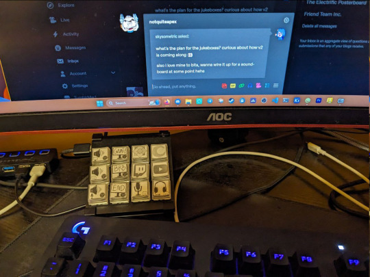
Ideally, the final version of the Jukebox would be sold with these (or similar) key caps, with a fun sticker sheet or something. The current "stickers" are made of printer paper, held in by the top and bottom halves of the keycap. I regularly use this while streaming and when I'm in Discord calls. It's great!
A big part of the reason the Jukebox still isn't finished, even with the whole independent study thing, is that I want it to be basically "finished" when I release it. Nothing new should need to be done with it once its out in the world. No firmware revisions, no bloated desktop applications. I want it to be something you can buy once and be happy with for the rest of your computing days, because lord knows we already have enough e-waste in the world. Designing products that last and that people want to use can be hard, especially when you're self funded and solo!

But I still have more plans for this thing, like this screen add-on for monitoring PC performance for weird PC building nerds like myself (or just anything, because it's a screen), and hopefully by next May it'll be ready for order proper. (Also ideally any old jukeboxes out there would just get a simple swap with the new ones. I'm already super in-the-red in terms of profit off these things, going in further wouldn't be so bad if it meant I got some of my old equipment and stuff back so I can use it for other things :D)
7 notes
·
View notes
Text
we did not in fact finish the lab due this morning or come even close BUT he’s giving us the next week with no late penalty bc it turns out one of the pins we were trying to use to communicate Actually Does Not Exist #slay
#personal#the engineering chronicles#it’s literally listed as an i2c pin in the tables but i overheard the student assistant say it’s not a real pin when i got into lab and was#like ?!?! and looked it up in the data sheet and for our version of this microcontroller yeah they replaced it with a capacitor for some#inexplicable reason and Left The Pin Label There. also need to stress that where it says it’s an i2c pin it IS listed under our specific#microcontroller like. technical writer of this data sheet when i catch you ‼️#so anyway. that was NOT the only issue we had even if the pin did exist it was supposed to be set for i2c2 and we accidentally set it for#i2c1 and also none of us has any clue what command to send to make the led on the other board like up but he doesn’t need to know that 🤫#*light up#even my prof didn’t know abt the secret nonexistent pin and he said no student of his has ever had this issue which actually i don’t think#is true bc i’ve been trying to avoid the b port all semester Specifically bc i remember having weird issues with the pins not working on it#last year and i suspect this is why but. yeah no consequences YIPPEE 🥳
3 notes
·
View notes
Text
The Universal Serial Bus is often not universal...
So there is this problem you often run into when doing development. You come up with a solution. You research the solution, and find only tiny amounts of people talking about it, and/or they seem to say many different things and disagree. Most of the time, that is for 2 reasons 1: it is a very novel solution, so no one have tried it much, and everyone who have, has made very custom versions of it. 2: There are variables that makes it impossible to do it in one single way. I needed a rechargeable battery system to power my robot. These can get... VERY complicated, and pre-made solutions can quickly be expensive and you might end up with batteries catching fire, or destroying the batteries so they can never be used again. You need protections on them, but which kind depends on a bunch of things. I know electronics, but I am mainly a software guy, and I know when I do not know enough about electronics to do it myself. This being such a case. So, I came up with the idea to use powerbanks. One for each steppermotor, and one for the microcontroller(so the noise fromt he motors could not cause issues).If I use ones that can output enough amperage, they should just work and they are cheap. They are meant to be used by normal costumers, so have all the protection needed, and are quite idiot-proof(Which is a very handy thing when you are an idiot, like me) so should be easy to use. But I could not find much info about doing this... and I did not realize I was looking at reason 2. Basically, BECAUSE powerbanks are idiotproof, they do not want to discharge themselves unless there is a real device at the end of the USB cable. So if they cannot detect one, they turn off after about a second. How do they determine if there is a real device? Depends on the power bank.... No really, there is NO standard way to do it, as far as I can tell. And it does not depend on the power bank MODEL. I have 2 identical power banks, bought at the same time, and they do NOT behave the same. Which means that when I connected the powerbanks to supply my system, they (SOMETIMES) did not supply anything. Some check how much current is being drawn, which can be faked with a resistor wasting some power. 500mA was being quoted a lot, but that is more of a "That is probably enough to get it going". Others check for impedance(Basically, also resistance, but from frequency dependent sources). Those can be "faked" by having a coil or a device that acts like one to the faking resistor. I wanted a tiny 5 volt fan to cool the stepper motor drivers anyway, so I had one power bank also power that. That ensured that it actually stayed on (But if I used the other, (identical!) power bank it just turned off anyway). The other one could be connected up directly. If I used the powerbanks lower amperage socket. If I used the high amperage one, it just turned off. So now it works... I have 2 powerbanks for the motors, each with painters tape marking which powerbank and socket to use for what. Took me a week longer than I had hoped to figure all this out and do all the experiments. Sometimes, things that should be simple are just headaches.
7 notes
·
View notes
Note
🪩
From the “I’ll make up the questions myself” ask game
🪩 Opinions on weird lighting?
The best weird lighting solutions are the ones you build yourself, with a soldering iron, and also a PCB and a microcontroller and perhaps some Neopixel addressable lights. I love me building some weird lights, but sometimes find I get bored with the results quickly. I need to build more.
Also, the term "addressable LED" for Neopixels bothers me. The things don't have addresses, just positions in a chain. They're individually controllable even in long strings, which is great, but there is no address, you just say "colors for the first LED, colors for the one after that, colors for the one after that…" and so on. I guess the term Neopixel, being a marketing term coined and probably trademark by exactly one dealer, is not great either, but I like it more.
2 notes
·
View notes
Text
tbh one of the things I really like about the PC platform is that it's still - despite all the attempts to make it less so - a relatively open and flexible platform in a way that few others really are, especially these days. You can mix and match hardware from all over the place, sometimes even surprisingly old hardware with the right conversion bits, and several interfacing standards are open and documented to the point where you could literally make your own USB devices or ISA/PCI/PCIe expansion cards given the proper hardware and know-how.
And sure, most of us are never going to have either the tools or technical expertise necessary to make our own PC components or peripherals, but the platform is still open enough to have the kind of wide cross-compatibility where at least in theory any peripheral or piece of hardware could in theory be adapted to work with it - it's simply a matter of someone figuring out a way to make it work and giving others the means to replicate what they did.
I could take literally any kind of input peripheral, be it a joystick, keyboard, gamepad, mouse, or whatever, and chances are someone out there will already have made some kind of adapter to let me hook it up to my PC if I wanted - and in the rare case that none exists to buy, there's still likely to be enough information around that I could use a cheap USB microcontroller as a go-between to make it work.
also look you basically have no idea how excited I am to have discovered that the mainboard I'm looking to get for a much needed PC rebuild somehow has an old 9-pin header for a serial COM port
4 notes
·
View notes
Note
physicist and embedded systems engineer??? what did you do for college I need your life
I just did physics, like the whole route, Bachelor's, Master's, PhD, although heavily specializing in numerics, so 90% of my phd was programming.
Realized academia is a trap (and also fundamentally incompatible with the life I want), so I applied for software engineering positions instead of postdocs. Got hired into an embedded software team and learned how to program microcontrollers. Turns out it's surprisingly similar to programming supercomputers :)
3 notes
·
View notes
Text

High Performance and Efficiency PIC MCU Introducing the PIC16F1937-I/PT microcontroller,a state-of-the-art solution designed to power your embedded systems with exceptional performance and flexibility. Whether you're a hobbyist or a professional engineer, this microcontroller is tailored to meet your needs with an innovative architecture and a comprehensive array of features. The PIC16F1937-I/PT features an extensive 14-bit instruction set architecture that allows for high-level programming efficiency. Operating at speeds up to 32 MHz, it delivers quick processing, ensuring that your applications run smoothly without bottlenecking. This microcontroller also offers a range of memory options, with up to 4 KB of Flash memory and 256 bytes of SRAM, giving you ample space for complex programs and data handling. MOQ of PIC16F1937-I/PT As seen online, price default quantity in the blanket is 100units.So it starts to order for 100pcs with shipping.If you interested with much more quantity,maybe we can count it free shipping or little discount.Inquire us to chat and talk details. Equipped with a rich set of peripherals, the PIC16F1937-I/PT is ideal for a variety of applications, from motor control and data acquisition to wireless communication. With integrated analog-to-digital converters (ADCs), digital-to-analog converters (DACs), and various communication interfaces like UART, SPI, and I2C, this microcontroller offers unmatched versatility. Additionally, the built-in PWM capabilities make it perfect for driving motors or LED projects, providing precise control and operation. Robust and Reliable for Diverse Applications of the Microcontroller Designed with reliability in mind, the PIC16F1937-I/PT ensures stability in the most demanding environments. The microcontroller's enhanced features, such as watchdog timers and enhanced interrupt handling, guarantee robust operation and help reduce system failures. By adopting Microchip's proven technology, engineers can cultivate trust in their products, which is essential in fields such as automotive, industrial automation, and consumer electronics. In summary, the PIC16F1937-I/PT microcontroller combines high performance, advanced peripheral integration, and reliability into a compact package suitable for a plethora of applications. Elevate your projects today with this versatile microcontroller — the ideal partner for your development and innovation needs. Note:We not only provide this parts number,but also available for other,check the electronic components price here.Know more about our company business.0 Read the full article
0 notes
Text
Matrix Connection: Few Pins, Many Options

4+4=8, 4×4=16. It often happens that a microcontroller or other chip has too few pins. You can use a more complex and expensive microcontroller, or you can multiplex the pins. Today I will describe one of the ways to do this.
In previous posts, we have already talked about decoders and demultiplexers, as well as shift registers.
In the first case, an n-bit binary number can point to one of the decoder outputs, the number of which is equal to two to the power of n.
For example, the 74HC138 3:8 demultiplexer chip allows you to light up eight LEDs or turn on eight relays using only three microcontroller pins or three communication wires between devices.

However, this scheme does not allow activating several outputs simultaneously. In the case of LEDs, we can take advantage of the persistence of human vision and constantly send different numbers to the inputs of the 74HC138. If the frequency of numbers changing exceeds 24 hertz, then it will seem to us that from 0 to 8 LEDs are lit simultaneously and continuously.
It should be noted that the more LEDs are used, the dimmer each of them will be. Although in some cases this is a good thing, the consistency of the overall brightness means that when more LEDs are turned on, they will not be blinding.
It is also possible to turn on several relays simultaneously through a decoder, although it is more difficult. Timing circuits similar to those used in running lights with slowly dimming LEDs will be required.

Thanks to diodes with RC circuits at the bases of transistors, relay coils connected instead of LEDs will switch off not at the same moment as the signal disappears from the decoder output but after a certain period of time.
If you keep the capacitor charged by periodically applying the corresponding number to the decoder input, the relay remains on. If you stop transmitting this number, the relay will turn off.
This is very similar to the operation of the Williams-Kilburn tube, one of the first types of computer memory in history. The electron beam scanned the cathode-ray tube screen, just like a television.

To turn the indicator into a storage device, engineers simply added a matrix of electrodes onto the screen and synchronized the modulation of the beam with the scanning of this matrix. Those areas of the glass where the electrons hit acquired a charge that would fade if not renewed.
Of course, this was not a fast memory by any stretch. And controlling a relay via an RC chain is also not fast. However, it fits a number of applications.
Each additional wire or microcontroller pin doubles the capacity of the demultiplexer. For example, 4 bits give 16 outputs. But the required number of decoder chips also doubles. For 4:16 you need two 3:8 chips, for 5:32 you need four, and for 6:64 as many as eight, and so on.

But the shift register allows you to transmit or read practically an unlimited number of binary bits using only three wires: one for data, one for clocking, and one for register latching.

Therefore, when paired with microcontrollers, to expand the number of pins, shift registers are most often used rather than demultiplexers.
Two CD4017 decimal counter-decoders have 2×10=20 outputs. But if you make a matrix where one chip scans the rows and the second the columns, you get 10×10=100. Or 9×9=81, as done in this matrix LED effect.

The same design is used in an electronic timer, where 6×10=60 LEDs are placed around the circumference of the dial and serve as the second hand.

As you can see, the matrix is not necessarily square or rectangular. It can be stretched into a line or closed into a circle, and in general, its elements can be arranged in the shape you need.

The decade counter U2 receives timing signals with a frequency of 1 hertz from the generator on the 555 timer. Using switch SW1, you can switch the chip to 'disable counting' mode, which means a pause in the stopwatch operation.
U2 counts to ten (from Q0 to Q9) and transmits the CARRY-OUT signal to the clock input of U1. Note that CARRY-OUT goes to logical zero when the counter has counted to Q5, and to logical one at the moment of overflow, when Q0 is activated again after Q9.

The CD4017 chip reacts just to the transition from low to high, so U1 will turn on the next row of LEDs exactly when U2 has turned off column Q9 and turned on Q0.
The active voltage level at the outputs Q0..Q9 of the CD4017 counter is high, and the current in the LED should flow from plus to minus, from anode to cathode, in the direction of the arrow. Therefore, the signals from the U2 outputs are inverted by the U3 CD4069 chip.
This chip contains six logic inverters. To count 60=10×6 seconds, we just need 6 lines of 10 LEDs. On the diagram, they look like rows and columns, but on the board, they are placed around the circumference of the dial.
After a minute has passed and Q2 has counted to Q6, transistor Q1 opens through resistor R2, performing two actions in our circuit.
First, it charges the capacitor C1, the voltage across which turns on transistor Q2 through resistor R3. This is exactly the same scheme that we've discussed above.
While C1 is discharging, the BZ1 buzzer will beep, not continuously but in 1 hertz pulses, since the positive terminal of BZ1 is connected not to the positive power supply terminal but to the output of the second pulse generator.
An asymmetrical flip-flop is constructed on transistors Q3 and Q4. A logical one from capacitor C1 through diode D1 and resistor R4, or from the power supply positive through R5 and button SW3, sets the flip-flop to one, which goes to the reset input of both counters, stopping the counting and resetting them to zero.
The diode is needed so that the buzzer is triggered only at the end of the count, not when the STOP button is pressed or a logical one appears at the output of the trigger through resistor R6, which latches the trigger into a high- or low-level state.
Button SW2 resets the trigger and starts the second count. If you made a multi-position switch that allowed you to choose which of the Q1..Q6 pins to connect R2 to, the timer could count not only up to 60 but also up to 10, 20, 30, 40, and 50 seconds.
And the last circuit for today is an RGB running light. Here IC1 is the familiar CD4060 binary counter, and 74HC138 is a 3:8 decoder that lights up one of the eight LEDs, LED1..LED8.

These are RGB LEDs, and the light color will depend on the state of the outputs Q8–Q10 of the IC1 chip.
000: white; all channels are on
001: blue-green
010: magenta; blue plus red
011: blue
100: yellow; red plus green
101: green
110: red
111: LEDs do not light up
As you can see, even to control RGB LEDs, it is not at all necessary to use a microcontroller. With two simple chips and three transistors, you can create the beautiful effect of a running, color-changing light.
0 notes