#photodetectors
Text

Researchers create dispersion-assisted photodetector to decipher high-dimensional light
A new study published in Nature, conducted by an international collaboration team led by Prof. Wei Li from the Changchun Institute of Optics, Fine Mechanics and Physics (CIOMP) of the Chinese Academy of Sciences, introduces a novel miniaturized photodetector capable of characterizing arbitrary polarization states across a broadband spectrum with a single device and a single measurement.
"Traditional photodetectors are limited to measuring light intensity alone. Existing polarization and spectrum photodetectors often rely on the complex integration of multiple polarization- or wavelength-sensitive elements in time or space to enhance detection capabilities," said Professor Wei Li.
"Current photodetectors typically sacrifice one dimension of information for another; they can measure either intensity and polarization at a fixed wavelength or intensity and wavelength under uniform polarization.
Read more.
15 notes
·
View notes
Text
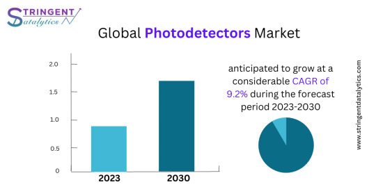
Quantum Dot Photodetectors Market Analysis, Size, Share, Growth, Trends, and Forecasts 2023-2030
In the advanced optoelectronic technologies, the Quantum Dot Photodetectors market stands as a beacon of innovation and promise. These photodetectors, harnessed from the fascinating principles of quantum dots, represent a groundbreaking leap in light sensing applications. As we delve into the essence of Quantum Dot Photodetectors, it becomes evident that their significance lies not only in their remarkable sensitivity to light but also in their ability to transcend the limitations of traditional photodetectors.
Get a Free Sample Report:https://www.metastatinsight.com/request-sample/2515

#QuantumDot#Photodetectors#market#marketsize#marketoutlook#marketkeytrends#marketshares#marketforecast#industryanalysis#businessinsights#intelligence#marketgrowth#marketanalysis#marketdemand#marketreport#markettrend#marketresearch
0 notes
Text
Conceptual Design for a Neutrino Power Transmission System
Overview
Neutrinos could potentially be used to send electricity over long distances without the need for high-voltage direct current (HVDC) lines. Neutrinos have the unique property of being able to pass through matter without interacting with it, which makes them ideal for transmitting energy over long distances without significant energy loss. This property allows neutrinos to be used as a medium for energy transmission, potentially replacing HVDC lines in certain applications.
So the goal is to create a neutrino-based power transmission system capable of sending and receiving a beam of neutrinos that carry a few MW of power across a short distance. This setup will include a neutrino beam generator (transmitter), a travel medium, and a neutrino detector (receiver) that can convert the neutrinos' kinetic energy into electrical power.
1. Neutrino Beam Generator (Transmitter)
Particle Accelerator: At the heart of the neutrino beam generator will be a particle accelerator. This accelerator will increase the energy of protons before colliding them with a target to produce pions and kaons, which then decay into neutrinos. A compact linear accelerator or a small synchrotron could be used for this purpose.
Target Material: The protons accelerated by the particle accelerator will strike a dense material target (like tungsten or graphite) to create a shower of pions and kaons.
Decay Tunnel: After production, these particles will travel through a decay tunnel where they decay into neutrinos. This tunnel needs to be under vacuum or filled with inert gas to minimize interactions before decay.
Focusing Horns: Magnetic horns will be used to focus the charged pions and kaons before they decay, enhancing the neutrino beam's intensity and directionality.
Energy and Beam Intensity: To achieve a few MW of power, the system will need to operate at several gigaelectronvolts (GeV) with a proton beam current of a few tens of milliamperes.
2. Travel Medium
Direct Line of Sight: Neutrinos can travel through the Earth with negligible absorption or scattering, but for initial tests, a direct line of sight through air or vacuum could be used to simplify detection.
Distance: The initial setup could span a distance from a few hundred meters to a few kilometers, allowing for measurable neutrino interactions without requiring excessively large infrastructure.
3. Neutrino Detector (Receiver)
Detector Medium: A large volume of water or liquid scintillator will be used as the detecting medium. Neutrinos interacting with the medium produce a charged particle that can then be detected via Cherenkov radiation or scintillation light.
Photodetectors: Photomultiplier tubes (PMTs) or Silicon Photomultipliers (SiPMs) will be arranged around the detector medium to capture the light signals generated by neutrino interactions.
Energy Conversion: The kinetic energy of particles produced in neutrino interactions will be converted into heat. This heat can then be used in a traditional heat-to-electricity conversion system (like a steam turbine or thermoelectric generators).
Shielding and Background Reduction: To improve the signal-to-noise ratio, the detector will be shielded with lead or water to reduce background radiation. A veto system may also be employed to distinguish neutrino events from other particle interactions.
4. Control and Data Acquisition
Synchronization: Precise timing and synchronization between the accelerator and the detector will be crucial to identify and correlate neutrino events.
Data Acquisition System: A high-speed data acquisition system will collect data from the photodetectors, processing and recording the timing and energy of detected events.
Hypothetical Power Calculation
To estimate the power that could be transmitted:
Neutrino Flux: Let the number of neutrinos per second be ( N_\nu ), and each neutrino carries an average energy ( E_\nu ).
Neutrino Interaction Rate: Only a tiny fraction (( \sigma )) of neutrinos will interact with the detector material. For a detector with ( N_d ) target nuclei, the interaction rate ( R ) is ( R = N_\nu \sigma N_d ).
Power Conversion: If each interaction deposits energy ( E_d ) into the detector, the power ( P ) is ( P = R \times E_d ).
For a beam of ( 10^{15} ) neutrinos per second (a feasible rate for a small accelerator) each with ( E_\nu = 1 ) GeV, and assuming an interaction cross-section ( \sigma \approx 10^{-38} ) cm(^2), a detector with ( N_d = 10^{30} ) (corresponding to about 10 kilotons of water), and ( E_d = E_\nu ) (for simplicity in this hypothetical scenario), the power is:
[ P = 10
^{15} \times 10^{-38} \times 10^{30} \times 1 \text{ GeV} ]
[ P = 10^{7} \times 1 \text{ GeV} ]
Converting GeV to joules (1 GeV ≈ (1.6 \times 10^{-10}) J):
[ P = 10^{7} \times 1.6 \times 10^{-10} \text{ J/s} ]
[ P = 1.6 \text{ MW} ]
Thus, under these very optimistic and idealized conditions, the setup could theoretically transmit about 1.6 MW of power. However, this is an idealized maximum, and actual performance would likely be significantly lower due to various inefficiencies and losses.
Detailed Steps to Implement the Conceptual Design
Step 1: Building the Neutrino Beam Generator
Accelerator Design:
Choose a compact linear accelerator or a small synchrotron capable of accelerating protons to the required energy (several GeV).
Design the beamline with the necessary magnetic optics to focus and direct the proton beam.
Target Station:
Construct a target station with a high-density tungsten or graphite target to maximize pion and kaon production.
Implement a cooling system to manage the heat generated by the high-intensity proton beam.
Decay Tunnel:
Design and construct a decay tunnel, optimizing its length to maximize the decay of pions and kaons into neutrinos.
Include magnetic focusing horns to shape and direct the emerging neutrino beam.
Safety and Controls:
Develop a control system to synchronize the operation of the accelerator and monitor the beam's properties.
Implement safety systems to manage radiation and operational risks.
Step 2: Setting Up the Neutrino Detector
Detector Medium:
Select a large volume of water or liquid scintillator. For a few MW of transmitted power, consider a detector size of around 10 kilotons, similar to large neutrino detectors in current experiments.
Place the detector underground or in a well-shielded facility to reduce cosmic ray backgrounds.
Photodetectors:
Install thousands of photomultiplier tubes (PMTs) or Silicon Photomultipliers (SiPMs) around the detector to capture light from neutrino interactions.
Optimize the arrangement of these sensors to maximize coverage and detection efficiency.
Energy Conversion System:
Design a system to convert the kinetic energy from particle reactions into heat.
Couple this heat to a heat exchanger and use it to drive a turbine or other electricity-generating device.
Data Acquisition and Processing:
Implement a high-speed data acquisition system to record signals from the photodetectors.
Develop software to analyze the timing and energy of events, distinguishing neutrino interactions from background noise.
Step 3: Integration and Testing
Integration:
Carefully align the neutrino beam generator with the detector over the chosen distance.
Test the proton beam operation, target interaction, and neutrino production phases individually before full operation.
Calibration:
Use calibration sources and possibly a low-intensity neutrino source to calibrate the detector.
Adjust the photodetector and data acquisition settings to optimize signal detection and reduce noise.
Full System Test:
Begin with low-intensity beams to ensure the system's stability and operational safety.
Gradually increase the beam intensity, monitoring the detector's response and the power output.
Operational Refinement:
Refine the beam focusing and detector sensitivity based on initial tests.
Implement iterative improvements to increase the system's efficiency and power output.
Challenges and Feasibility
While the theoretical framework suggests that a few MW of power could be transmitted via neutrinos, several significant challenges would need to be addressed to make such a system feasible:
Interaction Rates: The extremely low interaction rate of neutrinos means that even with a high-intensity beam and a large detector, only a tiny fraction of the neutrinos will be detected and contribute to power generation.
Technological Limits: The current state of particle accelerator and neutrino detection technology would make it difficult to achieve the necessary beam intensity and detection efficiency required for MW-level power transmission.
Cost and Infrastructure: The cost of building and operating such a system would be enormous, likely many orders of magnitude greater than existing power transmission systems.
Efficiency: Converting the kinetic energy of particles produced in neutrino interactions to electrical energy with high efficiency is a significant technical challenge.
Scalability: Scaling this setup to practical applications would require even more significant advancements in technology and reductions
in cost.
Detailed Analysis of Efficiency and Cost
Even in an ideal scenario where technological barriers are overcome, the efficiency of converting neutrino interactions into usable power is a critical factor. Here’s a deeper look into the efficiency and cost aspects:
Efficiency Analysis
Neutrino Detection Efficiency: Current neutrino detectors have very low efficiency due to the small cross-section of neutrino interactions. To improve this, advanced materials or innovative detection techniques would be required. For instance, using superfluid helium or advanced photodetectors could potentially increase interaction rates and energy conversion efficiency.
Energy Conversion Efficiency: The process of converting the kinetic energy from particle reactions into usable electrical energy currently has many stages of loss. Thermal systems, like steam turbines, typically have efficiencies of 30-40%. To enhance this, direct energy conversion methods, such as thermoelectric generators or direct kinetic-to-electric conversion, need development but are still far from achieving high efficiency at the scale required.
Overall System Efficiency: Combining the neutrino interaction efficiency and the energy conversion efficiency, the overall system efficiency could be extremely low. For neutrino power transmission to be comparable to current technologies, these efficiencies need to be boosted by several orders of magnitude.
Cost Considerations
Capital Costs: The initial costs include building the particle accelerator, target station, decay tunnel, focusing system, and the neutrino detector. Each of these components is expensive, with costs potentially running into billions of dollars for a setup that could aim to transmit a few MW of power.
Operational Costs: The operational costs include the energy to run the accelerator and the maintenance of the entire system. Given the high-energy particles involved and the precision technology required, these costs would be significantly higher than those for traditional power transmission methods.
Cost-Effectiveness: To determine the cost-effectiveness, compare the total cost per unit of power transmitted with that of HVDC systems. Currently, HVDC transmission costs are about $1-2 million per mile for the infrastructure, plus additional costs for power losses over distance. In contrast, a neutrino-based system would have negligible losses over distance, but the infrastructure costs would dwarf any current system.
Potential Improvements and Research Directions
To move from a theoretical concept to a more practical proposition, several areas of research and development could be pursued:
Advanced Materials: Research into new materials with higher sensitivity to neutrino interactions could improve detection rates. Nanomaterials or quantum dots might offer new pathways to detect and harness the energy from neutrino interactions more efficiently.
Accelerator Technology: Developing more compact and efficient accelerators would reduce the initial and operational costs of generating high-intensity neutrino beams. Using new acceleration techniques, such as plasma wakefield acceleration, could significantly decrease the size and cost of accelerators.
Detector Technology: Improvements in photodetector efficiency and the development of new scintillating materials could enhance the signal-to-noise ratio in neutrino detectors. High-temperature superconductors could also be used to improve the efficiency of magnetic horns and focusing devices.
Energy Conversion Methods: Exploring direct conversion methods, where the kinetic energy of particles from neutrino interactions is directly converted into electricity, could bypass the inefficiencies of thermal conversion systems. Research into piezoelectric materials or other direct conversion technologies could be key.
Conceptual Experiment to Demonstrate Viability
To demonstrate the viability of neutrino power transmission, even at a very small scale, a conceptual experiment could be set up as follows:
Experimental Setup
Small-Scale Accelerator: Use a small-scale proton accelerator to generate a neutrino beam. For experimental purposes, this could be a linear accelerator used in many research labs, capable of accelerating protons to a few hundred MeV.
Miniature Target and Decay Tunnel: Design a compact target and a short decay tunnel to produce and focus neutrinos. This setup will test the beam production and initial focusing systems.
Small Detector: Construct a small-scale neutrino detector, possibly using a few tons of liquid scintillator or water, equipped with sensitive photodetectors. This detector will test the feasibility of detecting focused neutrino beams at short distances.
Measurement and Analysis: Measure the rate of neutrino interactions and the energy deposited in the detector. Compare this to the expected values based on the beam properties and detector design.
Steps to Conduct the Experiment
Calibrate the Accelerator and Beamline: Ensure the proton beam is correctly tuned and the target is accurately positioned to maximize pion and kaon production.
Operate the Decay Tunnel and Focusing System: Run tests to optimize the magnetic focusing horns and maximize the neutrino beam coherence.
Run the Detector: Collect data from the neutrino interactions, focusing on capturing the rare events and distinguishing them from background noise.
Data Analysis: Analyze the collected data to determine the neutrino flux and interaction rate, and compare these to
theoretical predictions to validate the setup.
Optimization: Based on initial results, adjust the beam energy, focusing systems, and detector configurations to improve interaction rates and signal clarity.
Example Calculation for a Proof-of-Concept Experiment
To put the above experimental setup into a more quantitative framework, here's a simplified example calculation:
Assumptions and Parameters
Proton Beam Energy: 500 MeV (which is within the capability of many smaller particle accelerators).
Number of Protons per Second ((N_p)): (1 \times 10^{13}) protons/second (a relatively low intensity to ensure safe operations for a proof-of-concept).
Target Efficiency: Assume 20% of the protons produce pions or kaons that decay into neutrinos.
Neutrino Energy ((E_\nu)): Approximately 30% of the pion or kaon energy, so around 150 MeV per neutrino.
Distance to Detector ((D)): 100 meters (to stay within a compact experimental facility).
Detector Mass: 10 tons of water (equivalent to (10^4) kg, or about (6 \times 10^{31}) protons assuming 2 protons per water molecule).
Neutrino Interaction Cross-Section ((\sigma)): Approximately (10^{-38} , \text{m}^2) (typical for neutrinos at this energy).
Neutrino Detection Efficiency: Assume 50% due to detector design and quantum efficiency of photodetectors.
Neutrino Production
Pions/Kaons Produced:
[ N_{\text{pions/kaons}} = N_p \times 0.2 = 2 \times 10^{12} \text{ per second} ]
Neutrinos Produced:
[ N_\nu = N_{\text{pions/kaons}} = 2 \times 10^{12} \text{ neutrinos per second} ]
Neutrino Flux at the Detector
Given the neutrinos spread out over a sphere:
[ \text{Flux} = \frac{N_\nu}{4 \pi D^2} = \frac{2 \times 10^{12}}{4 \pi (100)^2} , \text{neutrinos/m}^2/\text{s} ]
[ \text{Flux} \approx 1.6 \times 10^7 , \text{neutrinos/m}^2/\text{s} ]
Expected Interaction Rate in the Detector
Number of Target Nuclei ((N_t)) in the detector:
[ N_t = 6 \times 10^{31} ]
Interactions per Second:
[ R = \text{Flux} \times N_t \times \sigma \times \text{Efficiency} ]
[ R = 1.6 \times 10^7 \times 6 \times 10^{31} \times 10^{-38} \times 0.5 ]
[ R \approx 48 , \text{interactions/second} ]
Energy Deposited
Energy per Interaction: Assuming each neutrino interaction deposits roughly its full energy (150 MeV, or (150 \times 1.6 \times 10^{-13}) J):
[ E_d = 150 \times 1.6 \times 10^{-13} , \text{J} = 2.4 \times 10^{-11} , \text{J} ]
Total Power:
[ P = R \times E_d ]
[ P = 48 \times 2.4 \times 10^{-11} , \text{J/s} ]
[ P \approx 1.15 \times 10^{-9} , \text{W} ]
So, the power deposited in the detector from neutrino interactions would be about (1.15 \times 10^{-9}) watts.
Challenges and Improvements for Scaling Up
While the proof-of-concept might demonstrate the fundamental principles, scaling this up to transmit even a single watt of power, let alone megawatts, highlights the significant challenges:
Increased Beam Intensity: To increase the power output, the intensity of the proton beam and the efficiency of pion/kaon production must be dramatically increased. For high power levels, this would require a much higher energy and intensity accelerator, larger and more efficient targets, and more sophisticated focusing systems.
Larger Detector: The detector would need to be massively scaled
up in size. To detect enough neutrinos to convert to a practical amount of power, we're talking about scaling from a 10-ton detector to potentially tens of thousands of tons or more, similar to the scale of detectors used in major neutrino experiments like Super-Kamiokande in Japan.
Improved Detection and Conversion Efficiency: To realistically convert the interactions into usable power, the efficiency of both the detection and the subsequent energy conversion process needs to be near-perfect, which is far beyond current capabilities.
Steps to Scale Up the Experiment
To transition from the initial proof-of-concept to a more substantial demonstration and eventually to a practical application, several steps and advancements are necessary:
Enhanced Accelerator Performance:
Upgrade to Higher Energies: Move from a 500 MeV system to several GeV or even higher, as higher energy neutrinos can penetrate further and have a higher probability of interaction.
Increase Beam Current: Amplify the proton beam current to increase the number of neutrinos generated, aiming for a beam power in the range of hundreds of megawatts to gigawatts.
Optimized Target and Decay Tunnel:
Target Material and Design: Use advanced materials that can withstand the intense bombardment of protons and optimize the geometry for maximum pion and kaon production.
Magnetic Focusing: Refine the magnetic horns and other focusing devices to maximize the collimation and directionality of the produced neutrinos, minimizing spread and loss.
Massive Scale Detector:
Detector Volume: Scale the detector up to the kiloton or even megaton range, using water, liquid scintillator, or other materials that provide a large number of target nuclei.
Advanced Photodetectors: Deploy tens of thousands of high-efficiency photodetectors to capture as much of the light from interactions as possible.
High-Efficiency Energy Conversion:
Direct Conversion Technologies: Research and develop technologies that can convert the kinetic energy from particle reactions directly into electrical energy with minimal loss.
Thermodynamic Cycles: If using heat conversion, optimize the thermodynamic cycle (such as using supercritical CO2 turbines) to maximize the efficiency of converting heat into electricity.
Integration and Synchronization:
Data Acquisition and Processing: Handle the vast amounts of data from the detector with real-time processing to identify and quantify neutrino events.
Synchronization: Ensure precise timing between the neutrino production at the accelerator and the detection events to accurately attribute interactions to the beam.
Realistic Projections and Innovations Required
Considering the stark difference between the power levels in the initial experiment and the target power levels, let's outline the innovations and breakthroughs needed:
Neutrino Production and Beam Focus: To transmit appreciable power via neutrinos, the beam must be incredibly intense and well-focused. Innovations might include using plasma wakefield acceleration for more compact accelerators or novel superconducting materials for more efficient and powerful magnetic focusing.
Cross-Section Enhancement: While we can't change the fundamental cross-section of neutrino interactions, we can increase the effective cross-section by using quantum resonance effects or other advanced physics concepts currently in theoretical stages.
Breakthrough in Detection: Moving beyond conventional photodetection, using quantum coherent technologies or metamaterials could enhance the interaction rate detectable by the system.
Scalable and Safe Operation: As the system scales, ensuring safety and managing the high-energy particles and radiation produced will require advanced shielding and remote handling technologies.
Example of a Scaled Concept
To visualize what a scaled-up neutrino power transmission system might look like, consider the following:
Accelerator: A 10 GeV proton accelerator, with a beam power of 1 GW, producing a focused neutrino beam through a 1 km decay tunnel.
Neutrino Beam: A beam with a diameter of around 10 meters at production, focused down to a few meters at the detector site several kilometers away.
Detector: A 100 kiloton water Cherenkov or liquid scintillator detector, buried deep underground to minimize cosmic ray backgrounds, equipped with around 100,000 high-efficiency photodetectors.
Power Output: Assuming we could improve the overall system efficiency to even 0.1% (a huge leap from current capabilities), the output power could be: [ P_{\text{output}} = 1\text{ GW} \times 0.001 = 1\text{ MW} ]
This setup, while still futuristic, illustrates the scale and type of development needed to make neutrino power transmission a feasible alternative to current technologies.
Conclusion
While the concept of using neutrinos to transmit power is fascinating and could overcome many limitations of current power transmission infrastructure, the path from theory to practical application is long and filled with significant hurdels.
#Neutrino Energy Transmission#Particle Physics#Neutrino Beam#Neutrino Detector#High-Energy Physics#Particle Accelerators#Neutrino Interaction#Energy Conversion#Direct Energy Conversion#High-Voltage Direct Current (HVDC)#Experimental Physics#Quantum Materials#Nanotechnology#Photodetectors#Thermoelectric Generators#Superfluid Helium#Quantum Dots#Plasma Wakefield Acceleration#Magnetic Focusing Horns#Cherenkov Radiation#Scintillation Light#Silicon Photomultipliers (SiPMs)#Photomultiplier Tubes (PMTs)#Particle Beam Technology#Advanced Material Science#Cost-Effectiveness in Energy Transmission#Environmental Impact of Energy Transmission#Scalability of Energy Systems#Neutrino Physics#Super-Kamiokande
0 notes
Text
Perovskite, a versatile mineral structure, is transforming renewable energy. Researchers are enhancing solar cells, achieving remarkable efficiency gains. Beyond solar energy, perovskite offers potential in LEDs, photocatalysts, and photodetectors.
1 note
·
View note
Text
Photodetectors Market
0 notes
Text
Optical switch, Electrical connector, Optical sensor, what is an optical sensor
ILD207T Series Dual Channel 70 V 4000 Vrms Phototransistor Optocoupler - SOIC-8
#Optoelectronics#Isolation Components#Optocouplers#ILD207T#Vishay#Optical switch#Electrical connector#Optical sensor#what is an optical sensor#Integrated circuit#Photodetectors#optical switch#Digital optical switch#optical sensors#Electrical board to board connectors#what is an optical switch
1 note
·
View note
Text

Trying out my old point and shoot camera again
#y2k#y2k aesthetic#journal#travelers notebook#journaling#I’ve heard these are supposed to give a film-like quality because of the sensors#we’ll see#it might be too new to really give that effect but it does have CCD photodetectors
24 notes
·
View notes
Text
#Avalanche Photodiode Market#Avalanche Photodiode#Silicon Photodiode#Germanium Photodiode#APD Photodiode#Avalanche Photodetector#Ingaas APD
0 notes
Text
What Are MSM Photodetector?

A metal-semiconductor-metal photodetector (MSM phodetector) is a photodetector device containing two Schottky contacts (i.e., two metallic electrodes on a semiconductor material) rather than a p-n junction as in a photodiode.
Get more details: What Are MSM Photodetector?
#electronics#integrated circuits#semiconductor#components#electronic#module#electronic devices#chips#manufacturing#package#photodetector
0 notes
Text
Webinar on High Performance RF Filters in a Photonic Chip.

Photonic integration brings the promise of significant cost, power and space savings and propels the real applications of microwave photonic technology. In this paper, a multiband radio frequency (RF) signal simultaneous receiver using an optical bandpass filter (OBPF) integrated with a photodetector (PD) on a chip is proposed, which was experimentally demonstrated. The OBPF was composed of ring-assisted Mach–Zehnder interferometer with a periodical bandpass response featuring a box-like spectral shape. The OBPF was connected to a PD and then integrated on to a single silicon photonic chip. Phase-modulated multiband RF signals transmitted from different locations were inputted into the OBPF, by which one RF sideband was filtered out and the phase modulation to intensity modulation conversion was realized. The single sideband with carrier
signals were then simultaneously detected by the PD. A proof-of-concept experiment with the silicon photonic integrated chip was implemented to simultaneously receive four channels of 8 GHz, 12 GHz, 14 GHz and 18 GHz in the X- and Ku-bands. The performance of the integrated microwave photonic multiband receiver—including the receiving sensitivity, the spurious free dynamic range, the gain
and the noise figure across the whole operation frequency band—was characterized in detail.
#photodetector (PD)#optical bandpass filter (OBPF)#radio frequency (RF) signal#photonic integration#microwave photonics#silicon photonic chip#Indonesia
0 notes
Text
What Distinguishes a Phototransistor from a Photodiode?
A phototransistor is a photosensitive transistor that is used to boost the photocurrent produced by changing the energy of light.
A photodiode is an electrically powered photosensitive diode that transforms light energy. It is constructed out of silicon or germanium. It is a single-PN junction device that employs the photoelectric effect as its governing theory.
Comparing photodiode and phototransistor: Key Differences
1. A semiconductor called a photodiode transforms light energy into an electrical current.
The phototransistor, however, employs a transistor to transform light energy into an electrical current.
2. Because the phototransistor generates a significant output current, the photodiode is less sensitive than the phototransistor.
3. The phototransistor only operates in forward biasing, but the photodiode can operate in both forward and reversed biasing.
4. The phototransistor is used to detect light, whereas the photodiode is utilized in solar power plants, light meters, etc.
NEON is a supplier of highly designed commercial and military off-the-shelf or custom modules created for today's state-of-the-art defense systems and high-speed optical communication network infrastructures. NEON invented RF photonics, microwave photonics, and optical delay line technology in order to successfully implement features like ultra-wideband, high dynamic range, RF system integration, etc. From NEON, you can choose and purchase a high-speed photodetector.
0 notes
Text

Fundamental and photodetector application of van der Waals Schottky junctions
The junction composed of traditional metals and 2D semiconductors is a key component of semiconductor devices.
Ideally, Schottky barrier height (SBH) can be obtained based on the relative alignment of energy levels according to the Schottky-Mott rule. However, the Schottky-Mott rule was invalid due to the Fermi level pinning (FLP) effect, it is difficult to tune SBH by changing the work function of metals. The precise design and modulation of SBH is challenging and the issue of FLP should be addressed.
In this review, the authors summarized the fundamental concept of vdW Schottky junction, including the band alignment at the interface and the SBH extraction models. Then the origins of FLP and the strategies to eliminate FLP were introduced.
In terms of 2D surface contact, inserting buffer layer, vdW contact with 3D metal by dry transfer method and constructing all 2D vdW contact using semimetallic 2D materials were introduced respectively to minimize SBH.
Read more.
8 notes
·
View notes
Text

Image Credits: ESA and the SPIRE & PACS consortia, Ph. André (CEA Saclay) for the Gould’s Belt Key Programme Consortia
W40 (also known as Sh2-64 and RCW 174) is a stellar nursery or some 25 light-years across, between 1,000 and 2,000 light years-away from Earth in the conquila (the Eagle) close to the border with Serpenss Cauda (Serpent’s Tail).
This dark cloud is one of the nearest massive star-forming (HII) regions, known and is part of Gould’s Belt, a giant ring of stars – tilted to the Milky Way by 20 degrees that circles the night sky because the Solar System just happens to lie near the center of the call.
The stellar nursery is so shrouded in dust that no infrared satellite before Herschel has been to able to see into it. Thanks to Herschel’s superior sensitivity at the longest wavelengths of infrared, I’m showing you the first picture of the interior of W40.
Altogether, about 600 newly forming stars are crowded into colorful these filaments of dust. It is estimated that about 150 of these are protostars, celestial objects in the final stages of formation. Each one just needs to ignite nuclear fusion in its core to become a true star. The other 450 objects are insufficiently developed to considered protostars, but theses too will will become stars.
The blue area is home to a young OB association with at least three young massive OB stars that are illuminating the ionized hydrogen gas, causing it to shine. (OBB associations usually contain 10–100 massive stars of spectral class O and B and, in addition, hundreds, or of low- and intermediate-mass stars).
The bright nebula is expanding into the medium, compressing the ambient gas on its way. This has created a second generation of young very protostars which are only seen at the far-infrared wavelengths accessible to Herschel.
At least 50 percent of the stars in our Milky Way galaxy formed in massive clusters of thousands of stars similar to W40. Evidence suggests that the Solar System developed in such a cluster almost 5 billion years ago.
W40 is difficult to view with optical telescopes because it lies less than 3 degrees from the main plane of the Milky Way, behind obscuring clouds of interstellar dust and gas.
This image was tasks on October 24, 2009 using two of Herschel’s instruments: the Photodetector Array Camera and Spectrometer (PACS) and the Spectral and Photometric Imaging Receiver (SPIRE).
18 notes
·
View notes
Text
EXPLORING THE 5 COOL PARTNER SELLER ELECTRONICS PRODUCTS-Part2
Easy Pulse Sensor by Embedded Lab

The incredible Easy Pulse Sensor — the ultimate DIY pulse sensor for detecting the cardiovascular pulse wave from a fingertip! Whether you’re a hobbyist or an educator, this innovative sensor is the perfect tool to illustrate the principle of photoplethysmography (PPG) — a non-invasive optical technique for obtaining vital information about the cardiovascular system from the surface of the skin.
With its infrared light source and precision photodetector, Easy Pulse provides accurate and reliable measurements of the small changes in transmitted light intensity caused by changes in blood volume within the tissue. The resulting signal is filtered and amplified to produce a clean and accurate PPG waveform from which the instantaneous heart rate can be derived.
What’s more, the Easy Pulse also provides a digital pulse output that is synchronized to the heartbeat, making it an invaluable tool for a wide range of applications. Whether you’re a student, researcher, or medical professional, Easy Pulse is the perfect solution for monitoring heart rate and other vital signs in a non-invasive, user-friendly way.
Features
Operates at +5V power supply
Two-stage Filtering and Amplification using MCP6004 Op-Amp
Rail-to-rail output voltage swing
Analog PPG and digital pulse output
Potentiometer based gain control
Click here to see more about the Easy Pulse Sensor.
The 16*32 RGB LED by Embedded Lab

What’s more, the brightness sensor can be adjusted automatically, with 16 levels of adjustable brightness to choose from, ensuring optimal viewing in any lighting conditions. And with wide viewing angles of 160° horizontally and 160° vertically, this LED matrix is perfect for both indoor and outdoor use.
The LED matrix also features 2 IDC connectors (DATA_IN, DATA_OUT) on the back and drives the display with a 1:8 scan rate, making it easy to cascade multiple panels and create a big screen display that’s sure to impress.
Whether you’re looking to create stunning digital signage, eye-catching displays, or engaging interactive installations, the 16x32 RGB LED Matrix Panel is the perfect tool for the job.
Noted: It doesn’t include the Driver Shield, if you want to buy the Driver Shield, click here.
Features & Specifications
Multi-purpose use, can be used indoors and outdoors
Wide viewing angle, wider range, attracting more audience
512 individual RGB LEDs, full-color display, adjustable brightness
High refresh, high gray
Size: 192mm x 96mm
Pixel pitch:6mm
Resolution ratio: 32 x 16 dots
Pixel Type: 1R1G1B
Optimum viewing distance: 6–47m
Visual horizontal angle:≥160°
Visual vertical angle≥160°
Display card: DVI
Driving mode: 1/8 scan
Refresh rate:≥800Hz
Control mode: Synchronous control
Service Life: 75000~100000 hours
Click here to see more about the 16*32 RGB LED Panel.
Final Words
We hope you’ve enjoyed learning about these 5 cool electronics products from Partner Seller that are sure to enhance your DIY projects and technical endeavors. From the Easy Pulse Sensor for heart rate monitoring to the versatile 16x32 RGB LED Matrix Panel for eye-catching displays, these products offer innovative features that are perfect for hobbyists, educators, and professionals alike. And if you’re a maker who wants to build your own products and put them on the shelf for commercial purposes, Elecrow offers professional support to help you get there. Join Elecrow’s Partner Seller Program and become a Partner Seller to promote your electronic products to the maker community! You can benefit a lot!
2 notes
·
View notes
Text
0 notes
Text
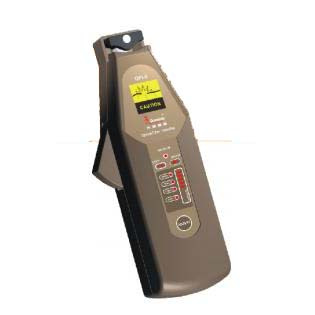
Demystifying the Fiber Identifier: Unveiling the Secrets of Light Measurement
Specialized equipment used to measure the strength of light signals in optical fibers is known as an optical power meter. Optical power meter measures optical power quantitatively in quantities such as watts (W) or decibels (dBm), providing vital insights into the performance and health of optical networks.
Operation and components:
Optical power meters are made up of a photodetector, which transforms light into electrical signals, and a display unit, which displays the measured power. The wavelength range of the light signals to be monitored determines the photodetector, which is often a silicon or indium gallium arsenide diode.
Optical power meters can measure wavelengths ranging from visible light to infrared, encompassing the most widely used wavelengths in fiber optic communication systems. Some sophisticated versions additionally have replaceable detectors, which allow users to adapt to varied wavelength ranges.
Optical Power Meter Applications:
Installation and upkeep: Optical power meters are essential during the installation and maintenance of fiber optic networks for evaluating signal strength, assuring proper splicing and connectorization, and resolving network faults. They assist technicians in identifying power losses or abnormal power levels, allowing them to take remedial action as soon as possible. Optical light source is also of great use.
Network Monitoring: In live optical networks, continual monitoring of optical power levels is required to identify signal deterioration, fiber breakage, and other abnormalities that might influence overall network performance. Optical power meters monitor power in real-time, assisting network operators in identifying possible faults and taking proactive actions to ensure network integrity.
Choosing an Optical Power Meter:
Several considerations should be addressed while choosing an optical power meter:
Power Measurement Range: Choose a power meter that can manage a wide range of power levels, accommodating both high and low power signals seen in various fiber optic systems.
Accuracy and Resolution: To guarantee exact measurements, look for a power meter with good accuracy and resolution. The resolution of an instrument defines the lowest observable power change, whereas accuracy represents its overall dependability.
Features and connectivity: Consider the power meter's connectivity choices, such as USB, Bluetooth, or Wi-Fi, which can help with data transmission and remote control. Data logging, wavelength identification, and auto-calibration are all features that can improve usability. You can buy fiber identifier online.

Follow our Facebook and Twitter for more information about our product.
#Fiber Identifier#Optical Light Source#Optical Power Meter#Visual Fault Locator#Fiber Interferometer
2 notes
·
View notes
Last Seen Blogs

allyjadeee
patrick batemans gf 🧸

diaranz-blog
Neko Girl

okhazza
tonight let's get some

o-the-mts
Portals of Discovery

shy-violet-soul
Still Wishing On Stars