#valve cotters
Explore tagged Tumblr posts
Visit Tumblr Blog
Explore Tumblr blogs with no restrictions, modern design and the best experience.
Last Seen Tumblr Blogs


Fun Fact
Mobile Tumblr US users spend an average of 4.04 minutes per session on the app.
Text
transforming soffits reorganizing keys formalizing immersion joints justifying kick extractors advising aggregates managing elbows recasting connectors achieving aluminum trowels officiating disks exhibiting absolute spigots progressing coil hydrants jerry-building reflectors informing casters inventing rubber hoists performing wrenches judging chalk adapters upgrading ignition paths
regrowing flashing recommending ratchets approving barriers sweeping impact fillers sewing mirrors detailing collectors enforcing measures distributing systems presenting plugs interwinding registers piloting ash diffusers gathering cranks supplying eave pockets undertaking scroll stops accelerating straps designing fittings protecting diamond boilers logging downspouts correlating shingles uniting mallets qualifying electrostatic lifts sharing clamps obtaining circular fluids ranking foundation gauges sensing miter brackets originating space networks translating drills regulating guards selecting gable padding utilizing pellet dowels reconciling artifacts altering pulleys shedding space filters determining vents representing mortar remaking flash rakers supporting funnels typecasting rotary chocks expressing junctures resetting auxiliary vises professing strip treads inlaying matter trowels questioning drivers forming edge fittings sketching blanks overshooting spark breakers rewriting controls playing tunnels inventorying buttons enduring joint handles effecting ratchet bibbs unwinding couplings forsaking vapor conduits defining sockets calculating heaters raising grids administering tiles measuring resources installing ignition remotes extracting corners manufacturing ventilators delegating consoles treating mounting stones enacting jig deflectors intensifying alleys improvising cargo pinpointing bobs prescribing arc masonry structuring metal chucks symbolizing lathes activating plumb kits adapting coatings fixing channels expediting cordage planning compressors enlisting hangers restructuring keyhole augers shearing ridge hardware collecting reciprocating bolts maintaining corrugated dimmers whetting hole collars conducting mandrels comparing assets compiling sealants completing paths composing equivocation wheels computing dampers conceiving electrostatic treatment ordering cotter grates organizing ties orienting ladders exceeding materials targeting thermocouples demonstrating emery stock expanding latch bases training wardrobe adhesives overcomming[sic] fasteners streamlining storm anchors navigating springs perfecting turnbuckles verifying gate pegs arbitrating arithmetic lifts negotiating outlets normalizing strips building surface foggers checking key torches knitting grinders mowing planers offsetting stencils acquiring bulbs adopting rivets observing avenues ascertaining coaxial grommets slinging wing winches instituting circuit generators instructing wicks integrating pry shutters interpreting immersion lumber clarifying coils classifying wood bits closing cogs cataloging matter strips charting holders conceptualizing push terminals stimulating supports overthrowing shaft spacers quick-freezing connectors unbinding ground hooks analyzing eyes anticipating gateways controlling proposition rollers converting power angles coordinating staples correcting benders counseling joist gaskets recording gutter pipes recruiting drains rehabilitating rafter tubes reinforcing washers reporting guard valves naming freize sprues nominating rings noting straps doubling nailers drafting circuit hoses dramatizing flanges splitting framing compounds refitting stems interweaving patch unions placing sillcocks sorting slot threads securing mode cutters diverting catharsis plates procuring load thresholds transferring syllogism twine directing switch nuts referring time spools diagnosing knobs discovering locks dispensing hinges displaying hasps resending arc binders retreading grooves retrofitting aesthetics portals seeking stocks shrinking wormholes assembling blocks assessing divers attaining lug boxes auditing nescience passages conserving strikes constructing braces contracting saw catches serving installation irons recognizing fluxes consolidating fuse calipers mapping shims reviewing chop groovers scheduling lag drives simplifying hoists engineering levels enhancing tack hollows establishing finishing blocks
21 notes
·
View notes
Text
Different Types of Monel Fasteners
Monel Fasteners are high-performance fastening components made from Monel alloys, primarily Monel 400 and Monel K500. Known for their exceptional resistance to corrosion, especially in marine and chemical environments, Monel fasteners are widely used in industries such as marine engineering, chemical processing, aerospace, and oil & gas.
In this blog, we will explore the various types of Monel fasteners, their features, applications, and benefits.
What is Monel?
Monel is a group of nickel alloys, mainly composed of nickel (up to 67%) and copper, with small amounts of iron, manganese, carbon, and silicon. The most commonly used Monel grades include:
Monel 400 – offers excellent corrosion resistance and high strength.
Monel K500 – provides higher strength and hardness due to added aluminum and titanium.
Key Properties of Monel Fasteners
Excellent resistance to seawater, acids, and alkalis.
High strength and toughness.
Superior resistance to corrosion cracking and pitting.
Performs well in high-temperature environments.
Non-magnetic in annealed condition.
Types of Monel Fasteners
Below are the most common types of Monel fasteners used across industries:
1. Monel Bolts
Monel bolts are used for securely fastening materials in highly corrosive environments. These include:
Hex Head Bolts
Heavy Hex Bolts
Socket Head Cap Screws
U-Bolts
Anchor Bolts
Carriage Bolts
Applications: Offshore platforms, marine vessels, pumps, heat exchangers.
2. Monel Nuts
Monel nuts pair with bolts and threaded fasteners. Types include:
Hex Nuts
Heavy Hex Nuts
Lock Nuts
Cap Nuts
Flange Nuts
Wing Nuts
Applications: Chemical plants, pressure vessels, shipbuilding.
3. Monel Screws
Monel screws offer secure fastening with excellent corrosion resistance.
Machine Screws
Self-Tapping Screws
Wood Screws
Socket Set Screws
Sheet Metal Screws
Applications: Aerospace assemblies, instrumentation, defense equipment.
4. Monel Washers
Washers distribute the load of fasteners and protect surfaces.
Flat Washers
Spring Washers
Lock Washers
Fender Washers
Sealing Washers
Applications: High-pressure equipment, marine applications, flanged joints.
5. Monel Studs
Studs are threaded rods used where full thread engagement is necessary.
Fully Threaded Studs
Double End Studs
Tap End Studs
Applications: Heat exchangers, chemical reactors, turbines.
6. Monel Threaded Rods
Threaded rods are ideal for anchoring and structural applications.
Applications: Marine construction, oil rigs, bridge building.
7. Monel Pins
Pins offer precise alignment and fastening in assemblies.
Dowel Pins
Taper Pins
Groove Pins
Split Pins (Cotter Pins)
Applications: Valves, pumps, motors, marine equipment.
Monel Grades Used in Fasteners
✔️ Monel 400 (UNS N04400)
Composition: ~67% Nickel, 30% Copper
Excellent resistance to seawater and acidic environments.
Used in marine and chemical processing.
✔️ Monel K500 (UNS N05500)
Precipitation-hardened alloy.
Higher strength than Monel 400.
Used in pump shafts, oil well tools, and high-torque fasteners.
Industries Using Monel Fasteners
Marine & Shipbuilding
Aerospace
Oil & Gas
Chemical & Petrochemical
Power Generation
Nuclear Industry
Advantages of Monel Fasteners
Long service life even in aggressive environments.
Reduced maintenance cost due to corrosion resistance.
Reliable performance under high mechanical stress.
Excellent for both fresh and saltwater exposure.
Ananka Group – Trusted Monel Fasteners Manufacturer in India
At Ananka Group, we are a leading Monel fasteners manufacturer, supplier, and exporter based in India, delivering premium quality products globally. We provide fasteners in various types, sizes, and Monel grades with international standards such as ASTM, ASME, DIN, and ISO.
Why Choose Us?
In-house manufacturing and quality control.
Wide inventory of Monel 400 and K500 fasteners.
Worldwide shipping and timely delivery.
Custom sizes and coatings available on request.
Standard Specifications
Standard
Description
ASTM B164
For Monel 400 Rods, Bars, and Wire
ASTM B865
For Monel K500 Rods and Bars
ASME SB-164 / SB-865
Boiler and Pressure Vessel Code
DIN / ISO / JIS / BS / EN
Metric Standards for International Use
FAQs
Q1. Are Monel fasteners better than stainless steel? A: Monel offers superior corrosion resistance in marine and acidic environments compared to stainless steel.
Q2. What is the temperature range for Monel fasteners? A: Monel fasteners can typically operate from sub-zero temperatures up to 480°C (900°F), depending on the grade.
Q3. Is Monel magnetic? A: Monel 400 is non-magnetic in the annealed condition, making it ideal for sensitive applications.
Q4. What are the common coatings for Monel fasteners? A: Monel fasteners are usually used without coatings due to their inherent corrosion resistance but can be passivated or coated if required.
Q5. Can Monel fasteners be welded? A: Yes, Monel can be welded using standard welding practices for nickel alloys, but it requires expertise to prevent cracking.
Conclusion
Monel fasteners are a premium choice for demanding applications where corrosion resistance, mechanical strength, and longevity are non-negotiable. From bolts and nuts to studs and washers, Monel alloys like 400 and K500 provide exceptional performance in marine, chemical, and industrial settings.
If you're looking for high-quality Monel fasteners, Ananka Group is your go-to supplier. We offer a wide range of fasteners in various sizes, grades, and finishes to meet your exact specifications.
#ananka#anankafasteners#fasteners#fastenersmanufacturer#monel#monelfasteners#typesofmonel#monelk500#linkedin#articles#blog#manufacturer#supplier#mumbai
0 notes
Link
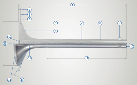
TAEVision 3D Mechanical Design Parts EngineParts Aftermarket @msmotorservice MSMotorservice TRW Automotive KS Kolbenschmidt GmbH Valves ValveTrain ValveGuides ValveCotters ValveSealInserts ValveControlElements ▸ TAEVision Engineering on Pinterest ▸ TAEVision Engineering on Google Photos ▸ TRW Automotive - Valves and Valve Accessories

Valves - Dimensions and Technical Terms
1 Total length = L 2 Total valve head thickness 3 Seat height 4 Height of valve seat face 5 Seat armouring (optional) 6 Valve head 7 Skirt diameter = d 8 Valve stem 9 Groove area 10 End face of stem (hardened) 11 Grinding length 12 Throat 13 Valve seat angle = α 14 Head surface 15 Head diameter = D 16 Calotte
Data 187 - Oct 24, 2021
#TAEVision#engineering#3d#mechanicaldesign#parts#engineparts#aftermarket#MSMotorservice#TRW Automotive#KS Kolbenschmidt GmbH#valves#valve train#ValveTrain#ValveGuides#valve guides#ValveCotters#valve cotters#ValveSealInserts#valve seal inserts#ValveControlElements#valve control elements
1 note
·
View note
Photo

2004 Ducati 749R
After an absence of three years, Ducati Corse re-entered the World Supersport Championship for the 2004 season. It was a tentative entry, with only Lorenzo Lanzi riding the factory 749R. The short-stroke 749R was the most advanced production bike yet offered by Ducati, and for racing the power was increased to 140 horsepower at 13,000 rpm. The bike was extremely fast, with Lanzi timed at 292 km/h at Monza, and he finished fifth in the 2004 World Supersport Championship. David Muscat also won the French Supersport Championship on a 749R, and Michael Laverty finished second in the British Supersport series on a similar machine.
Based on Pierre Terblanche’s 2003 999, the 749R was Ducati’s most exciting 2004 model. A real racer for the street, it was the most technically advanced production bike ever offered by Ducati up to that time. Powering the 749R was a new short-stroke version of the Testastretta motor. The 94x54mm motor displaced 749.5cc, and with a 12.7:1 compression ratio produced 118 horsepower at 10,250 rpm. The pressure die-cast crankcases were deeper sump, the pistons forged Asso, with unmachined cylinder head ports to allow modification for racing. As the top-end assembly was identical to other 749s, the shorter stroke required longer titanium Pankl con-rods (128.5mm). These also had the advantage of limiting piston lateral thrust against the cylinder. The camshafts were higher lift (13mm intake and 11.5mm exhaust), with extremely steep ramps, and valves 39.5 and 32mm. The 749R was the first production Ducati with titanium valves (by Del West) as standard equipment, and because titanium has high surface abrasion, the valve seats and valve guides were Berilbronz.
While the included valve angle was unchanged at 27°, the closing valve stem adjuster set-up was the same as on the factory Superbike engines, with two titanium cotters instead of the usual half-rings. The desmodromic rocker arm acted on the adjuster to close the valve, its thickness determining the clearance. The valve stems were also narrower (6mm) than on other Testastrettas. The crankshaft was also designed for racing, with smaller flywheels, the cross-section tapered and grooved to reduce internal friction. To minimise timing belt failure due to excessive heat build up, a cooling duct was installed on the rear carbon-fibre belt cover. The clutch was a slipper clutch type, the pressure plate with cylindrical clutch springs and a composite drum with inclined surfaces activated during back torque. The valve covers were magnesium.
Unlike the regular gear teeth on the 749 and 749S, a phonic wheel was machined on the outer rim of the camshaft drive gear, coupled to a magnetic induction sensor, to generate the rpm signal and phase for the engine management. This provided a clearer electronic signal at higher rpm. For racing, another sensor was installed for rpm, coupled to the flywheel with four teeth at 90° intervals. The single Magneti Marelli IWPR2 injector per cylinder, mounted above the throttle inside the 54mm throttle body, was not the single-hole injector found on other Testastrettas, but a 12-hole racing type. The ECU was an IAW 5AM.
The chassis included a new aluminium swingarm, similar to the 999 F03 World Superbike racer. The pivot area was cast aluminium, while the arms were box sectioned, the left side featuring lower reinforcement. It also incorporated Superbike type chain adjustment sliders instead of a conventional cam mechanism. Also new was the rear suspension linkage, with FLAT progression, including a different spring and shorter stroke (from 71 to 56mm) for the Öhlins shock absorber. The rocker arm was positioned above the shock absorber with a revised push-rod mount. As on the 999R, the 43mm Öhlins front fork allowed for radial Brembo brake calipers, and the forged aluminium wheels featured five “Y” spokes with 10 anchor points on the inside of the rim. For racing, the fork offset could also be altered via a pin. There were two settings, 30 and 36mm, but this feature was disabled for street use. As it was such a high specification model Ducati only produced around 1000 749Rs, as required for FIM homologation for 2004 and 2005.
17 notes
·
View notes
Text
A Bum Steer
Parts arrived! Time to put the steering in order on Sacrebleu! First, let’s get all the equipment out. Hydraulic jack, jack stands, tool cart. Pull Sacrebleu in front of the garage, line the jack up on the underside of the engine cradle and begin lifting the front end into the air. Oops, I don’t have the jack centered well enough, Sacrebleu is rocking a little three wheel motion. That’s not going to work. I lower the jack slowly, and try again. Ok, even with the mechanical advantage of the long lever, AND the hydraulic advantage, Sacrebleu is HEAVY! This time goes better, and both wheels slowly leave the ground. The jack shifts, rolling forward further under the car, as the pad of the jack pulls the frame along with each pump raising the car. Finally there’s enough clearance to get jack stands under the A arms, carefully positioning, then lowering the weight onto the stands. I leave the jack in place with some tension on it, as a safety measure. Now’s the time to capture video of the slop between the center link and the pitman arm, after a few false starts, I get enough video to create a gif with.
A quick examination of the fasteners leads me to go back in the garage and come out with the tools I didn’t grab before. A pair of needle nose pliers for the cotter pins through the castle nuts, a set of 3/8″ drive semi-deep impact sockets, and an electric 3/8″ drive ratchet. I start with the pitman arm, using the pliers to pry the cotter pin off the nut before straightening the pin and pulling it back through the nut. I try to get the ratchet on the nut, but there’s not enough room. I go to the tool cart, and grab a flex head 3/8″ drive ratchet, and with a bit of oomph, the nut comes loose. I repeat the process three more times, at the idler arm, and both inner tie rod ends. All the fasteners are off, the only thing holding the center link in now is the friction of the press fit of the tapered shafts for the link itself and the inner tie rod ends. I experimentally give the ends of the tie rod end a few taps with a maul, with little success. I hit it a little harder, and think I’m getting somewhere. I go after the end of it with a will, and end up having made no progress, and my muscles are exhausted. I experiment on the other tie rod end, with a similar lack of success. I pause, think for a moment, and with a bit of dread, try to thread a castle nut onto the inner tie rod…nope. Ain’t happenin’, bro. I’ve mushroomed them, and am going to have to replace the tie rod ends on both sides. Greaaaaat. This still doesn’t solve how I’m going to get the center link loose from the pitman arm, idler arm, and inner tie rod ends. The only thing that comes to mind is buying a pickle fork. It’s a heavy, drop-forged tool that splits the press fit pieces together with judicious application of a maul. Ok, fine. Off to the auto parts store I go, it’s a mile up the road. First, I wash up and dust off, brushing as much of the dirt and dust from my clothes before hopping in the car. That chore finished, I find myself standing in the parts store, facing the counter, being helped by an associate. Oh! The gas cap on Sacrebleu needs to be replaced, I can order one while I’m here. While doing that, I notice that the parts store has a tool rental program, where you “buy” the tool, and if you return it within 48 hours, they refund the money. The pickle fork is part of their tool loan program, so I buy/borrow it and head home. Once I’m home, I waste no time crawling back under Sacrebleu, and in less than 5 minutes, I have the center link freed from both the pitman and idler arms. That just leaves the inner tie rod ends. I position the pickle fork, but there’s no room to get any real force on the end of the fork. I suppose it would be fair to say I’m in a bit of a pickle. A few moments of consideration, and I’m carefully lowering the jack, bringing all the weight of the front end of the car onto the jack stands. The stands take the load, I take the jack and position the lifting pad under the pickle fork end. Then, I start pumping the jack, slowly pressing it against the end of the fork, letting the weight of the front end bear on the fork and the joint. Suddenly, the parts come loose, with a bit of a jump and a jerk. Success! Triumph! Only one more inner tie rod end remains to be separated, and the center link will be free! I manhandle the jack over to the other side, line up the fork, and repeat the process. Oho, this one isn’t going as smoothly as the first, and I end up lifting the front end of the car BY the fork AT the joint, OFF the jack stand. Yeah, that’s not safe. I reposition, and try again, with the same result, but with the added bonus of Sacrebleu trying to shift off the jack stand laterally! Ok, what about hitting the joint while it’s under tension? Sure, why not? What could go wrong with hitting the end of the tie rod end with a thousand or more pounds bearing on it. Um….yeah, no. I lower the jack, free the fork, and give the tie rod end stud a few good whacks. When I get everything repositioned, the stud pops free of the center link, and the link is now loose at all four points. I pull the tie rod end studs free, leaving the center link held in place by the idler and pitman arms. A bit more wrangling, a bit of persuasion with the maul, and the center link is free!
Installation is the reverse of removal. (Again, iykyk)
Hanging the new center link from the pitman and idler arm is easy, I run the castle nuts down just to hold it in place. I’m done for the evening, because I need inner tie rod ends. This is a good time to take the pickle fork back to the parts store, and see about ordering parts. Checking their online portal, it shows the value line (Read: Cheap) steering components available next day, and the quality ones not available next day. Driving back to the parts store with the tool and receipt, I work with the person at the counter, order a new locking gas cap, and the value line inner tie rod ends. That’s it for the day, there’s nothing more to be done.
*12 hours later*
I call the shop doing the work and speak with H, he recommends replacing the rest of the steering components, adjusting sleeves and outer tie rod ends. I decide to get the adjusting sleeves and leave the outer tie rod ends alone, that way I don’t have to borrow the pickle fork again. Midday, I pick up the parts from a store near work, top quality stuff from my preferred parts company. The company discount saves me $45, about 35% off retail. Nice. The remainder of the work day passes, soon I find myself home, new parts ready to be installed. I still need to remove the old inner tie rod ends and adjusting sleeves, and the passenger side seems a bit resistant to coming free, but with a bit of leverage, working smarter, not harder, I free the inner tie rod end and adjusting sleeve all as one assembly. The new hardware is laid out, ready to be installed, I take a minute to get some anti-seize lubricant on the threads of the sleeves, to help prevent galling. By some miracle, anti-seize ends up only on the threads. I run the new tie rod end to the sleeve, match it up for approximate length to the one I just removed, tighten the clamp nut, and begin installing it in the car, threading the adjusting sleeve onto the outer tie rod end, down to where the previous sleeve had been threaded. A little bit of fiddling gets the tie rod end stud lined up with the center link, and the castle nut is threaded on loosely. Repeat for the driver’s side, and it’s time to torque to spec. Climbing from under the car, I go in the house, wash up, and grab the factory chassis service manual for the car. A few minutes later, I have the torque specs for the fasteners. 30-50lb-ft for all but the pitman arm, 30-40lb-ft for the pitman arm. I decide to go 35lb-ft for the pitman arm and 40lb-ft for the rest. Applying the torque wrench, I go around and tighten everything to spec, then check it. Once everything is torqued, I only have to tighten one castle nut to line up the groove for the cotter pin, sweet! I decide to check the steering, but this time, there’s NO movement. I can’t shift anything, everything is right and tight! For the last time, I climb out from under the car, clear all the tools, and position the jack on the engine cradle/crossmember, this time to lift it off the jack stands. The front end rises, I snag the jack stands, pulling them clear. Carefully, watching the car closely, I open the pressure relief valve on the jack, slowly. Sacrebleu returns to all 4 wheels on the ground, and with relief, I pull the jack away. All that’s left is putting away the tools and equipment, and washing up. A non-event, a necessity nonetheless.
The following morning, driving Sacrebleu to the shop, I’m thrilled with the change in steering. Sacrebleu no longer darts as though she’s trying to kill me. Once I arrive at the repair shop, H puts it up on the alignment rack, lubricates all the fittings I forgot to do, sets the steering wheel straight, and pronounces my work good.
#16#sacrebleu#boattail#boat tail#riviera#buickriviera#buick#buick riviera#72 Buick#72Buick#rivierags#72riviera#fastwithclass#70scars#70s cars#gscars#stage1#buick455#bigblockbuick#buickbigblock#3rdgenriviera#3rdgen#steering#centerlink#center link
3 notes
·
View notes
Text
How to Replace a Gas Grill Burner

This straightforward undertaking will make them cook with gas again in the blink of an eye
Most gas flame broils in this nation get kicked to the control following a couple of brief long periods of administration. What's more, a wore out gas barbecue burner is a typical guilty party. Rather than dropping a few hundred dollars on a fresh out of the plastic new barbecue, you can inhale new life into the one you have for $20 or less with this straightforward fix.
The burner is the piece of the barbecue that creates the fire. Contingent upon the size of the flame broil, there may be two to 10 burners inside. It's a smart thought to examine the burners a couple of times each year for indications of erosion. Bug catching networks are something else to look for, since the critters like to construct homes and lay eggs inside the burners, obstructing the progression of gas.
For the time being, how about we accept that you're past the purpose of preventive measures, and your messed up gas barbecue burner needs supplanting. Here's the manner by which to take care of business in five basic advances.
Stage 1
On the off chance that you can't accepting a substitution gas barbecue burner from the nearby home place, check the producer's site. You'll require the barbecue model number, which is typically situated on the back or underside of the truck. Single burners start around $10; they're regularly sold in multipacks, ideal on the off chance that you have to supplant various burners.
Stage 2
When you have your substitution gas barbecue burner, you're prepared to eliminate the old burner. Start by detaching the flame broil from the propane or petroleum gas line. For good measure, ensure all the control handles are in the off position. At that point lift out the cooking grates and flavorizer bars, otherwise called heat plates.
Stage 3
The burner will currently be completely noticeable and available. Despite the fact that we discovered some variety in gathering from one brand to straightaway, by and large the gas barbecue burner is held set up at the front and back with equipment.
In the barbecue included in this video (a recently tried model from Char-Broil that is a substitute for exhibit purposes) the burner is made sure about with a couple of cotter sticks; yours strength use screws or another sort of latch.
In the wake of eliminating the pins by hand, we lifted a vestige tube off the burner. Next we separated the burner from the terminal, which gives the flash when lighting the flame broil, by prying off a clasp with a little flathead screwdriver. By then, the burner delivered unreservedly from the terminal and valve opening. Be cautious during this progression not to break or in any case bargain the clay encasing around the cathode, or it could wind up shorting out.
Stage 4
To introduce the new gas barbecue burner you just need to switch similar advances. For our situation, that implied reconnecting the burner to the cathode and valve opening, setting the burner onto its firebox upholds, reinstalling the vestige section, and slipping the cotter sticks once again into the right spot.
Stage 5
It's a smart thought to test the burner prior to assembling the flame broil back. To begin with, reconnect the gas flexibly line and attempt to light the burner. On the off chance that there's a smell of gas or the blazes are lopsided, turn the barbecue off promptly and allude to the investigating segment of your manual. The burner and valve may not be appropriately drawn in or there might be an issue with the valve controller. After all other options have been exhausted, have a go at calling the maker's client service line.
On the off chance that the gas barbecue burner lights effectively and the fire goes easily from low to high with a turn of the handle, you're prepared to start up the flame broil seriously.
On the off chance that your gas flame broil has some significant virus spots, or isn't working in any way, some awful burners are the most probable reason. Here's the means by which to trade in some new ones and make that old barbecue like new once more. In this video from the Consumer Reports YouTube channel, Home Editor Dan Diclerico tells the best way to eliminate and supplant an old gas burner in a couple of simple advances:
Detach the propane tank and mood killer all the burners.
Eliminate flame broil grates and flavorizer/flavor bars (the A-formed metal braces that shield your burners from oil drippings). You should now observe your burners.
Pull the cotter pins holding the old burner set up.
Lift the remainder tube so it's not associated with the old burner any longer.
Pop the burner out of the metal cinch with a flathead screwdriver (this ought to be the exact opposite thing interfacing the old burner to the flame broil) Learn more.
1 note
·
View note
Text
Cotter Valve Kuku Klep KND180 KND190 KND220 KND250 Original
Kuku Klep Kubota KND180 KND190 KND220 KND250 Original
0 notes
Text
Crack Maintenance Trailer Package
For some, a reminder an hour before the scheduled time is all one would want, whereas for others, to plan out issues, 2-day advance notice may be required. An email reminder shall be triggered to you accordingly. Knowing what causes them means you’ll need to verify for any loose elements banging together. If you reduce the inner noise of the car, you'll be able to hear the place the problems stem from as you make varied maneuvers.
Thoroughly clean the locking mechanism each six months or 60,000 miles. Use a plug and socket brush with water to clean connectors every six months, or extra frequently in highly corrosive environments. Among the various maintenance trailer gadgets in its collection of Qwik Tech Tips, Phillips Industries covers combating electrical corrosion. Check that tender springs, clamps, pogo sticks, or slider bars are installed and performance correctly.
Before taking off with every load, examine the heavy-haul trailer, checking that brakes and tires are in good situation. Also, ensure tires are correctly inflated to the best psi, and confirm that hydraulic hoses are free from cracks or damage. If you’re working a detachable or rear-load mannequin, be positive to properly preserve hydraulic strain – even on self-contained and wet lines. One of the commonest indicators of something incorrect with a trailer is unusual clicking or rattling sounds.
Save in costs long-term with element lifecycle management, aggressive labor charges and national components accounts. Trailer jacks are notorious for seizing up over the winter. A small hole drilled about 4” down from the handle will allow you to get some lubricant on the threaded shaft, the seizing of which is the most maintenance trailer typical problem. Alternatively, the brakes will apply on your first stop and will not launch resulting within the brakes dragging. Since 2008, Highliner trailers have been constructed with a chrome steel sleeve put in beneath the seal.
In some cases, the connector may be loose or improperly hooked up. There could be some wires that want tightening or crimping. If this basic troubleshooting doesn’t clear up the problem, then suspect a severed trailer wire or corrosion in some unspecified time within the future. Basically, trailer maintenance tasks are the identical regardless of the sort and size of trailer. However, larger models would possibly come with extra elements in addition to more advanced mechanics. Starters might be confused where to begin and tips on how to proceed with trailer maintenance.
It’s quite frequent to see grease in liquid type around the front and rear of the wheels. This is because because the grease turns into more liquid it might possibly often find its well past seals in the maintenance trailer bearings. If you set the trailer in the water whilst hot, the water will discover its means in to the bearings. At Wachs we’re usually requested, what's the best automobile platform to pick for a valve maintenance system?
Make sure the latch stays in place when in use and that it stays locked with cotter pins. Don’t neglect to connect the chains to the secondary couplings, either. When replacing a ring, the load ranking must match or exceed the GVWR of the trailer. Cargo trailer door ramps may have cables and is derived to help in opening and shutting. A good indicator of cracks, stress or fatigue could be rust.
We absolutely perceive your needs and can do our greatest in serving to you make the perfect choice. Taking care of your own maintenance could be a cost-saving answer for sure companies, corresponding to people who have their very own in-house service outlets. This is particularly necessary to recollect after a long winter when you want to re-fresh your trailering skills. You'll at all times need to give your boat trailer an excellent once-over before hitting the highway, to keep away from any surprises.
0 notes
Link
6136-42-4520 Supap tırnağı S6D105 Motor KOMATSU / 6136-42-4520 Cotter valve S6D105 Engine KOMATSU
0 notes
Text
Control Valve
This valve controls the expulsion of oil from the spring side of the second gear band servo piston at speeds in the region of 60 km/h. The time period for oil to exhaust then depends upon the governor pressure varying the effective exhaust port restriction. Line pressure oil from the spring side of the second gear band servo piston passes through a passage leading to the 3–2 kickdown valve annular groove and from there to the 2–3 shift valve annular groove. Here some oil exhausts out from a fixed restriction while the remainder passes via a passage to the 3–2 control valve. As the vehicle speed approaches 60 km/h the governor pressure rises sufficiently to force back the 3–2 control valve piston, thus causing the wasted (reduced diameter) part of the control valve to complete the exhaustion of oil.
Valves control the gas flowing into and out of the engine cylinder. The camshaft and valve spring make up the mechanism that lifts and closes the valves. The valve train determines the performance characteristics of four-stroke-cycle engines.
There are two types of valve, inlet and exhaust. Figure 6.1 shows an exhaust valve. An inlet valve has a similar form. The commonly used poppet valve1 is mushroom-shaped. Figure 6.2 illustrates the parts of the valve. A cotter (not shown in Fig. 6.2) which fixes the valve spring retainer to the valve, is inserted into the cotter groove.Alumina valves and seats
corrosion resistant control valve come in many forms: butterfly valve, ball and seat valve, disk-valve, piston-sleeve metering valve, and dart valve, to name but a few. Alumina has been used in many industrial valves. Water faucet valves of the standard disk-on-disk configuration are very common and are discussed in Section 12.2.8. Since they share almost all the same features of pump rotary valves.
Dart valve plugs and seats are a fluid-flow-control component. When used in the mineral processing industry, or in other industries where slurries, or corrosive liquids, or corrosive slurries are flowing, these valve/plug systems need to be highly wear resistant, especially the plug which can be particularly exposed to the flow of the erosive/corrosive fluids. An example of a dart valve and plug is shown in Fig. 12.17. Alumina valves are an increasingly common technology in general.
One revolution of the camshaft gives the amount of valve lift shown in Fig. 6.3. The valve stem moves in the valve guide and also revolves slowly around the stem. The revolving torque is generated by the expansion and contraction of the valve spring.
An engine basically needs one inlet valve and one exhaust valve per cylinder but most modern engines use four valves per cylinder. This multi-valve configuration raises power output, because the increased inlet area gives a higher volume of gas flow. Contemporary five-valve engines use three inlet valves and two exhaust valves to increase trapping efficiency at medium revolutions.
Figure 6.4 summarizes the functions of the valve. The shape of the neck, from the crown to the valve stem, ensures that the gas runs smoothly. The valve typically receives an acceleration of 2000 m/s2 under high temperatures. Valves must be of light weight to allow the rapid reciprocating motion.
With the single seated control valve lowered, the hydraulic pump is applied to bring the bottom plate of the mould to the lower limit. The separator is then lowered into the mould and fed with the shell and the inner core materials. The vibrator is switched on for 5 s to consolidate the content. The space created by consolidation is topped up. The vibrator is switched on again while the separator is extracted from the moulds. The top of the content of mould is flattened, and the mould lid closed and clamped. With the single seated balanced control valve raised, the hydraulic pump is engaged to stress the content to the desired compaction pressure, which was readable on the gauge. The mould lid is opened and with the control valve raised, the block is ejected from the mould.
Typical specimens of hollow SCEB produced with the mechanical kit are shown in Fig. 13.8. The two holes reduced the overall weight of block by 24%. It is also anticipated that the hollowed nature of the block will accommodate any expansion of the inner core material.
Active or passive valves control the flow of samples and reagent through the different steps. Passive valves are able to control fluid movement in a limited way, for example, by allowing flow in one direction through a channel but not in the other one as described above On the other hand, active valves need to be actuated externally using a smart control strategy that typically makes use of sensors to have feedback (Schumacher et al., 2012). Actuation of these valves is very often performed by electrical means, for example, by having a current flow through a copper line and then heating a chamber filled with air that expands and deflects a flexible membrane, which closes a microfluidic channel. Sometimes the deformation of such a membrane is directly performed by using pressurized air coming from an external source, making the valve actuation purely pneumatic instead of electrothermal.
The open tank and multi hole single seated control valve arrangement (Fig. 4) used here together with the 3% cavitation criterion in Fig. 2 is considered to be an industry-based and reliable method for determination of NPSHR in the pump best efficiency region, ISO [4]. More elaborate closed vacuum tank arrangements are used by pump manufacturers to establish NPSHR-curves for water. The measured NPSHR-values obtained here for water (Fig. 5) were about 10% larger than values from the GIW-pump curves. This means that the slurry NPSHR-results in Fig. 5 were about 1.5 times the water values from the pump curves. The scatter may represent the increased cavitation intensity of flow disturbances in an open tank system when compared to a closed tank arrangement.
Experimental closed tank results for sands with average particle sizes of 0.18 and 0.5 mm in pumps with impeller diameters of 0.35 and 0.6 m, respectively, were reported by Herbich [5]. Slurry densities were up to about 1400 kg/m3. It was found that the NPSHR-values (expressed in m of slurry) were similar to the water values, independent of the slurry density. Similar results were also reported by Herbich [5] and Ladouani et al. [6] for non-settling clay-silt slurries with densities of up to 1300 kg/m3 in pumps with impeller diametres less than 0.275 m. Ladouani et al. [6] used an open-tank loop arrangement. Detailed inspection of their data indicates that the independence of the slurry density on NPSHR was limited to flow rates smaller than about 70% of the best efficiency point (BEP). With larger flow rates, NPSHR increased with increasing slurry densities, giving values from 1 to about 2 times the water values in the BEP-region.
The results obtained here were for flow rates close to BEP. Field NPSHR results agreed reasonably well with the laboratory data for the same type of pump pumping phosphate (Fig. 1) at about 500 rpm for flow rates of about 75% of BEP, Addie et al. [7]. In practice, it is therefore reasonable to assume that the laboratory NPSHR-results obtained here are applicable for the flow rate region where most slurry pumps operate today (0.75 to 1.0 of BEP).
Balancing (Fig. 12.15(a and b)) With the compressed air passing to the brake actuator chambers, air pressure is built up beneath the upper and lower pistons. Eventually the upthrust created by this air pressure equals the downward spring force; the pistons and valve carrier lift and the inlet valves close, thus interrupting the compressed air supply to the brake actuators. At the same time, the exhaust valves remain closed. The valves are then in a balanced condition with equal force above an below the upper piston and with equal air pressure being held in both halves of the brake line circuits.
Pushing the treadle down still further applies an additional force on top of the graduating spring. There will be a corresponding increase in the air pressure delivered and a new point of balance will be reached.
Removing some of the effort on the foot treadle reduces the force on top of the graduating spring. The pistons and valve carrier will then lift due to the air pressure and piston return springs. When this occurs the inlet valves remain closed and the exhaust valves open to exhausting air pressure from the brake actuators until a state of balance is obtained at lower pressure.
Releasing brakes (Fig. 12.15(b)) Removing the driver's force from the treadle allows the upper and lower piston and the valve carrier to rise to the highest position. This initially causes the inlet/exhaust valves to close their inlet seats, but with further upward movement of the pistons and valve assembly both exhaust valves open. Air from both brake circuits will therefore quickly escape to the atmosphere thus fully releasing the brakes.
It’s difficult to obtain the flow of sequential valves due to lack of measurement data. The main steam is separated through the four valves and then enter into corresponding group of nozzles. The only flow data we can get from measurement is the main steam. Although there are various formulas to calculate the theoretical flow of valves, flow characteristics of valves are required to obtain the actual flow. However, the flow characteristics of sequential valves are not available through experiment. So a calculation method rely on operation data is necessary.
0 notes
Link
TAEVision 3D Mechanical Design Parts EngineParts Aftermarket @msmotorservice MSMotorservice TRW Automotive KS Kolbenschmidt GmbH Valves ValveTrain ValveGuides ValveCotters ValveSealInserts ValveControlElements ▸ TAEVision Engineering on Pinterest ▸ TAEVision Engineering on Google Photos ▸ TRW Automotive - Valves and Valve Accessories
Valves - Dimensions and Technical Terms
1 Total length = L 2 Total valve head thickness 3 Seat height 4 Height of valve seat face 5 Seat armouring (optional) 6 Valve head 7 Skirt diameter = d 8 Valve stem 9 Groove area 10 End face of stem (hardened) 11 Grinding length 12 Throat 13 Valve seat angle = α 14 Head surface 15 Head diameter = D 16 Calotte
Data 187 - Jul 08, 2021
#TAEVision#engineering#3d#mechanicaldesign#parts#engineparts#aftermarket#MSMotorservice#TRW Automotive#KS Kolbenschmidt GmbH#valves#valve train#ValveTrain#valve guides#ValveGuides#valve cotters#ValveCotters#valve seal inserts#ValveSealInserts#valve control elements#ValveControlElements
1 note
·
View note
Text
Brand new Katana fuel tanks now in stock on Suzuki Vintage Parts Programme

Brand new, genuine Katana fuel tanks are now in stock and available on Suzuki’s Vintage Parts Programme, after the Japanese firm remanufactured a limited run. With an RRP of £746.76 including VAT, the brand new fuel tanks fit GSX1100SD and GSX1000SZ Katanas and are finished in the glorious silver and adorned with the same red Suzuki lettering. Suzuki GB aftersales co-ordinator Tim Davies, said, “We’re really excited to have these new Katana fuel tanks in stock, in the UK, and that the factory have been able to reproduce this limited run. No one needs me to point out how iconic the Katana is and how they’re still so sought after, and we see so many restorations or custom builds based on the bike. Of course, over time, bikes left to stand can suffer from all sorts of problems with stale fuel or water and moisture in the tank, so being able to replace it completely for a brand new, genuine item is a great thing to be able to do for a bike that is 40-years-old.” Designed by Hans A. Muth and Target Design, the Katana was like nothing before it. It was a radical departure from current motorcycling fashion and was a sales success for Suzuki. Other parts still available for the Katana include centre stands, brake and clutch levers, clock surrounds, sprocket covers, con-rods, pistons, and piston rings, an array of gaskets, valves, cotters, seals, and springs, and even the carburettor intakes pipe rubbers. The new fuel tanks and other parts on the Vintage Parts Programme can be ordered through authorised Suzuki dealers. Find your nearest Suzuki dealer here. Find out more about the Vintage Parts Programme here. For more Suzuki GB news check out our dedicated page Suzuki GB News For more information on Suzuki Bikes GB visit bikes.suzuki.co.uk/bikes/ Follow us on social media: Instagram: @superbikenews Twitter: @sbknews Facebook: @superbikenews

SBN Directory - add your motorcycle related business here

Click here for more info on Arai Helmets

Click here for more info on Xena Security

Click here for more info and to buy Biker T-Shirts

Grid Girls UK If you would like to receive our headlines daily to your email inbox then sign up to our newsletter: Here Subscribe to our news channels: Here

Read the full article
#MotorcycleNews#Motorcycles#NewMotorcycleModels#Suzuki#SuzukiKatana#SuzukiMotorcycles#SuzukiVintagePartsProgramme
0 notes
Text
How a Top Model Makes Mechanical Drafting Courses Work
Mechanical drafting
Engineering language is expressed in drawing & drafting .Its a means of communicating with dimensions ,proportions , scale of machine or a building describing its details like the shape , size and section by a verbal or written language is very difficult henceforth Graphic language is used to express drawings .People who do these measured drawings are called as Draftsmen. Mechanical draftsman play a key role in the civil design industry .They do the 2d & 3d modelling of the buildings. They get well paid as a fresher and with experience.
Course Fees: 35000
Course Fees (NRI) : 1350
Scope & Career
Power plants
Petro Chemical Complex
Oil & gas need Piping Draftsman
Off shore Industry
Refinery
Industrial plants
Energy sector
Chemical process
EPC industry
Consulting engineers
Pharmaceutical industry
Project & Construction
Cement and Fertilizer
Syllabus
I. Mechanical draftsman Introduction:-
Free hand sketching.
Use of drawing instruments and materials.
Drawing conventional lines according to isi code. Folding of sheets.
Draw 1st & 3rd angle projection of points, lines, plain figures, solids & simple machine components
2d & 3d drafting.
II. Mechanical Drafting :Detailing
Draw different types of sectional views and dimensioning their drawings
Draw isometric oblique and perspective projection of simple objects
Draw inter-penetration curves and developed simple objects
Draw temp. Fasteners – screws threads, bolts, nuts, washers, locking devices
Machine screws, cap screws, studs, set screws, foundation bolts, circlips, keys, cotters, and pins
Draw types of rivets and riveted joints.
Use of important pattern maker’s tools, making of simple patterns, use of molding tools and preparation of simple mould
Use blacksmiths hand tool, forging of simple jobs
Use fitter hand tools and measuring instruments
Carry out simple operations on shaping, and milling machines
Carry out simple operation on lathe
Use of sheet metal work and tools, elementary knowledge of gas and gas welding.
Elementary knowledge of electrician trade and to be able to identify the different parts of i.c. engine
Prepare free hand sketches from exiting machine parts. Inking and colouring the drawing. Tracing a drawing on both tracing paper and cloth.
Draw details & assembly drawings of machine parts like coupling bearing, pulleys etc
III. Mechanical Drafting : Working Drawings
Prepare piping drawings, main line layout as done previously
Prepare working drawings of different types of gears.
Prepare details and assembly drawings of important machine parts and engine parts
Draw working drawings of jigs, fixtures, gauges, press tools
Draw welding drawings, use of welding symbols on drawings
Draw foundations drawings for machinery
Draw and sketch assembly drawing of bench drilling and slotting machines.
To prepare working drawing of machine parts and components independently taking sketches from the shop floor
Making working drawing of projects.
Familiarization with :
Is-1444(drg. Board)
Is-1360 (t-sqr.)
Is-1561(set sqr.)
Is-696 (code of engg.drg.)
Preparation of detailed drawings from assembly. Drawings of simple machine parts such as : tool post of shaping
IV. Mechanical draftsman software’s
Auto cad.
V. Live projects for Mechanical draftsman (2 nos)=
Mechanical drafting fixture for drilling hole.
Mechanical drafting of milling fixture.
Mechanical drafting of north light
Mechanical drafting of Valve
Training Features
Since 14 years.
Our mentors have 3 to 10 year industrial knowledge.
Senior lead engineers convert the candidates to junior engineers..
Live Chat with faculty.
Virtual class rooms.
Audio & Video tutorials.
Based upon real projects.
In Plant visit for candidates..
Hands on training on leading software.
Career counseling & guidance .
100 % job oriented training program.
Best placement records are maintained till now.
Dimensional Academy is one of the best distance education institutes in India for Mechanical drafting and fire fighting course. We provide online training, contact our study centers at Mumbai and Chennai to know more.
Are you looking for best academy of piping engineering course in india ? DIMENSIONAL ACADEMY was launched in the year 1999; we have completed 14 years of excellence with more than 100 editions in the class room version. We have crossed 25 online batches successfully. More than 10000 Design Engineers are created by us, who are working at high positions in diverse industries across the globe.
0 notes
Text
Keep the tractor working

Our 1950 Ford 8N tractor is finally purring like a kitten! A bunch of parts, trial and error, and swear words and she’s almost ready to do work. But, nothing ever is easy with this machine and so on to the next project. My goal is to keep the tractor working, doing what she was designed to do - be a reliable (70 year old) tool. Wasn't paying attention to the camera...sorry about the thumb...but she runs nicely now When we moved to our property we bought a 1950 Ford 8N that we planned to use mostly for mowing and perhaps eventually other fieldwork. We couldn’t afford a newer tractor with a front end loader, and the purchase included a dual-axle car trailer plus a number of implements, so we felt we got a good deal. Over time I’ve become more familiar with the machine and have seen where maintenance has been neglected over the years. Since purchasing it, I’ve repaired the hydraulic lift, which included scraping out the decades of gunked up hydraulic “fluid” and installing new piston and O-ring, lift cylinder, (and bent lift arm…). I’ve also repaired or replaced a number of components in the fuel and electrical system including the carburetor and distributor. This past winter I ended up taking the head off of the engine block and replaced the valves with newer adjustable valves. I cleaned the carbon from the accessible parts of the block, replaced the head with a new gasket and grade 5 bolts, and torqued to specs. The pistons and sleeves looked good enough so I decided not to replace them at this point.


Before and after the cleaning before replacing the valves Once I put all of the doo-dads back in place (technical term), I couldn’t get the engine to start. It would sputter, but wouldn’t run. I scratched my head and checked that it had all needed elements – fuel, air, spark and compression. Finally, after checking the Ford Dealer Mechanic Training Manual I figured it out – the timing was off. Following the manual, I got everything set correctly and she fired right up! There were a couple of mishaps though…oil flowed out of the filter canister and all over the shop floor…turns out a washer needed replacement. Once installed, I started her up and no more oil leak. But then, once the engine warmed up, coolant started spraying out from the radiator cap all over the shop. After letting the engine cool (and me cooling off after a few choice swear words) I saw that the lip on the radiator was bent, so the cap wasn’t sealing properly. I used a small pry bar and made a few modifications and presto – the cap fits snug and no more coolant leaks.
What Next?
Now that it’s Spring, there’s lots of mowing to get to and I hoped to hop on the 8N and hook up the mower. When I sat in the seat and tried to shift into gear, the clutch wouldn’t disengage so I couldn’t get into gear. I’ve tried a bunch of quick fixes to get it free, but so far it’s still stuck. (Lesson learned: wedge the clutch pedal down when stored.) Long story short, I’ve just ordered a new clutch kit and will replace the transmission shaft seal while I have the tractor “split.” I also decided to replace the axle seals that I noticed are worn out. This will give me the opportunity to finish the brake repair. I replaced the brakes and when I took the hubs off, they were deeply grooved so brake shoes weren’t making firm contact. I have new hubs, so while I replace the axle seals, I’ll reassemble with the new hubs. While I wait for parts, I decided to revisit the hydraulics and adjust them to spec. One thing I neglected when I replaced the lift cylinder was the cam follower pin. Let me tell you that it was a royal PITA! A while ago I bought a jig from Zane Sherman that helps line up and adjust the lift linkage. The kit came with a new cam follower pin and so I figured I'd just take it all apart, replace the pin, and then adjust to specs. Of course, it was a longer process than expected, and involved removing various parts to be able to get to the cam follower pin and get it replaced. Hours later, its replaced. I will adjust it and reassemble once I get the cotter pins I need that I didn't have on hand. Oh well. Bright side is that once complete, I'll have an adjusted lift that will have working position control and draft control should I need it! (if I decide to use the moldboard plow for example).

Getting it back together... I have enjoyed all of the problem solving required to get the tractor running well and maintaining it as a useable piece of machinery. I wish that I knew more before we bought it though. My biggest complaint is that all of the bolts, nuts, screws, etc. have been painted over with thick enamel paint. This makes removing them even more difficult. Not only do I have to fight 70 years of rust, but now also paint. In one case, I needed to remove a part that I thought had been welded on and painted over. I broke out the angle grinder to remove the weld, and poof – it was only a clod of dirt that had been painted over. At least it made for easy grinding. If (when) we get a new tractor with modern features (and a bucket finally), I may tear the tractor down completely, sandblast off all of the paint, and do a proper rebuild. Until then, I need her to run! Even at 70 years old, she is still capable provided I can keep up with the regular maintenance, and find the rest of the neglected areas that need work. Read the full article
0 notes
Text
Alpha Valve Spring Set - K20/ K24 & F20C/ F22C

Manufactured exclusively from super-clean, chrome-silicone wire milled in Japan, Skunk2’s Alpha Valve Springs for Honda's K20/ K24 & F20C/ F22C VTEC engines are a product of the company’s years of racing and engine building experiences. By using inner and outer springs mated together through a slight interference fit and with differing frequencies, Alpha Valve Springs are able to prevent valve float and maintain valve train stability at engine speeds in excess of 10,000 rpm. Skunk2 designs, develops, and tests its entire valvetrain lineup in-house to ensure superior quality and maximum performance gains. During development, each valvetrain component is tested both on the dyno and the road, including 11,000 rpm drag racing engines and 17,000 rpm superbikes. Manufactured from the best materials available, Skunk2 valvetrain components provide exceptional performance, reliability, and quality and remain standard-issue on each Skunk2 vehicle that we build and support.Fitment2003 - 2007 Honda Accord (EX, LX, Special Edition, Value Package)2002 - 2010 Honda Civic (Si)2002 - 2009 Honda CR-V (EX, EX-L, LX)2003 - 2011 Honda Element (EX, LX)2002 - 2006 Acura RSX (Type-S)2004 - 2008 Acura TSX (Base)NOTE: When using Skunk2 Titanium Retainers on 2004 and newer engines, pre-2004 locks (keepers/cotters) must be used! Pre-2004 keepers can be identified by the absence of marks along the top edge (2004 and newer keepers feature laser-etched marks along the top edge). Proper retainer/lock selection is important due to varying angle ratios between earlier and later lock designs. Use of improper retainers and/or locks may result in serious engine damage.Seat Pressure: 60 lbs at 1.600”Open Pressure: 220 lbs at 1.100”Coil Bind: 1.000”Must Use Skunk2 PN 312-05-0010 (Spring Bases) to Install Dual Springs in Single Spring K Series Heads or Install These Springs in F20C/F22C Engines Read the full article
0 notes
Text
9 damn hours of driving just to replace a check valve and bend a cotter pin in 90 degree heat and humidity AND torrential rain. Bite my ass.
Fuck you Kentucky and your insane roadkill
I’m going home
7 notes
·
View notes