#variable Resistors
Explore tagged Tumblr posts
Visit Tumblr Blog
Explore Tumblr blogs with no restrictions, modern design and the best experience.
Last Seen Tumblr Blogs


Fun Fact
Post activity is at the highest at 4:00 pm EDT; notes peak at 10:00 pm EDT.
Text

The Precima 400001 Caldaro SFCP22EG-7114 Potentiometer is a high-quality rotary sensor designed for accurate position detection in industrial automation systems. Ideal for applications requiring precise control and feedback, this potentiometer offers reliable performance and long service life. With its durable construction, it can withstand harsh environments, making it perfect for use in mobile machinery, robotics, and factory automation. The compact design allows easy integration into tight spaces. Choose the SFCP22EG-7114 potentiometer from Auto2mation for dependable performance and smooth operation in demanding applications. Improve your automation accuracy and efficiency with this trusted potentiometer solution.
#industrial automation#industrial equipment#industrial spare parts#industrial#automation#industrial and marine automation#industrial parts supplier#industrial innovation#automation solutions#Marine Automation#marine equipment#marine spare parts#auto2mation#Precima#Potentiometer#Variable Resistor
0 notes
Text
Small chip resistors, voltage divider, variable resistor, Wire Wound Resistor
RC Series 1206 0.25 W 4.7 kOhm ±1% ±100 ppm/°C SMT Thick Film Chip Resistor
0 notes
Text

Cermet Preset Variable Resistor
Cermet preset is a compact variable resistor and pcb mountable with 3 terminal pins. The voltage between the terminal varies as the preset is rotated. The Variable resistors are used for variating voltage as per the need in a circuit
0 notes
Text
https://www.futureelectronics.com/p/passives--resistors--fixed-resistors/wsl25127l000fea18-vishay-5010564
What is a fixed resistor, programmable resistors, High power resistor
WSL Series 2512 1 W 0.007 Ohm ±1% ±75 ppm/°C SMT Power Metal Strip® Resistor
#Vishay#WSL25127L000FEA18#Resistors#Fixed Resistors#Film Chip Resistor#digital variable resistor#trimmer resistors#programmable resistors#High power resistor#Digital variable resistor#Film Chip Resistors#manufacturer
1 note
·
View note
Text
https://www.futureelectronics.com/p/passives--resistors--fixed-resistors/wsl25127l000fea-vishay-9135757
Chip resistors, what is a resistor, trimmer resistors, high power resistor
WSL Series 2512 1 W 0.007 Ohm ±1% ±75 ppm/°C SMT Power Metal Strip® Resistor
#Resistors#Fixed Resistors#WSL25127L000FEA#Vishay#manufacturers#surface mount resistor#Fixed value resistor#chip resistors#what is a resistor#high power resistor#Programmable variable resistor#High power resistor
1 note
·
View note
Text
Flowserve Apex 7000 Electro Pneumatic Positioner - Auto2mation
Flowserve Apex 7000 Electro Pneumatic Positioner by Auto2mation delivers precise valve control and fast response in industrial applications. Combining robust design with easy setup, this positioner uses electro‑pneumatic technology to convert digital signals into accurate valve movement. With intuitive calibration, durable housing, and advanced diagnostics, the Apex 7000 ensures reliable performance and reduced downtime. Engineered for compatibility with a wide range of control valves, it boosts process efficiency, minimizes air consumption, and offers real‑time feedback for optimal tuning.
#industrial automation#industrial equipment#industrial spare parts#industrial#automation#industrial and marine automation#industrial parts supplier#industrial innovation#automation solutions#Marine Automation#marine equipment#marine spare parts#auto2mation#equipment#automation equipment#industrial automation applications#Manufacturing#Flowserve Apex#Pneumatic Positioner#Potentiometers & Variable Resistors
0 notes
Text
Trimmer resistors, potentiometer resistor, high power variable resistor
22 Ohms ±5% 3W Axial Cemented Fusible Leaded Wirewound Safety Resistor
0 notes
Text
Oh! Perfect!

I'm hungry
9 notes
·
View notes
Text
Trying to create the perfect bedroom climate using the window open angle and the fan power level brings me back to when you had those variable resistors in physics experiments in school, trying to fiddle about with them until the Voltmeter or whatever reads the target value
And of course they both had completely different sensitivities
21 notes
·
View notes
Text
Understanding Circuit Board Electronic Components: A Comprehensive Guide
In today's digital world, electronic devices have become an essential part of our daily lives. But what makes these devices tick? At the heart of every electronic device lies a circuit board—a masterpiece of tiny electronic components working together to perform complex tasks. In this article, we’ll dive deep into the fascinating world of circuit board electronic components, exploring each element’s role and how they contribute to the overall functionality of the device.
What is a Circuit Board?
A circuit board, often referred to as a PCB (Printed Circuit Board), is a flat board used to mechanically support and electrically connect various electronic components. These components work in unison to perform a specific task. Think of the circuit board as the skeleton and nervous system of an electronic device—it holds everything together and allows communication between parts.
Types of Circuit Boards
Single-sided PCB: Has one layer of conducting material.
Double-sided PCB: Contains two layers for components and connections.
Multi-layer PCB: Complex boards with multiple layers for advanced applications.
The Role of Electronic Components on a Circuit Board
Every electronic device you interact with is powered by a carefully designed circuit board filled with various components. These components might be tiny, but each one has a critical role in the operation of the device. Here's a breakdown of the most important electronic components you’ll find on a typical circuit board.
1. Resistors
Resistors are fundamental components that control the flow of electrical current. They resist the flow of electrons, hence the name "resistor." Their primary function is to reduce current flow, adjust signal levels, and divide voltages in a circuit. Without resistors, circuits would allow too much current to flow, potentially damaging other components.
Types of Resistors
Fixed resistors: Have a set resistance value.
Variable resistors: Allow adjustment of the resistance.
2. Capacitors
Capacitors store and release electrical energy in a circuit. They are often compared to small rechargeable batteries that quickly charge and discharge. Capacitors help smooth out fluctuations in voltage, filter noise, and store energy for future use.
Common Uses of Capacitors
Energy storage
Signal filtering
Voltage stabilization
3. Inductors
Inductors are components that store energy in a magnetic field when electrical current flows through them. They resist changes in current and are typically used in circuits to filter signals, manage power, and store energy.
Applications of Inductors
Power supplies
Radio frequency circuits
Noise suppression in circuits
4. Diodes
A diode is like a one-way valve for electricity, allowing current to flow in only one direction. They are vital in circuits to prevent reverse currents, which can damage components.
Types of Diodes
Light-emitting diodes (LEDs): Produce light when current flows through.
Zener diodes: Regulate voltage within a circuit.
5. Transistors
The transistor is a versatile component used to amplify or switch electronic signals. In essence, transistors are like tiny switches that turn signals on and off rapidly, making them essential in modern electronics.
Types of Transistors
NPN transistors: Allow current flow when a small voltage is applied to the base.
PNP transistors: Conduct when the base is negatively charged.
How Circuit Board Components Work Together
In a circuit, each component has a specific role, and together they form a cohesive system. For example:
Capacitors and resistors may work together to filter signals or smooth out voltage fluctuations.
Transistors and diodes ensure that signals are amplified or directed properly.
Integrated circuits handle the complex tasks, processing data, and controlling the overall system.
Choosing the Right Components for Your Circuit Board
When designing or repairing a circuit board, choosing the correct components is crucial. Some factors to consider include:
Voltage requirements
Power consumption
Signal type and frequency
Physical size and compatibility
Conclusion
Circuit boards are an integral part of any electronic device. The various components on the board each play a specific role in ensuring the device functions as intended. Understanding these components, from resistors to integrated circuits, is essential for anyone working with electronics, whether you're designing a new system or troubleshooting an existing one.
2 notes
·
View notes
Text
USS Texas History series: Primary Power
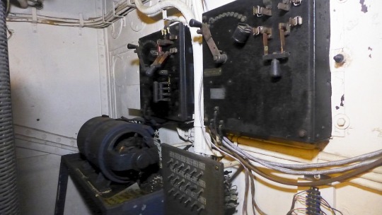
The round device at low, left is a motor generator set in Interior Communications compartment. Above it are two very old starter boards. The left one controls that m-g set. The right one controls a set that is out of frame. That one is dated 1918 and provided power to the newly installed Ford range keeper that generated firing solutions for the 14" guns.
Information from Tom Scott, a Volunteer at the Battleship Texas Foundation:
"AC power was certainly around by 1910 and was rapidly gaining traction throughout the country as the primary way of providing electric power, meaning the basic knowledge and technology for its use was available. So, the decision to use 120 volts D.C. on the ship wasn't based upon lack of ability. I am not aware of any historic documentation that discusses the Navy's decision for D.C., but what we can talk about are some of its advantages that contributed to its use and what was done to overcome its disadvantages.
AC current offers a couple of major advantages over DC, it's more efficient and its voltage can be easily changed using transformers. Fundamental to the nature of electricity is the higher the circuit voltage that serves a load, the lower the amperage required to run it, and vice versa. This made the use of 120 volts problematic because it required very large amperage circuits to power big loads like the 150 hp steering motor and the large number of motors sized 10hp and higher. My feeling is that it was selected due to the inability use transformers on a D.C. circuit to change voltage and the predominance of 120 volt loads on the ship that included hundreds of light fixtures and portable plug-in devices. It was simply easier to increase capacity and wire sizes to accommodate the higher amperage loads created by lower voltage than to increase the voltage design of hundreds, if not thousands, of small devices to match a higher system voltage.
Another issue that certainly affected the decision was the ability to reverse motors and control their speed. That was difficult to do with AC motors and was generally accomplished in the early 20th century with multiple winding motors that were complicated and very expensive. That's where DC offers two very significant advantages that permitted the use of simple and compact motor designs. It is easy to reverse any D.C. motor by reversing polarity, done by reversing its two power wires. Speed can be controlled by increasing or decreasing resistance in its its power circuit. That is impossible to do with A.C. motors. Small motor speed can easily be changed using a rheostat, or variable resister that uses a wiper on a resistive winding. Large motor speed control was accomplished using several large resistors that were switched in and out of the circuit with contactors. You could have almost smooth, almost continuous speed control if you had enough of them. Electric steering and its huge 150hp electric motor is the largest example on board that took full advantage of that method. Other motors, like those used to train turrets and elevate guns only ran at one speed, but had to be very accurately adjusted to the correct settings using resistor banks.
Regardless of the predominance of D.C. devices on board, the need for AC current and different voltages was present in the ship's earliest years of service and it greatly increased over time. The solution was to use motor generator sets, called m-g sets, on board where a 120 vdc motor would run an ac alternator to provide ac current and the voltage needed by a single device. In the Interior Communications compartment, there are several small ones dating back to 1916-18. There are also two very large ones synchronized together to power a large number of "selsyn (self synchronizing)" circuits that among other things, were used to provide range and bearing information from fire control towers to main battery plot and firing solutions to the guns. Others were installed in the dynamo rooms that powered the 40mm gun mounts and also provided a different dc voltage to the ship's degaussing system. However, most m-g sets were scattered throughout the ship, close to the devices that needed them. That way, they were able to avoid long wiring runs to reach the loads or changes to the overall system. They could tap into the existing 120 volt ship's system to get their power. That wasn't an easy task since it required careful engineering and design to prevent overloads or imbalances, but it was do-able.
One of the larger issues was to provide the additional power as large, new ac powered devices were added that included more radio and radar equipment, and 1.1" then 40mm anti aircraft weapons. To accommodate that, system capacity was increased 33% by replacing the four original 300kw 120v.d.c. turbo generators with four 400kw Westinghouse units. They also picked up significant capacity by replacing the big electric ovens and ranges in the crew galley with oil fired units.
So, there were significant compromises and shortcomings that were inherent to the 120 volt D.C. system, but it answered a number of almost unsolvable problems in 1910-11 when the ship was designed.
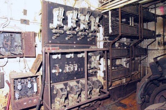
The resistor bank and contactors that controlled speed and direction for the 150hp electric steering motor.
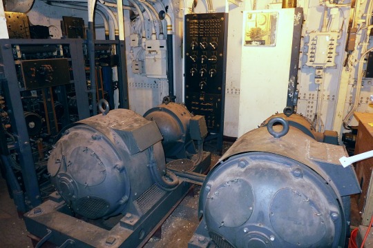
Here are the two largest motor-generator sets on the ship. They are located in Interior Communications and provided power to the gunnery systems that provided all of the range and bearing information from the fire control towers, and firing solutions to the gun turrets.
Hidden in very tight compartments beneath the turrets are the electrical platforms that contained all of the electrical panels and equipment that ran the turrets. The black boxes on the right side are resistor banks that controlled motor speed on the shell rammers.
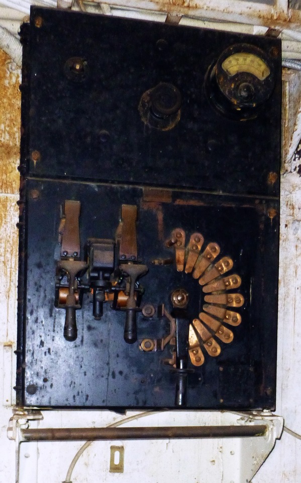
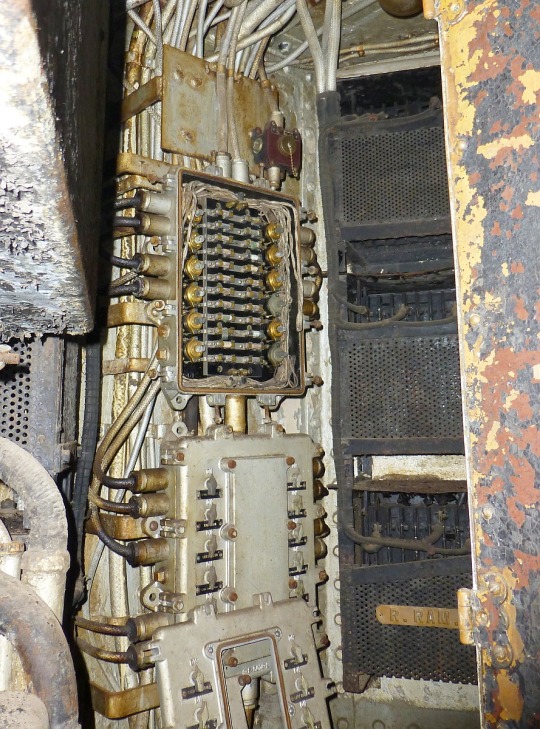
Here is one of the original 1912 controllers used on the 120 volt d.c. air compressors used to supply air charges that fired the torpedoes. The compressors were repurposed in 1925, when the torpedo tubes were removed, to serve the gas ejector systems on the 14" and 5" guns, but the old controllers remained. They were crude and simple, but they did the job well and were easily serviced.
Posted on the Battleship Texas Foundation Group Facebook page: link
21 notes
·
View notes
Text
how does shadow control his boots.
he certainly does not have additional joints attached to his feet (no extra fingers on feet) to press the buttons and turn the handles inside his boots. maybe it is the case, and that is why he never puts his boots off, but that sounds horrible. besides, if that was the case, if shadow was unconscious but someone was falling with with him, they can put their hands into his boots and turn the knobs to fly.
if he flicking foot is enough to activate his boots then he won't be able to tiptoe at all. if a specific sequence of toes' movements control his boots then that's gonna cause so much trouble when his toes itch.
if it's controlled with audio, then it makes shadow capable of making sound out of hearing range. in main universe that will essentially disable rouge to so many extents so this cannot be case.
if it's controlled with telepathic waves then shadow hovering will constantly drive silver crazy, or at least mildly annoyed. none of that happened; in fact it's the other way, as in silver annoying shadow by existence for a while.
maybe his red stripes on ends of his arms and legs are covers for underlying conductors, and when peeled, it would expose conductive terminals capable of supplying power and signals. it can be done with 2 terminals (vcc/gnd) but that would require so much caring to control the output. to delegate the details in control, it should have at least 2 more terminals (tx/rx). the gold rings are actually handles for rotational variable resistor. putting them off after rotating is purely for dramatic effects. he gotta act cool after all.
maybe the terminal layouts make him easily compatible with eggman robots. no need to fight them hard; just find their debug terminal, put his boots off, and step into it. boom, the eggman robot is now essentially an exosuit for shadow.
17 notes
·
View notes
Text

The Flowserve Apex 7000 Electro-Pneumatic Positioner (0-160 PSI) is a high-performance device designed for precise valve control in industrial automation. It converts electrical signals into accurate pneumatic output, ensuring smooth and efficient valve operation. Built for reliability and durability, it withstands harsh environments and delivers fast, responsive performance. Ideal for industries like oil & gas, water treatment, and chemical processing, this positioner enhances system efficiency. With easy installation, low maintenance, and superior control accuracy, the Apex 7000 is a trusted choice for automation professionals. Get the Flowserve Apex 7000 at Auto2mation for top-quality flow control solutions.
#industrial automation#industrial equipment#industrial spare parts#industrial#automation#industrial and marine automation#industrial parts supplier#industrial innovation#automation solutions#Marine Automation#marine equipment#marine spare parts#auto2mation#Automation#manufacturing#Flowserve Apex#Electro Pneumatic Positioner#Potentiometer#Variable Resistor
0 notes
Text
The Universal Serial Bus is often not universal...
So there is this problem you often run into when doing development. You come up with a solution. You research the solution, and find only tiny amounts of people talking about it, and/or they seem to say many different things and disagree. Most of the time, that is for 2 reasons 1: it is a very novel solution, so no one have tried it much, and everyone who have, has made very custom versions of it. 2: There are variables that makes it impossible to do it in one single way. I needed a rechargeable battery system to power my robot. These can get... VERY complicated, and pre-made solutions can quickly be expensive and you might end up with batteries catching fire, or destroying the batteries so they can never be used again. You need protections on them, but which kind depends on a bunch of things. I know electronics, but I am mainly a software guy, and I know when I do not know enough about electronics to do it myself. This being such a case. So, I came up with the idea to use powerbanks. One for each steppermotor, and one for the microcontroller(so the noise fromt he motors could not cause issues).If I use ones that can output enough amperage, they should just work and they are cheap. They are meant to be used by normal costumers, so have all the protection needed, and are quite idiot-proof(Which is a very handy thing when you are an idiot, like me) so should be easy to use. But I could not find much info about doing this... and I did not realize I was looking at reason 2. Basically, BECAUSE powerbanks are idiotproof, they do not want to discharge themselves unless there is a real device at the end of the USB cable. So if they cannot detect one, they turn off after about a second. How do they determine if there is a real device? Depends on the power bank.... No really, there is NO standard way to do it, as far as I can tell. And it does not depend on the power bank MODEL. I have 2 identical power banks, bought at the same time, and they do NOT behave the same. Which means that when I connected the powerbanks to supply my system, they (SOMETIMES) did not supply anything. Some check how much current is being drawn, which can be faked with a resistor wasting some power. 500mA was being quoted a lot, but that is more of a "That is probably enough to get it going". Others check for impedance(Basically, also resistance, but from frequency dependent sources). Those can be "faked" by having a coil or a device that acts like one to the faking resistor. I wanted a tiny 5 volt fan to cool the stepper motor drivers anyway, so I had one power bank also power that. That ensured that it actually stayed on (But if I used the other, (identical!) power bank it just turned off anyway). The other one could be connected up directly. If I used the powerbanks lower amperage socket. If I used the high amperage one, it just turned off. So now it works... I have 2 powerbanks for the motors, each with painters tape marking which powerbank and socket to use for what. Took me a week longer than I had hoped to figure all this out and do all the experiments. Sometimes, things that should be simple are just headaches.
7 notes
·
View notes
Text
Electronics Components and Uses:
Here is a list of common electronics components and their uses:
Resistor:
Use: Limits or controls the flow of electric current in a circuit.
Capacitor:
Use: Stores and releases electrical energy; used for filtering, timing, and coupling in circuits.
Inductor:
Use: Stores energy in a magnetic field when current flows through it; used in filters, transformers, and oscillators.
Diode:
Use: Allows current to flow in one direction only; used for rectification, signal demodulation, and protection.
Transistor:
Use: Amplifies and switches electronic signals; fundamental building block of electronic circuits.
Integrated Circuit (IC):
Use: Contains multiple electronic components (transistors, resistors, capacitors) on a single chip; used for various functions like amplification, processing, and control.
Resistor Network:
Use: A combination of resistors in a single package; used in applications where multiple resistors are needed.
Potentiometer:
Use: Variable resistor that can be adjusted to control voltage in a circuit; used for volume controls, dimmer switches, etc.
Varistor:
Use: Protects electronic circuits from excessive voltage by acting as a voltage-dependent resistor.
Light-Emitting Diode (LED):
Use: Emits light when current flows through it; used for indicator lights, displays, and lighting.
Photodiode:
Use: Converts light into an electric current; used in light sensors and communication systems.
Zener Diode:
Use: Acts as a voltage regulator by maintaining a constant voltage across its terminals.
Crystal Oscillator:
Use: Generates a stable and precise frequency; used in clocks, microcontrollers, and communication devices.
Transformer:
Use: Transfers electrical energy between two or more coils through electromagnetic induction; used for voltage regulation and power distribution.
Capacitive Touch Sensor:
Use: Detects touch or proximity by changes in capacitance; used in touchscreens and proximity sensing applications.
Voltage Regulator:
Use: Maintains a constant output voltage regardless of changes in input voltage or load; used for stable power supply.
Relay:
Use: Electromagnetic switch that controls the flow of current in a circuit; used for remote switching and automation.
Fuse:
Use: Protects electronic circuits by breaking the circuit when current exceeds a certain value; prevents damage from overcurrent.
Thermistor:
Use: Resistor whose resistance changes with temperature; used for temperature sensing and compensation.
Microcontroller/Microprocessor:
Use: Processes and controls electronic signals; the brain of many electronic devices and systems.
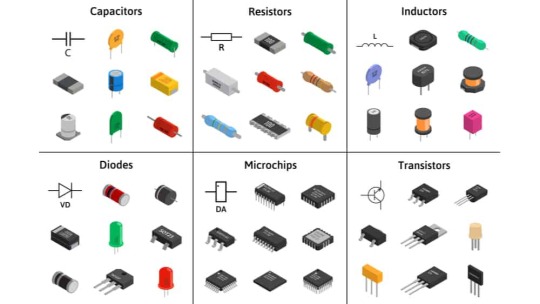
fig:google-electronics

fig:google-electronics
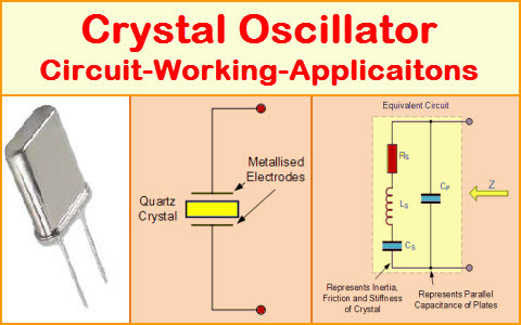
fig:Crystal-Oscillator
This list covers some of the basic electronic components, and there are many more specialized components used for specific applications within the field of electronics.
#electronic#electricity#electric vehicles#electric cars#engineering#semiconductors#wireless#cables#electronics#smartphone#hardware
4 notes
·
View notes
Text
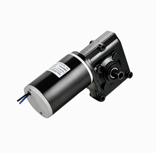
Exploring How the Speed of China DC Brushed Motor Can Be Effectively Controlled
The China DC Brushed Motor remains a widely used electromechanical component in various industries due to its cost-effectiveness, simplicity, and reliability. From small household appliances to industrial machines, these motors offer a straightforward solution for motion control. A critical aspect of their functionality lies in speed regulation. Whether for precision devices or variable-speed tools, controlling motor speed efficiently is essential. This article delves into the common methods used to manage the speed of a China DC Brushed Motor and how each technique impacts performance.
Voltage Control Method
One of the basic and direct ways to adjust the speed of a DC brushed motor is by varying the applied voltage. Since motor speed is nearly proportional to the supply voltage, increasing the voltage results in a higher rotational speed, while decreasing it slows the motor down. This method is simple and effective, especially in low-cost systems. However, it offers limited precision and may affect torque output and efficiency at lower voltages. Additionally, voltage drops under load can cause speed instability, making this approach less suitable for applications requiring consistent performance.
Pulse Width Modulation (PWM)
PWM is the commonly used method for precise speed control in a China DC Brushed Motor. Instead of reducing voltage directly, this technique turns the power on and off rapidly using electronic switches. By adjusting the duty cycle—the proportion of time the power is "on" during each cycle—PWM effectively controls the average voltage supplied to the motor. This allows for highly efficient speed modulation without significant power loss or heat generation. PWM also enables smoother acceleration and deceleration and is widely supported by microcontrollers and motor drivers, making it ideal for modern automation systems.
Closed-Loop Feedback Control
For applications where stable and accurate speed is critical, closed-loop systems are used. These systems integrate sensors, such as encoders or tachometers, that continuously monitor the motor’s speed and provide real-time feedback to a controller. The controller compares the actual speed to the desired value and adjusts the input (often via PWM) accordingly. This setup compensates for load changes or supply fluctuations and ensures consistent performance. Though more complex and costly, closed-loop control offers high precision and is frequently employed in robotics, CNC machines, and other demanding environments using China DC Brushed Motors.
Resistive Speed Control (Less Common Today)
In the past, series resistors were often used to drop voltage and thereby reduce motor speed. While still occasionally seen in low-tech or educational applications, this method is inefficient, as the resistor dissipates energy as heat. It also causes voltage instability under load and provides poor control resolution. As such, resistive methods are now largely obsolete compared to PWM and electronic controllers.
Digital Motor Controllers
Modern digital controllers bring together advanced techniques for controlling China DC Brushed Motors. These systems often combine PWM modulation, feedback loops, and interface options for programmable speed settings. Some even support communication protocols like CAN, UART, or I²C, allowing for integration into larger embedded systems. These controllers not only enhance speed control accuracy but also improve safety, protection, and diagnostics.
Conclusion
Controlling the speed of a China DC Brushed Motor involves a range of techniques, from simple voltage adjustments to advanced PWM and closed-loop systems. Each method has its strengths and trade-offs, with the choice depending on application requirements such as cost, precision, and energy efficiency. As technology evolves, smarter and more integrated control systems continue to expand the versatility of these reliable motors, ensuring their relevance across both traditional and modern industries.
Performance Highlights: Output Speed and Torque: The motor offers a versatile range of speed and torque options, allowing for customization to suit specific application requirements. The gearbox provides precise control over speed and torque output. Efficiency: With its brushed DC technology and precision gearbox, this motor delivers high efficiency, minimizing energy consumption and heat generation. Reliability: The 7712Z motor is designed for continuous operation with minimal wear and tear, ensuring a reliable performance over an extended lifespan.
0 notes