#Inline Testing Machine
Explore tagged Tumblr posts
Visit Tumblr Blog
Explore Tumblr blogs with no restrictions, modern design and the best experience.
Last Seen Tumblr Blogs


Fun Fact
The most popular pages on Tumblr are about Minecraft, GIFs, and David J. Peterson.
Text
High-Precision Inline Testing Machine | Marck Techno
The Inline Testing Machine by Marck Techno is a cutting-edge solution engineered to enhance quality assurance processes across various manufacturing sectors. Designed for seamless integration into production lines, this advanced system ensures real-time inspection, promoting consistent product quality and operational efficiency. The Inline Testing Machine offers continuous monitoring, enabling immediate detection of defects or inconsistencies during the manufacturing process. Capable of operating at impressive speeds, it maintains thorough inspection without compromising production throughput. Its adaptable design allows easy incorporation into existing production lines, minimizing downtime and facilitating swift deployment. Equipped with intuitive controls, operators can easily configure and monitor testing parameters, ensuring optimal performance. Ideal for industries such as automotive, electronics, pharmaceuticals, and consumer goods, the Inline Testing Machine excels in detecting defects, measuring dimensions, and verifying product integrity. Its precision and reliability make it an indispensable asset for manufacturers committed to delivering high-quality products. Marck Techno, based in Ahmedabad, Gujarat, has established a reputation for delivering innovative industrial solutions. Their Inline Testing Machine reflects a commitment to quality and technological advancement, providing manufacturers with a dependable tool to uphold stringent quality standards.
For More Details Clicks Here - https://marcktechno.com/product/inline-testing-machine/

0 notes
Text
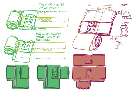
Please Reblog, I'd like to design a cheap braille typewriter (prototyping by 3d printing, final design will be machined) I stumbled upon linked YouTube short and a thought: "designing 6/8 button typewriter is within my technical capabilities"
youtube
I have many design questions I wish I could test out
My roadblock is I don't know anyone who's visually impaired, and casually seeking random place to peddle my soon-to-be-invention is not something I'm capable of
Many design questions:
Paper type: what is minimal quality/density of paper for dots to be readable. Can thermal receipt paper be used for notes?
Embossed vs punched out: is that significant for the typewriter to not break paper? It's important for "undo", but that's pretty far in my building a typewriter plan
Typewriter size: My initial idea was something like a portable cash register with receipt paper spool and little tray for it to glide along (I quickly realized it's a bad design because it can't fit more than 7 characters, or I can make infinite scroll of a single line with questionable ergonomics). Ultimately is related to page size, so what would be best for it? A4 standard paper? Is being portable important?
Keyboard layout: Perkins Brallier have all it's buttons inline forming long row. Wouldn't single-hand keyboard in similar layout as braille dots be more convenient? (straight grid or mimicking angle of computer keyboard letters)
Typing feedback: should typed letter be instantly accessible and not obstructed by typewriter? Maybe typing with one hand and instantly proof-reading with another hand?
Typewriter or printer?: alternatively, I can make a little annoying-noise-making servo-powered printer that will punch out text. Arduino or Raspberry PI based (I have experience with both) It would be USB powered most benevolent printer, because it don't require ink to work
Thanks for reading! [I'm not transcribing my design scribble, because it's absolute dogshit, but it helped me formula requirements. I will add transcription to actually thought of designs]
Alternatively, if I'm tweaking right now and if that thing would be needed it would already exist, I'll go back to trying to get hired by random megacorp and that's the last time you hear of me talking about it 💀
#braille#accessibility#inclusivity#blindness#blind#visually impaired#actually blind#low vision#visual impairment#Youtube
65 notes
·
View notes
Text
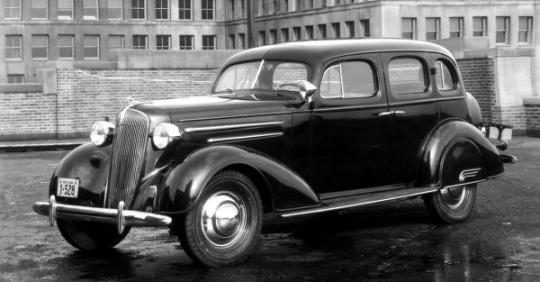
1936 Chevrolet
At General Motors in 1936, vehicle testing was remarkably sophisticated. See all the equipment and methods at work in this original Chevrolet film.
Like many of the Chevrolet films produced back in the day by Jam Handy of Detroit, this one, titled Wind, Weather, and Wheels, was designed to capture the interest of a general audience. So the script writers take a few minutes to get around to the actual subject—we call it the “first, the earth cooled” method of storytelling. But at around three minutes in (feel free to skip ahead) we get to the good stuff: a tour of the General Motors Proving Ground and a detailed look at the testing procedures for the ’36 Chevrolet.
For the mid-thirties, the test hardware is relatively sophisticated. At 4:40 we encounter a vehicle-sized pendulum for locating the center of gravity, and at 5:40 there’s an early chassis dynomometer with full instrumentation. Steering effort is checked with a wheel-mounted torqueometer, while a fifth wheel validates fuel consumption. And at around 9:30, a vacuum pump and smoke machine are used to test the cabin seal. We enjoy seeing this old gear at work, and along the way, there are some excellent views of the Proving Ground in its early, more rustic form. The facility, still a busy place today, is modestly described here as “the greatest outdoor laboratory in the world.”
In 1936, Chevrolet was not the best-selling car in the USA. In fact, Ford beat Chevrolet in total volume in ’34 through ’37, no doubt due in part to the selling power of Ford’s 85 hp V8. But with 79 hp, Chevy’s overhead-valve inline six was at least in the game, and a redesigned six the following year matched the Ford V8 in rated output. At $495 to $655, Chevrolet undercut Ford in pricing by a few bucks in ’36, losing to Ford by a mere 12,000 units. Video follows.
youtube
40 notes
·
View notes
Text
Mortal Kombat 1 & "Girl Power"
Content warnings: Unsurprisingly all the new Mortal Kombat trailers include high definition depictions of extremely gorey violence and death. Like, gives developers PTSD extreme. I will link to the trailers, but not include them inline. I did include a more cartoony Mortal Kombat 2 fatality.
Mortal Kombat (MK) has a long history, ever since Mortal Kombat 2, of not great female outfits.

Ed Boon has had a long history justifying this with "girl power" and that its a game where women get to be kickass, and now there's been an announcement that Mortal Kombat is setting up for... yet another reboot of the narrative.
So let's investigate Ed's claims of girl power, now they're giving the world a soft reboot and have used it to do redesigns and depict the characters in their ideal situations.
The new game Announcement Trailer that the characters now have a "choice" to live in quiet, serene lives they have - until we get a montage of Shang Stun just murdering them. Notably some of them get to make token effort to fight back, but it's not until the Gameplay Trailer we see them actually bust any worthwhile moves.
Kitana
In the initial trailer, Princess Kitana gets shown being carried in luxurious wagon before the crowds, accompanied by the oddly threatening Mileena. So... doesn't seem she's getting the same level of deep fulfilment the boys are.
The next time we see her - she's just like... kneeling in front of Shang Tsun and waiting to get her eyeballs gouged out with his thumbs.
In the second trailer, completely unconnected to the noble quest the boys are preparing for - she's having a battle with Mileena that seems fuelled by jealousy and paranoia.
We don't get to see any of her fatalities in the fatality montages - and while we see the boys testing one another, and building an alliance against their oppressor - we just see the girls squabbling.
Would this be an awkward time to bring up that Princess Kitana used to be 10,000 years old and expert at dealing with the machinations of the courts - unlike Fire God Liu Kang, she's been nerfed.

Mileena
Milenna gets shown riding with Kitana... and implied to be her rival, but is apparently now the actual Empress. then the next time we see her it's in a half-second clip of her getting her neck snapped effortlessly.
In the second trailer she trades blows with Kitana for a while, tagging in Goro to do some big hits and then later she's in a fight with one of the boys... the hits are done by another one of the boys she tags in.
We don't get to see any of her fatalities, which is pretty disappointing given that hers have often been particularly creative with the horror angle.


Sonya Blade
Sonya doesn't appear at all... and in the second trailer she rushes in during a fight to do like a weird, flip where she suplexes someone with her legs - then runs out again. Sort of a tag team feature that she seems to do just once.
She doesn't get a line, she doesn't get to show off a move set, she doesn't make a critical move and doesn't get a fatality. Sonya Blade, the original
Fuck you Ed, stop trying to justify your own jerk off material as "girl power" retroactively and pretending that you don't think women deserve to be badass. And give the people what they want to see:

That and like female characters who are as badass and badass looking as the boys - and shown to be as driven and interesting.
Ed, make Sheeva the main character of the promotions, you coward.

-wincenworks
#mortal kombat#mortal kombat 1#commentary#costume design#double standards#mileena#kitanan#sonya blade#video games#Bikini Armor Battle Damage#BikiniArmorBattleDamage#BABD
231 notes
·
View notes
Text


The collab and car that it never be. Top: BMW M1. Bottom: BMW M1 Procar/Grp.4
When M was just starting to expand, BMW had instructed them that they wanted to go racing and the boss of M division, Jochen Neerpasch, told BMW that in order for that to happen, BMW would have to build a mid-engined car to compete on the world stage and Grp.5 was their aim. However to compete in Grp.4 and 5 category, BMW had to build 400-500 cars of such caliber but BMW and M division had no idea on the know-hows. However, someone in Italy does and had already perfected the "mid-engine for the roads" concept and that's Lamborghini.
BMW then tasked Lamborghini in designing the car's design and work on the engine whereas BMW would work with the engineering and building of the car. Except... Lamborgini by the 1970s was in total financial shambles thus they couldn't complete their end of the deal thus on BMW's end, they had no engine and worse still, no chassis. Desperate, they got whatever they could from Lamborghini and paid any Lamborghini workers that left Lamborghini to complete the design of the chassis at least which, they did. Now with a chassis but lack of the V12 that was planned to be in the car since Lamborghini has pulled out of the deal, BMW was stuck but not for long.
To complement the car, M division started to design its own engine right out the gate and made a 3.5L inline-6 codenamed the M88 mated to a 5spd manual. Chassis work and body would all be worked on in Italy before being sent to Germany to be completed for the mechanical fittings and final testing. BMW would eventually build 453 of them with 399 being the normal homologated road-going version and the rest being race-prepped variants.
The M1 would also see a few variants of them across its production life from 1978-1981. With the normal road-going version, it has the normal M88 engine making 270hp. To make up numbers to even qualify for Grp.4, Jochen started to persuade BMW to launch their own one-make series with the M1 to boost sales and with that, the M1 Procar Championship was born and with the series comes the M1 Procar which had the M88/1 engine which was a normal M88 with an uprated cam making 450hp. Series ran for 2 years before the actual numbers for homologation was reached and they actually did well in Grp.4 class. Finally, they made it to Grp.5 and with the Grp.5 machines, the engine was this time downrated to 3.1L with the addition of a turbo with the classification of the M88/3 being able to make 750-900hp.
That being said, only the Grp.4 cars were officially built by BMW as the Procar Championship also followed Grp.4 regulations while the Grp.5 machines were all customer modified. The Grp.4 machines raced in other privateer events after BMW pulled the plug on the Procar Championship to focus on building engines for F1 whilst the Grp.5 machines all never seen any races but lived as mere prototypes.
3 notes
·
View notes
Note
After a slight incident of mistaken identity with the humans—Sentinel was all too happy to switch active patrol for monitor duty. It was such a shame the humans mistook his plow alt mode for one of their sanitation machines.
…Jazz would simply have to enjoy the less pungent parts of this organic city on his own, well, once he saw Blurr off. The intelligence officer hoped he could scout out where that “disturbing yet functional” construct took the AllSpark. A shame the blue speedster’s function meant it was against protocol to introduce him to the Repair Crew. Both of them agreed to a race at some point in Earth alts.
The elite cyber ninja was cruising along some of the less congested streets when—he picked up a faint AllSpark energy surge. Wanting to investigate and make sure this one wasn’t a Decepticon trap, he followed the signal.
Run down building after run down building met his optics pretty soon. Jazz remained vigilant in keeping an eye out for any swooping Decepticons. The fact all four known ‘Cons on Earth could fly meant he’d have to be extra ready to face aerial superiority. He kept following the signal eventually switching to root mode to maneuver where his alt couldn’t…
“Mrrrow?”
Jazz perked up at the sound of an organic creature meekly called out. To be careful, he ran it through the local network and come up with an organic called a “domestic feline”. Otherwise, most commonly known as a cat. He knew better now that organics couldn’t shoot slime—at least the intelligent ones… The elite cyber ninja decided to address the cat rather than let it stay unappreciated. “Uh, hello?”
Chances were it was one of the intelligent organics so he would be polite. Or try to be.
.
.
.
Something much heavier than what those little organics were supposed to way slammed into his pede hard. He had roll with the hit in order to minimize the damage as paneling cracked.
*Roooooooaaaaaaaaar!*
Jazz was met with the sight of a distinctly cybertronian form, though the alt mode was far more inline with those cat creatures!
—————————————
Lurker did not have echolocation abilities.
What they did have was heightened senses overall and the ability to utilize the Omnitrix as Theremin for disorientating soundwaves! The apparently further trained cyber ninja couldn’t employ hologram tactics if he can hardly think. Lurker felt quite proud of themself when they avoided reusing the same test that they gave to Prowl. If anything, the larger playlist gave them oh-so-many options to push the Elite Guard!
Were they being a little petty in taking it harder on the majority organicphobic Autobots?
Hmm, not really. Elite usually meant the best of the best, but if these four couldn’t take it? This showcased how bad another war against the Decepticons would go for Cybertron.
‘Hey, can I switch you to my tail hold?’
‘Yes. Why?’
‘I wanna steal his nunchucks.’
All the while, the smilodon cassette applied increasing pressure onto the struggling to adapt cyber ninja. Jazz was going to need to change his strategy soon or the Omnitrix user might as well force him to try something new—
A ninja star nearly grazed their ear earning a deep foundation shaking growl from them.
Prowl hopped into view looking disapproving.
*************************
“Are you alright?” The repair crew cyber ninja questioned over the comms, keeping a close eye on the “big cat”. Prowl had been observing organic life nearby when the menacing growls caught his attention… Their test for Jazz was far more unforgiving than his own had been.
The white and blue cyber ninja cautiously crept over to him, a faint limp in one pede. “Is this a common occurrence among the non-intelligent organics or… a test?” Jazz questioned in a flurry of comms. “Are you even allowed to interfere?” He kept his optics still observing the hostile presence here though he sounded worried for his fellow cyber ninja.
Prowl was touched, truly.
“Tag Team Battle Initiated.”
The shapeshifter suddenly spoke before tossing the cassette player they were… carrying…
In a similar transforming fashion, a cassette carrier towered over the two of them wearing the same hour glass symbol. A green visor blocked its optics from view yet the distinct lack of green in the cassette’s eyes told things.
Prowl uttered an Earth swear, then readied his stars to square up to the new challenge.
—ROB’d Anon.
I have planned this for ages. Can’t use ninja bullshit if you can’t think straight.
Looks like Prowl and Jazz are gonna team up for this test. Also valid on Dart to make things harder with the Elite Guard.

#sonicasura#sonicasura answers#asks#anonymous#ben 10#ben 10 series#ben ten#ben ten series#oc#original character#maccadam#transformers#transformers series#transformers animated#tf#tf series#tfa
4 notes
·
View notes
Text
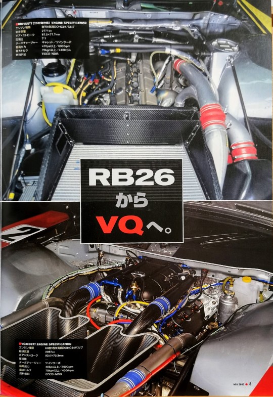
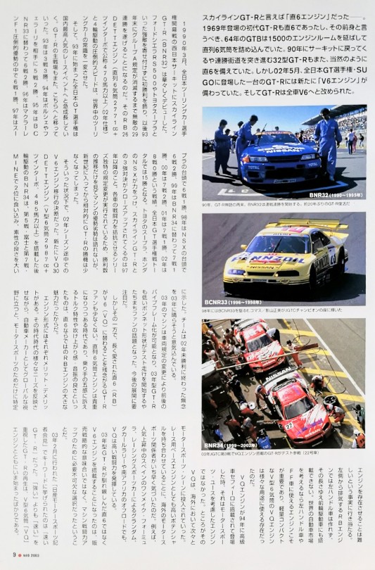
Speaking of the Skyline GT-R, it was a straight 6 engine. The first-generation GT-R, which debuted in 1969, was also a straight-six engine, and its predecessor, the 1964 GTB, had a 1500 with an extended engine room and a straight-six engine. The R32 GT-R, which returned to the circuit in 1990 and went on a winning streak, was naturally equipped with a straight-six engine. However, in May 2002, a GT-R that appeared in the All Japan GT Championship SUGO was equipped with a new "V6 engine." All GT-R models were changed to V6.
In March 1990, the Skyline GT-R (BNR32) made its spectacular debut at the West Japan Circuit at the opening round of the All Japan Touring Car Championship. He achieved his first victory by holding off strong opponents such as the Ford Sierra RS500 and Toyota Supra, and since then has won 30 races.
They would be on an unbeatable 20 race winning streak until the Group A regulations expire at the end of the year. The overwhelming speed of its RB26DETT engine (inline 6-cylinder 2771cc+ twin turbo with nominally over 470 horsepower/02 specification) and four-wheel drive completely changed the conventional wisdom of touring cars around the world.
The All Japan GT Championship, which started in 1993, rapidly grew to become the most popular racing event in Japan. The main battlefield for the GT-R has also shifted here. In 1993, it won 3 out of 3 races, in 1994 it won 2 out of 5 races against Porsche and Ferrari, in 1995 it was replaced with the BCNR33 and won 2 out of 6 races, and in 1996 it won 1 out of 6 races during the overwhelming dominance of McLaren F1. In 1997 1 win in 6 races with the rise of Supra, 2 wins in 7 races in 1998 with the rise of NSX, 1 win in 7 races in 1999 after replacing with BNR34. 2 wins in 7 races in 2000, 1 win in 7 races in 2001, and 0 wins in 8 races in 2002. This is a total of 15 wins in the All Japan GT Championship. It wasn't until 1999 that Toyota's Supra and Honda's NSX gained strength, and a close-up competition between them and the Skyline GT/R began. Due to changes in the regulations unique to the series that equalize the combat power of each car, it is impossible to say whether the machines are superior or inferior just by looking at the trends in the number of wins, but since the beginning of the new century, the GT-R has been relatively competitive. The chances of winning have diminished.
Under these circumstances, the decision was made to switch to a V6 engine midway through the 2002 season. The rear-wheel drive BNR34, equipped with the new VQ30DETT engine (V6 cylinder 2987cc+ twin turbo, over 485 horsepower), showed off its good origins by finishing in 2nd place at the 5th race at Fuji and at the 7th race at MINE. The team is disappointed that it ended 2002 without a win.
The team is determined to make amends for the lack of a win in 2002 in 2003.
The 2003 machine has changed before and after due to changes in vehicle regulations.
It became possible to use a vibrator frame, and the low hood shape of the 2003 GT-R became a hot topic among fans as soon as test runs began. We need to pay attention to future developments.
However, on the other hand, there are many GT-R fans who are disappointed that the long-loved straight-six (RB) will be replaced by the V6 (VQ). This was an era when in-line six-cylinder engines were becoming more valuable, and the RB engine's great appeal was its torque characteristics that appealed to the rider's five senses, as well as its good engine speed and vibration.
Each engine type has advantages and disadvantages. While reflecting the various needs of each era, from a global perspective as an automobile manufacturer, we created products specifically designed for motorsports.
We come to the fact that it is difficult to make an engine exhaust. An RB engine that exhausts from the left side cannot be used in left-hand drive cars, and because of its length, it cannot be installed in front-wheel drive cars either. When considering the global automobile market, it is important to have an engine that can be used in left-hand drive and front-wheel drive cars, and the lightweight and compact V-type 6-cylinder VQ engine can be used for a variety of purposes.
It was.
VQ engine became a luxury in 1999
When it was first introduced in the Cefiro car, it was not an engine designed for motorsports use. However, the VQ was introduced into the motorsports scene one after another overseas. Overseas motorsports officials were quick to realize that it had high potential as a base engine for racing. For example, Spain's one-make formula, which is becoming increasingly popular, Grand Am racing sports cars, the Dakar Rally, and off-road racing in South Africa.
VQ is demonstrating high combat power.
The decision to equip the 2003 model GT-R with a V6 engine instead of the familiar straight-six was not a sales strategy, but an essential choice to improve the machine's competitiveness. I'm saying that.
At the ``Nissan Motorsports Press Conference'' held in February 2003 the keyword mentioned was ``fast GT-R.'' The revitalization of the GT-R, which emphasizes ``fast'' rather than ``strong,'' has just begun with the V-6 VQ engine.
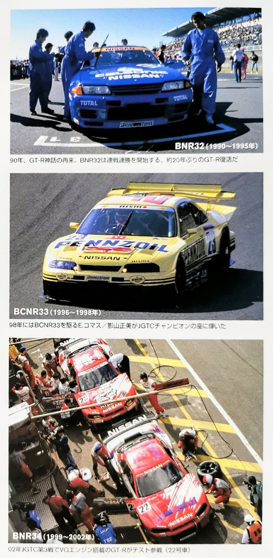
PIC CAPTIONS
BNR32 (1990~1995)
In 1990, the GT-R myth returns. BNR32 begins a winning streak. The GT-R is back for the first time in about 20 years.
BCNR33 (1996~1998)
In 1998, E. Comas/Masami Kageyama, riding BCNR33, won the JGTC championship.
BNR34(1999~2002)
GT-R equipped with VQ engine participates in test race at JGTC Round 3 in 2002 (car No. 22)
11 notes
·
View notes
Text
Mitscher IG JA-81 - "The Gunner's Perch"
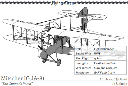
Role: Fighter/Bomber Served With: UWF First Flight: 1581 Strengths: Flexible Gun Post Weaknesses: Slow and Obsolete Inspiration: RAF Fe.2b (1914)
Description:
Johan Farmann’s final full design for MIG before his untimely death testing weapons mounts for the JA-83 fighter, the JA-81 essentially resembles an upscaled J-79.
Intended for use as a fighter-observer, the aircraft was forced to resort to an inline engine rather than Farmann’s preferred rotary due to stability issues, resulting in disappointing handling. However, the type was sturdy enough to stand up for itself in a fight and the gunner could gain an excellent field of fire by standing on their nacelle backwards and firing the pilot’s machine gun astern meaning that a series of bomber variants were produced as well.
Ritter, flush with success from the Sperling, also licensed the JA-81 but only built a few hundred before focusing on Scout production.
8 notes
·
View notes
Text
Bristol Beaufighter | Classic Warbirds
During the years preceding the Second World War (1939 ��� 1945) the Royal Air Force had set about modernising its aircraft. One of the roles it wanted a new aircraft for was that of a long-range fighter. As war in Europe looked ever more likely there was an urgency to get a new aircraft to fulfil this role into service. So Bristol set about working on a new design heavily based on its recent Beaufort torpedo bomber.
This new aircraft was to be powered by a pair of Bristol's Hercules engines and would use the Beaufort's landing gear, wings and tail based around a newly designed fuselage. Bristol submitted this new aircraft during October 1938 to the Air Ministry who ordered four prototypes. Nine months later on the 17th July 1939 the first Beaufighter prototype flew powered by Hercules I-SM engines with Captain Cyril Uwins at the controls. The second prototype was powered by the Hercules I-M with the 1,300-hp Hercules II powering the third and fourth prototypes. Just over a year after the first prototype flight the RAF received their first Mk Is on the 27th July 1940.
The Beaufighter Mk I had a top speed of 320 mph, thanks to its pair of 1,560-hp Hercules XI engines, a range of 1,500 miles and a service ceiling of 29,000 ft. Armament consisted of four 20mm cannons and six 0.303-in machine-guns, bomb load would consist of four 500lb bombs. This appeared in two sub variants the Mk IF night fighter which had Mk IV Airborne Interception radar installed and the Mk IC for use by Coastal Command. Reformed on the 15th June 1941 No. 143 Squadron at RAF Aldergrove would be the first to receive the Beaufighter Mk IC.
It would be the Fighter Interception Unit based at RAF Tangmere who would be one of the first squadrons to receive the Beaufighter Mk IF when they started to get theirs on the 12th August 1940 and they undertook their first operational sortie with the aircraft on the 4th September 1940. A further five squadrons, Nos. 25, 29, 219, 600 and 604 were equipped with the type by November 1940. It would be No. 219 Squadron who scored the aircraft's first aerial victory when a Dornier Do 17Z was shot down on the 25th October 1940. It was No. 604 Squadron who scored the Beaufighter's first radar assisted victory shooting down a Junkers Ju 88 on the 19th November 1940. A number of Mk IFs would be sent to operate as long-range fighters in the Western Desert and Mediterranean. Converted for use in the desert the need to improve range saw four 0.303-in machine-guns removed from the wings to be replaced by fuel tanks.

With Bristol's Hercules engines in demand elsewhere it was decided to look for an alternative powerplant in case of a Hercules shortage. This would lead to a Rolls-Royce Merlin powered Beaufighter Mk II. When two airframes were installed with a 1,075-hp Merlin X inline engine testing showed the centre of gravity in the Beaufighter moved which resulted in directional instability. This would require the tail end of the aircraft to be redesigned. The production version of the Mk II would be powered by the 1,300-hp Merlin XX, with the first example a Mk IIF flying on the 22nd March 1941, and had a slightly better top speed of 327 mph than the Mk I with the same range and armament. These would begin to enter service the following month.
The Beaufighter Mk IV and V were next. The Mk IV was intended to be powered by the Rolls-Royce Merlin XX but none were built. Two Mk Vs were and these saw a change in design with the addition of a Boulton Paul turret in the fuselage with four 0.303-in machine-guns. This would see a reduction in the mounted forward firing armament with the four 20mm cannons reduced to two and four 0.303-in machine-guns removed. These changes to the aircraft hampered its performance and no further Mk Vs were produced.
The Hercules powered Beaufighter Mk VI was next powered by either the 1,670-hp VI or the XVI. This gave the Mk VI a top speed of 330 mph, range of 1,500 miles, service ceiling of 29,000ft and armament of four 20mm cannons, six 0.303-in machine-guns with the ability to carry eight rocket projectiles. Fighter and Coastal Command started to receive their first Mk VI deliveries in early 1942. This was followed in May 1942 with tests which saw the Mk VI able to be armed with torpedoes. To begin with sixteen Mk VICs would be modified to carry torpedoes and these would enter service during June 1942 with No. 254 Squadron at RAF Dyce.

The next three intended Beaufighter variants were the Bristol Hercules 26 powered Mk VII, the Hercules XVII powered Mk VIII and Mk IX. These were to be built in Australia but none were produced. This meant the Beaufighter TF.Mk X was the next production variant, these would be nicknamed Torbeau. Powered by the 1,750-hp Hercules XVII engine it had a top speed of 323 mph, range of 1,500 miles with a service ceiling of 29,000 ft. Armament consisted of four 20mm cannons, six 0.303-in machine-guns, one Vickers 'K' gun, one torpedo and either 2,250lb bombs or eight 90lb rocket projectiles. The TF.Mk X would be used for anti-shipping operations and would be fitted with AI Mk VIII radar and this combination was to prove effective as shown in one 48 hour period when five German U-boats were found and sunk by Nos. 236 and 254 Squadrons TF.Mk Xs.
The Beaufighter Mk XI was the next production version, this was essentially a Mk X but without the ability to carry torpedoes. The Mk XI provided the basis for the Mk XII with the main change being an increased range but this would never enter production.
The Royal Australian Air Force would also take delivery of a small number of Beaufighters in 1941 and 1942. One of the squadrons to be equipped with the aircraft was No. 30 Squadron, Royal Australian Air Force and they would use the type in the Battle of the Bismarck Sea (2nd March 1943 - 4th March 1943). No. 30 Squadron, RAAF Beaufighters would be among a number of aircraft, including those of the United States Fifth Air Force, which during these three days would attack a Japanese convoy on its way to Lae, New Guinea which were ferrying troops and supplies. The following two years would see Beaufighters built under licence in Australia and these would become the Mk 21.

Based on the TF.Mk X the Mk 21, powered by the 1,600-hp Hercules 14, had a top speed of 320 mph, a range of 1,750 miles with a service ceiling of 29,000 ft. Armament consisted of four 20mm cannons and four 0.50-in machine-guns. The Mk 21 could carry a range of ordnance which comprised eight 5-in rocket projectiles, two 250lb bombs and two 500lb bombs and one Mk 13 torpedo. The first test flight of the new Beaufighter Mk 21 was made on the 26th May 1944 from Victoria, Australia. In total 365 examples would be built in Australia with the 6th November 1945 seeing the Royal Australian Air Force receiving their final Mk 21.
The final Beaufighter variant was the TT.Mk 10. These were previous Mks converted to serve as target tugs and would be the last of the type to serve with the Royal Air Force, its final sortie occurring on the 12th May 1960.
During its RAF career the Bristol Beaufighter would serve in a number of roles including night fighter, torpedo bomber and ground attack. During September 1942 Nos. 143, 236 and 254 Squadrons who operated the type formed the North Coates Strike Wing which would target North Sea shipping. It would be Nos. 236 and 254 Squadrons who undertook the first operation for this new force attacking a convoy on the 20th November 1942. By the time the war in Europe ended on the 8th May 1945 the North Coates Strike Wing would be credited with sinking over 150,000 tons of enemy shipping.

Perhaps one of the most audacious operations of the Second World War was carried out by a No. 236 Squadron Beaufighter Mk IC piloted by Flight Lieutenant A.K. Gatword with Sergeant G.Fern as his observer. This saw them perform a low-level daylight operation on the 12th June 1942 dropping a French Tricolore on the Arc de Triomphe in Paris, France.
The Bristol Beaufighter would serve with 52 squadrons and was also used as a target tug by the RAF until May 1960. The aircraft would be used by a number of other air forces including the United States Army Air Force and Royal Canadian Air Force and by the time production ended a total of 5,928 had been built.
Technical Details
Click on the aircraft image to view a larger version.
Top Speed Range Service Ceiling Armament
Beaufighter Mk I 320 mph 1,500 miles 29,000 ft four 20mm cannons
six 0.303-in machine-guns
four 500lb bombs
Beaufighter Mk II 327 mph 1,500 miles 29,000 ft four 20mm cannons
six 0.303-in machine-guns
four 500lb bombs
Beaufighter Mk III Was to be powered by the Bristol Hercules II, X or XI engine, none produced.
Beaufighter Mk IV Was to be powered by the Rolls-Royce Merlin XX engine, none produced.
Beaufighter Mk V Two examples built with a Boulton Paul turret with four 0.303-in machine-guns.
Beaufighter Mk VI 330 mph 1,500 miles 29,000 ft four 20mm cannons
six 0.303-in machine-guns
eight rocket projectiles
one torpedo
Beaufighter Mk VII Was to be powered by the Bristol Hercules 26 engine and built in Australia, none produced.
Beaufighter Mk VIII Was to be powered by the Bristol Hercules XVII engine and built in Australia, none produced.
Beaufighter Mk IX Was to be powered by the Bristol Hercules XVII engine and built in Australia, none produced.
Beaufighter TF.Mk X 323 mph 1,500 miles 29,000 ft four 20mm cannons
six 0.303-in machine-guns
one Vickers 'K' gun
one torpedo
and either two 250lb bombs or
eight 90lb rocket projectiles
Beaufighter Mk XI Like the Mk X but without the provison for a torpedo.
Beaufighter Mk XII Intended Mk XI version with a longer range, none produced.
Beaufighter Mk 21 320 mph 1,750 miles 29,000 ft four 20mm cannons
four 0.50-in machine-guns
one torpedo
two 250lb bombs
two 500lb bombs
eight 5-in rocket projectiles
Beaufighter TT.Mk 10 Converted to target tugs.
14 notes
·
View notes
Text
What Tools and IDEs Are Used in a Typical Python Programming Training Course?

Introduction
Python is one of the most popular programming languages in the world, known for its simplicity and readability. It's used in web development, data science, AI, and more. But writing Python code effectively requires more than just understanding syntax; you need the right tools and integrated development environments (IDEs). In any comprehensive Python online training with certification, understanding and using these tools is a crucial part of the learning journey.
According to the 2024 Stack Overflow Developer Survey, Python ranks as the most wanted language among developers. This shows a strong industry demand and growing interest from beginners. To keep up, python programming online training courses are integrating a variety of tools and IDEs that help learners practice, debug, and build projects more efficiently.
In this blog, we’ll explore the most commonly used tools and IDEs in a typical Python programming training course. You’ll learn what each tool does, why it matters, and how it helps in real-world scenarios.
Understanding the Python Development Environment
Before diving into individual tools, it's important to understand what makes up a Python development environment. In a typical Python online training with certification, the environment includes:
An IDE or code editor for writing Python code.
A Python interpreter to run the code.
Package managers like pip to install libraries.
Version control tools to track project changes.
Notebooks or dashboards for interactive development. These components help create a seamless workflow for coding, testing, and debugging.
Top IDEs Used in Python Online Training With Certification
PyCharm
Why it’s used in Python courses: PyCharm by JetBrains is one of the most feature-rich IDEs for Python. It supports python language online development with intelligent code completion, error highlighting, and integrated debugging tools.
Features:
Integrated debugging and testing
Smart code navigation
Refactoring tools
Version control support
Integrated terminal and Python console
Example in training: In Python online training with certification, students often use PyCharm to work on object-oriented programming projects or web development with Django.
Visual Studio Code (VS Code)
Why it’s popular: VS Code is lightweight, open-source, and customizable. With the Python extension installed, it becomes a powerful tool for any Python programmer.
Features:
IntelliSense for Python
Built-in Git support
Extensive extensions marketplace
Integrated terminal
Jupyter Notebook support
Example in training: VS Code is commonly used when introducing learners to data science libraries like Pandas and NumPy.
Jupyter Notebook
Why it’s essential for data science: Jupyter is more than an IDE; it's a web-based interactive computing platform. It allows you to mix code, output, visualizations, and markdown.
Features:
Inline visualization (great for Matplotlib, Seaborn)
Segment-based execution
Easy documentation with Markdown
Works seamlessly with Anaconda
Example in training: Used extensively in Python online training with certification for data analysis, machine learning, and statistics-based modules.
IDLE (Integrated Development and Learning Environment)
Why it’s beginner-friendly: IDLE is Python’s built-in IDE. While basic, it’s often introduced first to help learners focus on understanding syntax and logic without distractions.
Features:
Lightweight and easy to install
Simple REPL environment
Good for small scripts and exercises
Example in training: Used during the early phase of the course for learning variables, control flow, and functions.
Essential Tools for Python Programming
Python Interpreter
Every Python course requires a Python interpreter to execute the code. Python 3.x is the standard for most training programs today.
Key Use: Interprets and executes your code line-by-line, providing immediate output or error messages.
Anaconda Distribution
Why it’s useful: Anaconda is a bundle that includes Python, Jupyter, and hundreds of scientific libraries. It's widely used in data-heavy training modules.
Benefits:
Easy package management via Conda
Comes with Jupyter pre-installed
Ideal for machine learning and data analysis
Real-world tie-in: Many professionals use Anaconda in industry settings for AI and analytics work, making it highly relevant in Python online training with certification.
Version Control and Collaboration Tools
Git and GitHub
Why it's taught in courses: Version control is a must-have skill. Students are introduced to Git for local version tracking and GitHub for remote collaboration.
How it’s used:
Commit and push changes
Work in teams on group assignments
Review and merge pull requests
Example Project: Building a multi-file Python project with collaboration using Git branches.
Python Package Management Tools
pip (Python Package Installer)
Used in nearly every course, pip allows students to install packages from the Python Package Index (PyPI).
Command Example:
bash
pip install requests
virtualenv and venv
These tools are used to create isolated environments, avoiding package conflicts across projects.
Why it matters in training: It teaches learners how to manage dependencies correctly.
Code Linters and Formatters
Pylint and Flake8
These tools help identify syntax errors, poor coding practices, and PEP8 violations.
How it helps learners:
Immediate feedback on bad code
Encourages good coding habits
Prepares for real-world collaboration
Black
Black is an automatic code formatter that enforces a uniform style.
Why it’s taught: In professional development environments, consistent code style is crucial. Black makes that easy.
Jupyter Notebooks and Interactive Coding Tools
Google Colab
Why it’s included: Google Colab provides free cloud-based Jupyter notebooks with GPU support. It’s great for training AI and ML models.
Features:
No local setup required
Supports Python 3 and major libraries
Shareable and collaborative
Thonny
A beginner-friendly IDE ideal for introducing students to debugging and variable tracking visually.
Used for: Explaining loops, conditionals, and function scopes visually.
Real-World Applications in Training Projects
Web Development
Tools Used: PyCharm, Flask/Django, GitHub
Project Example: Build a blog website with CRUD features.
Data Analysis
Tools Used: Jupyter, Pandas, Matplotlib
Project Example: Analyze COVID-19 datasets and visualize trends.
Machine Learning
Tools Used: Google Colab, Scikit-learn, TensorFlow
Project Example: Build a linear regression model to predict housing prices.
Automation Scripts
Tools Used: VS Code, Selenium
Project Example: Automate login and data scraping from websites.
Key Takeaways
Python online training with certification includes tools that mirror real-world job roles.
IDEs like PyCharm and VS Code enhance learning through code suggestions, debugging, and integration.
Jupyter and Colab are essential for data-driven modules.
Git, pip, and virtual environments introduce real-world development workflows.
Code linters and formatters help build professional-level coding habits.
Conclusion
Whether you're aiming for data science, web development, or automation, understanding the tools and IDEs used in a python programming training course is crucial. These tools don't just make learning easier, they prepare you for real-world coding jobs.
Ready to sharpen your Python skills and build job-ready projects? Start learning with the right tools today!
0 notes
Text
Curved Batteries: The Future of Sleek Wearables 🌀🔋
Wearable electronics are quickly evolving, and so are the energy storage solutions that power them. As devices become thinner, more flexible, and designed for the human body, traditional battery shapes no longer fit the bill. That’s why curved batteries are becoming a key part of innovation. As a lithium battery manufacturer, we at Ufine Battery have spent years developing custom curved battery solutions tailored to wearable tech.
In this article, we’ll explore how curved batteries are made, why they matter, and where they’re headed.

🎯 Why Curved Batteries Are a Game-Changer
Traditional lithium-ion batteries are rigid and rectangular. That works well for phones and laptops, but not for wristbands, rings, or smart glasses. Curved batteries change the game by adapting to the product's shape, not the other way around.
✅ More Design Freedom
With curved battery packs, engineers can place energy cells into rounded surfaces, wrap them around corners, or fit them into non-linear spaces. This opens up 30% more design freedom, especially important for:
Smartwatches
Fitness trackers
Smart jewelry
Medical sensors
Hearing aids
Design no longer needs to compromise comfort for power.
✅ Better Ergonomics
Curved batteries enable low-profile, lightweight wearables that sit close to the skin and move with the user. Comfort is no longer optional—it's expected by consumers. Flexible cells make it possible.
✅ High Performance in Small Spaces
Our curved lithium batteries pack just as much energy density as traditional cells. In many cases, they outperform flat packs because of improved surface integration and thermal management.
🔬 How Curved Batteries Are Designed
At Ufine Battery, we’ve developed a step-by-step process for curved cell design. Every project begins with understanding the mechanical, electrical, and thermal needs of the end product.
1. Defining the Curve Radius
The first decision is the bend radius—how tightly the battery needs to curve. This affects material selection, cell architecture, and separator flexibility.
2. Material Selection
Unlike flat batteries, curved cells require flexible substrates. We use:
Ultra-thin aluminum and copper foils
Flexible polymer separators
Soft PTC (positive temperature coefficient) materials
Our team balances conductivity, safety, and form factor in every choice.
3. Stress Simulation
We run mechanical stress simulations to predict how the battery will behave after thousands of flex cycles. This helps prevent delamination, separator puncture, or capacity loss.
4. Prototyping and Testing
Before production, each curved battery design goes through physical testing:
Bend cycle stress tests
Drop tests
Charge-discharge analysis
Internal resistance tracking
Heat and humidity stress tests
We want to be sure it works not just in the lab but in real-world use.

🏭 From Lab to Factory: Scaling Production
Scaling up curved battery production is a challenge most manufacturers aren’t ready for. But at Ufine, we’ve invested in tooling, training, and QC systems to make it work.
💡 Custom Tooling
Our factory uses precision rolling and laminating machines customized for flexible substrates. We also developed jig systems that allow each pack to be molded into specific curvatures without damaging electrodes.
🧪 Inline Testing
Every unit is tested for capacity, leakage, resistance, and dimensional tolerance—before and after curvature is applied. This prevents failures in the field.
🚀 Fast Turnaround
Even with all this testing, we’re known for fast production cycles. Unlike large brands with long lead times, we offer short turnaround—even for small runs.
💬 Why Work with Ufine Battery?
We’re not the largest battery manufacturer—but we’re proud to be the most adaptable. Our strength lies in our custom curved cell capabilities and customer-first approach.
What Makes Ufine Different?
📐 Custom Curved Cell Design: We tailor batteries to your product—not the other way around.
🛠️ OEM & ODM Services: From idea to prototype to scale, we’ve got you covered.
🔋 Full Range of Chemistries: Li-ion, 18650, LiFePO4, ultra-thin, high-temp, cold-temp, high-rate
📦 Small MOQs: Even one piece is enough to start your project.
⚡ Fast Response & Support: We answer quickly and clearly.
🕐 Quick Shipping: Don’t wait months. Get your parts on time.
🛡️ 1-Year Warranty: We stand by our quality and back it up.
Our clients include startups, medical device companies, smart wear brands, and even R&D labs.
👀 Where Curved Batteries Are Being Used
1. Smartwatches and Fitness Bands
Curved batteries are the heart of nearly every modern wrist-wearable. The slight arc allows them to sit flush against the wrist while maintaining enough power for Bluetooth, display, and sensors.
2. Medical Devices
Skin-mounted patches, hearing aids, and diagnostic bands all benefit from curved, low-profile batteries. Safety and long cycle life are especially critical here.
3. Fashion-Tech
Designers are creating earrings, bracelets, and rings that include smart functionality. Curved batteries make this possible without bulking up the piece.
4. AR Glasses
As augmented reality wearables go mainstream, flexible batteries help fit power cells into the temple arms without adding weight or discomfort.
📈 What’s Next for Curved Battery Innovation?
At Ufine Battery, we’re constantly experimenting with:
Ultra-thin flexible cells that are thinner than a credit card
Bendable LiFePO₄ chemistry for higher safety in flexible formats
Hybrid curve-pouch cells with asymmetric shapes
Battery+antenna integrated modules for wearable IoT
We're also testing smart coatings that improve water resistance and self-healing polymers that extend battery life.
📩 Ready to Talk Curved Battery Projects?
If you’re a designer, engineer, or startup founder working on wearables, we’d love to help. Our team can review your specs, suggest battery formats, and ship samples fast.
💬 Drop us a line at Ufine Battery 📦 Get a quote—even for just one piece 🎨 Need custom shapes? We do that daily ⏱️ Tight schedule? We deliver fast
The future of wearables is curved—and we’re powering it.
0 notes
Text
How Should Be Your Metal Roll Forming Partner to Boost Your Business?
Choosing the right metal roll forming partner can be the difference between smooth growth and constant headaches. Here’s what you should look for to ensure your supplier becomes a true business booster — not a bottleneck.

1. Proven ExpertiseYour roll foming machine manufacturing company should have deep technical knowledge and years of experience in your industry. Whether it’s automotive, construction, or custom applications, they should understand the material properties, tolerances, and design challenges specific to your needs.
2. Customization Capabilities Every business has unique requirements. A strong roll forming partner offers design flexibility — helping you optimize profiles, materials, and finishes to meet your exact specifications, not just pushing standard products.
3. Advanced Technology & Equipment Modern, well-maintained equipment and up-to-date technology ensure precision, consistency, and faster production times. Ask if your roll forming company use CNC controls, inline punching, or laser cutting — these can significantly improve your product quality and lead times.
4. Scalability & Capacity As your business grows, your partner should be able to keep up. Check their production capacity, storage capabilities, and lead time commitments to ensure they can handle larger volumes when you need them.
5. Strong Quality Control Consistent product quality is non-negotiable. Look for ISO certifications, in-house testing, and documented quality processes. A partner who proactively manages quality saves you costly rework and protects your brand reputation.
6. Responsive Communication & Support Fast, clear communication can save time and avoid misunderstandings. You want a partner who is responsive, transparent, and willing to collaborate on challenges, whether it’s design tweaks or urgent orders.
7. Competitive Pricing with Long-Term Value Price matters, but it’s not everything. A partner who delivers reliable quality, fewer defects, and better efficiency can actually lower your total costs over time — even if they’re not the cheapest on paper.
8. Commitment to Continuous Improvement The best suppliers are always looking for ways to improve processes, reduce waste, and innovate. A partner with this mindset can bring new ideas to the table that help you stay competitive.
Final Thought
Your metal roll forming partner isn’t just a supplier — they’re an extension of your business. Choose a partner who brings expertise, innovation, and reliability, and you’ll position your business for stronger growth and success.
0 notes
Text
Servo Piston Fillers Market Set to Reach $570.4 Million by 2035
The Servo Piston Fillers market is projected to grow significantly, with industry revenue estimated to increase to $570.4 million by 2035, up from $271.0 million in 2024. This growth is expected to occur at an annual rate of 7.0% from 2024 to 2035. Servo Piston Fillers play a vital role in various industries, including food and beverage packaging, pharmaceutical packaging, cosmetic packaging, and chemical packaging. The report highlights key opportunities for growth and revenue expansion across product types, end-users, automation levels, filling ranges, and facility types.
Detailed Analysis - https://datastringconsulting.com/industry-analysis/servo-piston-fillers-market-research-report
Key Drivers of Market Growth
The demand for Servo Piston Fillers is driven by several factors, including the growing need for precision and consistency in filling operations, particularly in sectors such as food, pharmaceuticals, and cosmetics. Technological advancements in filling machinery and automation are also expected to contribute to market growth. Additionally, increasing demand for hygienic and contamination-free packaging solutions, particularly in the food and pharmaceutical industries, is a key trend driving the market forward.
Competitive Landscape and Industry Leadership
The Servo Piston Fillers market is characterized by fierce competition, with several leading players dominating the landscape. Key market participants include Accutek Packaging Equipment Companies, Cozzoli Machine Company, Pacific Packaging Machinery, Oden Machinery, Filling Equipment Company, APACKS Packaging, E-Pak Machinery, Inline Filling Systems, Universal Filling, Serac Group, Ronchi Mario, and FILAMATIC. These companies are focusing on technological innovations and product diversification to cater to the growing demand for precise and efficient filling solutions. Their strategic moves are expected to drive market expansion in key sectors and regions.
Opportunities and Trends Shaping the Market
The market is witnessing significant opportunities, particularly in the pharmaceutical sector, where there is a rising need for advanced filling technologies to ensure the integrity and safety of products. The ongoing technological revolution in packaging operations, including advancements in automation and smart technologies, is creating new avenues for growth. Additionally, untapped markets in developing nations offer significant revenue potential as manufacturers in these regions increasingly adopt advanced filling solutions.
Regional Insights and Evolving Supply Chains
North America and the Asia Pacific region are the leading markets for Servo Piston Fillers, driven by robust manufacturing bases and growing demand for high-quality packaging solutions. However, challenges such as high capital investment and a shortage of skilled labor are influencing the market dynamics. As the market evolves, supply chains for Servo Piston Fillers, from raw material procurement to assembly, testing, and distribution, are expected to expand. Industry players are expected to focus on emerging markets, such as Brazil, South Africa, and Indonesia, to diversify revenue streams and capture growth in these regions.
Conclusion and Future Outlook
The Servo Piston Fillers market is on a clear growth trajectory, with opportunities emerging from technological advancements, increasing demand for hygienic packaging, and untapped markets. As the market continues to expand, strategic partnerships, technological innovation, and regional diversification will be key to success in capturing a significant share of the market.
About DataString Consulting
DataString Consulting provides comprehensive market research and business intelligence solutions, offering customized research projects designed to meet specific strategic business objectives. With over 30 years of combined experience in market research and strategy advisory, DataString Consulting helps businesses navigate high-growth segments across various industries. The company’s expert team continuously monitors trends and provides actionable insights, supporting businesses in achieving their goals with precision and tailored solutions.
0 notes
Text
Cam Lock Couplings, Camlock Fitings, Industrial Quick Coupling
Manufacturer and Supplier of Cam Lock Couplings, Camlock Fitings, Quick Couplings, Industrial Coupling, SAE Flange Ball Valve, Mumbai, India.
Quick Release Coupling, Quick Release Couplings, Ball Valve, Ball Valves, Gemel Ball Valves, Industrial Ball Valves, Quick Coupling, Quick Couplings, Camlock Coupling, Camlock Couplings, Camlock Quick Coupling, Camlock Quick Couplings, Micro Hose, Micro Hose For High Pressure, Micro Hose For Pressure Fittings, Test Coupling, Test Couplings, Minipress Test Coupling, Minipress Test Couplings, Test Point Coupling, Test Point Couplings , Threaded Test Coupling, Threaded Test Couplings, Bulkhead Test Coupling, Bulkhead Test Couplings, Female Swivel Test Coupling, Female Swivel Test Couplings, Plug in Test Coupling, Plug in Test Couplings, Pressure Gauge Adaptors, Cartridge Valve, Cartridge Valves, Hydraulic Hoses, Hydraulics Hose, Hoses Crimped Hydraulic, Hydraulic Systems, Pneumatic Systems, Hydraulic Accessories, Hydraulic Couplings, Hydraulic Fitting, Hydraulic Fittings, SS304 Hydraulic Fittings, SS316 Hydraulic Fittings, CS Hydraulic Fittings, DIN 2353 Fittings, Pressure Gauge, Pressure Gauges, Industrial Valves, Coupling Valves, Hydraulic Components, Inline Valve, Inline Valves, Inline Flow Indicator, Inline Flow Indicators, Portable Hydraulic Crimping Machine, Portable Hydraulic Crimping Machines, Portable Hydraulic Instrument, Portable Hydraulic Instruments, Pressure Gauge Anti Shock Valve, Pressure Gauge Anti Shock Valves, Stainless Steel Hydraulic Components, High Pressure Check Valve, High Pressure Ball Valve, High Pressure Flow Control Valve, High Pressure Needle Valve, Non Return Valve, Gemels Italy Ball Valves, Holmbury Uk Couplings, Minipress Italy Couplings, Oleoweb Italy Valves, SS304 Csermeto Fittings, SS316 Csermeto Fittings, Flat Face Coupling, Quick Connect Disconnect Coupling, Screw Coupling 1000 Bar, Dust Cap, Test Point, Test Hose, Test Point Coupling, Test Point Hose, SAE Flange Ball Valve, Rotating Union, Hose Burst Check Valve, Compensated Load Control Valve, Compensated Flow Control Valve, Load Shuttle Ball Valve, End Stroke Valve, Single Acting Pilot Check Valve, Double Acting Pilot Check Valve, Double Cross Line Direct Acting Relief Valve, Single Cross Line Direct Acting Relief Valve, Sequence Valve, Single Counter Balance Valve, Dual Counter Balance Valve, Hand Pumps, Tube Clamp, Instrumentation Fittings, Lubrication Fittings, PP Pipe Clamp, Dowty Seal Copper Washer, Bonded Seal, Nut, Ferrule, asia, asian, india, indian, mumbai, maharashtra, industrial, industries, thane, navi mumbai, pune, nashik, aurangabad, ratnagiri, nagpur, ahmednagar, akola, amravati, chandrapur, dhule, jalgaon, raigad, sangli, satara, belgaum, kolhapur, belgaon.
0 notes
Text
Efficient Trapezoidal Screw Production Solutions: Techniques & Technologies
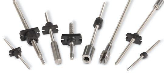
Trapezoidal screws, often used in linear motion systems and mechanical actuators, are critical components in a wide range of industries—from automotive to aerospace and industrial machinery. Known for their robust design and efficiency in converting rotary motion into linear motion, the demand for high-quality trapezoidal screws has significantly grown. As a result, manufacturers are constantly seeking optimized and scalable trapezoidal screw production solutions.
This article covers everything you need to know about producing trapezoidal screws, including materials, machining technologies, threading techniques, quality assurance, and automation trends in 2025.
1. What is a Trapezoidal Screw?
A trapezoidal screw is a type of lead screw with a trapezoid-shaped thread profile, typically conforming to standards like ISO or DIN. Unlike square threads, trapezoidal threads offer better load distribution and are easier to machine, making them ideal for high-load, low-speed applications.
Common Applications:
CNC machine beds
Linear actuators
Presses and lifting devices
Industrial automation systems
2. Choosing the Right Materials
Material selection is crucial for durability, precision, and resistance to wear. Common materials include:
Carbon Steel: Cost-effective and strong, often used with surface hardening.
Stainless Steel: Excellent corrosion resistance, preferred for medical and food-grade applications.
Bronze or Brass: Common for nuts paired with steel screws to reduce friction and galling.
Plastic or Polymer Composites: For low-load, high-speed applications, especially where lubrication is a concern.
Key Considerations:
Operating temperature
Load requirements
Corrosive environments
Maintenance cycles
3. Production Methods and Machining Solutions
a. Turning and Thread Cutting
Traditional lathes and modern CNC turning centers are used for cutting the trapezoidal thread profile.
Single-point threading on CNC lathes ensures precision but is time-intensive.
Thread rolling is a faster, deformation-based process ideal for high-volume production.
b. Thread Milling
Thread milling offers flexibility, especially for internal threads or difficult-to-machine materials. It reduces tool wear and produces cleaner finishes.
c. Grinding and Finishing
Post-threading, precision grinding improves surface quality and dimensional tolerance. Centerless and cylindrical grinding methods are popular for finishing the screw shaft.
4. Thread Standards and Tolerances
Global standards such as ISO 2904, DIN 103, and ANSI/ASME B1.5 define dimensions, tolerances, and profiles for trapezoidal screws. Precision is key, especially in applications where backlash or misalignment can impact performance.
Pitch accuracy and lead deviation must be tightly controlled.
Use of coordinate measuring machines (CMMs) and thread gauges ensures compliance.
5. Heat Treatment and Surface Coatings
To enhance durability and wear resistance, manufacturers often apply:
Case hardening or nitriding
Black oxide coating for mild corrosion resistance
Zinc or nickel plating
Teflon or PTFE coating for smooth motion
Each treatment is selected based on environmental conditions and expected wear cycles.
6. Quality Control and Inspection
Precision is everything. Key quality assurance practices include:
Microscopic inspection of threads
Surface roughness measurement
Load and torque testing
Dimensional accuracy checks with optical comparators
Modern facilities integrate inline sensors and AI-driven quality monitoring systems to flag defects in real-time.
7. Automation in Trapezoidal Screw Production
In 2025, smart manufacturing is transforming screw production. Here’s how:
a. CNC Automation
Automated lathes and thread milling machines minimize human error and increase consistency.
b. Robotic Handling
Collaborative robots (cobots) are used for part loading/unloading, inspection, and material movement.
c. MES Integration
Manufacturing Execution Systems (MES) streamline production planning, track progress, and optimize workflows.
d. Digital Twin Technology
Simulations of production lines and tool paths reduce setup time and improve first-pass yield.
8. Custom Screw Design Capabilities
Many industries require non-standard trapezoidal screws with customized:
Lengths
Thread profiles
Shaft features (flats, keyways, undercuts)
Nut assemblies (anti-backlash, split nuts)
Modern CAD/CAM software enables rapid prototyping and seamless CNC code generation, allowing quick design-to-production cycles.
9. Cost-Saving Strategies
To stay competitive, manufacturers implement the following strategies:
Batch production for economies of scale
Tool wear monitoring to avoid defects
Lean manufacturing principles to reduce waste
Local sourcing of raw materials to minimize delays and cost
10. Sustainability and Environmental Practices
Eco-conscious manufacturing is gaining ground. Companies are:
Using recyclable materials
Recycling cutting fluids and coolants
Installing energy-efficient CNC machines
Adopting green certifications like ISO 14001
Conclusion
The production of trapezoidal screws involves a blend of precision engineering, material science, and modern manufacturing technology. As industries demand more efficient, customizable, and high-performance lead screws, manufacturers must adopt advanced production methods and digital tools to stay ahead.
Whether you’re an established manufacturer or entering the lead screw industry, investing in optimized trapezoidal screw production solutions is key to meeting market expectations in 2025 and beyond.
0 notes
Text

#onthisday in 1940 the Fighter Interception Unit based at RAF Tangmere undertake their first operational sortie with the Beaufighter Mk IF.
Bristol Beaufighter | Classic Warbirds
During the years preceding the Second World War (1939 – 1945) the Royal Air Force had set about modernising its aircraft. One of the roles it wanted a new aircraft for was that of a long-range fighter. As war in Europe looked ever more likely there was an urgency to get a new aircraft to fulfil this role into service. So Bristol set about working on a new design heavily based on its recent Beaufort torpedo bomber.
This new aircraft was to be powered by a pair of Bristol's Hercules engines and would use the Beaufort's landing gear, wings and tail based around a newly designed fuselage. Bristol submitted this new aircraft during October 1938 to the Air Ministry who ordered four prototypes. Nine months later on the 17th July 1939 the first Beaufighter prototype flew powered by Hercules I-SM engines with Captain Cyril Uwins at the controls. The second prototype was powered by the Hercules I-M with the 1,300-hp Hercules II powering the third and fourth prototypes. Just over a year after the first prototype flight the RAF received their first Mk Is on the 27th July 1940.

The Beaufighter Mk I had a top speed of 320 mph, thanks to its pair of 1,560-hp Hercules XI engines, a range of 1,500 miles and a service ceiling of 29,000 ft. Armament consisted of four 20mm cannons and six 0.303-in machine-guns, bomb load would consist of four 500lb bombs. This appeared in two sub variants the Mk IF night fighter which had Mk IV Airborne Interception radar installed and the Mk IC for use by Coastal Command. Reformed on the 15th June 1941 No. 143 Squadron at RAF Aldergrove would be the first to receive the Beaufighter Mk IC.

It would be the Fighter Interception Unit based at RAF Tangmere who would be one of the first squadrons to receive the Beaufighter Mk IF when they started to get theirs on the 12th August 1940 and they undertook their first operational sortie with the aircraft on the 4th September 1940. A further five squadrons, Nos. 25, 29, 219, 600 and 604 were equipped with the type by November 1940. It would be No. 219 Squadron who scored the aircraft's first aerial victory when a Dornier Do 17Z was shot down on the 25th October 1940. It was No. 604 Squadron who scored the Beaufighter's first radar assisted victory shooting down a Junkers Ju 88 on the 19th November 1940. A number of Mk IFs would be sent to operate as long-range fighters in the Western Desert and Mediterranean. Converted for use in the desert the need to improve range saw four 0.303-in machine-guns removed from the wings to be replaced by fuel tanks.

With Bristol's Hercules engines in demand elsewhere it was decided to look for an alternative powerplant in case of a Hercules shortage. This would lead to a Rolls-Royce Merlin powered Beaufighter Mk II. When two airframes were installed with a 1,075-hp Merlin X inline engine testing showed the centre of gravity in the Beaufighter moved which resulted in directional instability. This would require the tail end of the aircraft to be redesigned. The production version of the Mk II would be powered by the 1,300-hp Merlin XX, with the first example a Mk IIF flying on the 22nd March 1941, and had a slightly better top speed of 327 mph than the Mk I with the same range and armament. These would begin to enter service the following month.
The Beaufighter Mk IV and V were next. The Mk IV was intended to be powered by the Rolls-Royce Merlin XX but none were built. Two Mk Vs were and these saw a change in design with the addition of a Boulton Paul turret in the fuselage with four 0.303-in machine-guns. This would see a reduction in the mounted forward firing armament with the four 20mm cannons reduced to two and four 0.303-in machine-guns removed. These changes to the aircraft hampered its performance and no further Mk Vs were produced.
The Hercules powered Beaufighter Mk VI was next powered by either the 1,670-hp VI or the XVI. This gave the Mk VI a top speed of 330 mph, range of 1,500 miles, service ceiling of 29,000ft and armament of four 20mm cannons, six 0.303-in machine-guns with the ability to carry eight rocket projectiles. Fighter and Coastal Command started to receive their first Mk VI deliveries in early 1942. This was followed in May 1942 with tests which saw the Mk VI able to be armed with torpedoes. To begin with sixteen Mk VICs would be modified to carry torpedoes and these would enter service during June 1942 with No. 254 Squadron at RAF Dyce.


The next three intended Beaufighter variants were the Bristol Hercules 26 powered Mk VII, the Hercules XVII powered Mk VIII and Mk IX. These were to be built in Australia but none were produced. This meant the Beaufighter TF.Mk X was the next production variant, these would be nicknamed Torbeau. Powered by the 1,750-hp Hercules XVII engine it had a top speed of 323 mph, range of 1,500 miles with a service ceiling of 29,000 ft. Armament consisted of four 20mm cannons, six 0.303-in machine-guns, one Vickers 'K' gun, one torpedo and either 2,250lb bombs or eight 90lb rocket projectiles. The TF.Mk X would be used for anti-shipping operations and would be fitted with AI Mk VIII radar and this combination was to prove effective as shown in one 48 hour period when five German U-boats were found and sunk by Nos. 236 and 254 Squadrons TF.Mk Xs.
The Beaufighter Mk XI was the next production version, this was essentially a Mk X but without the ability to carry torpedoes. The Mk XI provided the basis for the Mk XII with the main change being an increased range but this would never enter production.
The Royal Australian Air Force would also take delivery of a small number of Beaufighters in 1941 and 1942. One of the squadrons to be equipped with the aircraft was No. 30 Squadron, Royal Australian Air Force and they would use the type in the Battle of the Bismarck Sea (2nd March 1943 - 4th March 1943). No. 30 Squadron, RAAF Beaufighters would be among a number of aircraft, including those of the United States Fifth Air Force, which during these three days would attack a Japanese convoy on its way to Lae, New Guinea which were ferrying troops and supplies. The following two years would see Beaufighters built under licence in Australia and these would become the Mk 21.

Based on the TF.Mk X the Mk 21, powered by the 1,600-hp Hercules 14, had a top speed of 320 mph, a range of 1,750 miles with a service ceiling of 29,000 ft. Armament consisted of four 20mm cannons and four 0.50-in machine-guns. The Mk 21 could carry a range of ordnance which comprised eight 5-in rocket projectiles, two 250lb bombs and two 500lb bombs and one Mk 13 torpedo. The first test flight of the new Beaufighter Mk 21 was made on the 26th May 1944 from Victoria, Australia. In total 365 examples would be built in Australia with the 6th November 1945 seeing the Royal Australian Air Force receiving their final Mk 21.

The final Beaufighter variant was the TT.Mk 10. These were previous Mks converted to serve as target tugs and would be the last of the type to serve with the Royal Air Force, its final sortie occurring on the 12th May 1960.

During its RAF career the Bristol Beaufighter would serve in a number of roles including night fighter, torpedo bomber and ground attack. During September 1942 Nos. 143, 236 and 254 Squadrons who operated the type formed the North Coates Strike Wing which would target North Sea shipping. It would be Nos. 236 and 254 Squadrons who undertook the first operation for this new force attacking a convoy on the 20th November 1942. By the time the war in Europe ended on the 8th May 1945 the North Coates Strike Wing would be credited with sinking over 150,000 tons of enemy shipping.
Perhaps one of the most audacious operations of the Second World War was carried out by a No. 236 Squadron Beaufighter Mk IC piloted by Flight Lieutenant A.K. Gatword with Sergeant G.Fern as his observer. This saw them perform a low-level daylight operation on the 12th June 1942 dropping a French Tricolore on the Arc de Triomphe in Paris, France.
The Bristol Beaufighter would serve with 52 squadrons and was also used as a target tug by the RAF until May 1960. The aircraft would be used by a number of other air forces including the United States Army Air Force and Royal Canadian Air Force and by the time production ended a total of 5,928 had been built.
Technical Details
Click on the aircraft image to view a larger version.
Top Speed Range Service Ceiling Armament
Beaufighter Mk I 320 mph 1,500 miles 29,000 ft four 20mm cannons
six 0.303-in machine-guns
four 500lb bombs
Beaufighter Mk II 327 mph 1,500 miles 29,000 ft four 20mm cannons
six 0.303-in machine-guns
four 500lb bombs
Beaufighter Mk III Was to be powered by the Bristol Hercules II, X or XI engine, none produced.
Beaufighter Mk IV Was to be powered by the Rolls-Royce Merlin XX engine, none produced.
Beaufighter Mk V Two examples built with a Boulton Paul turret with four 0.303-in machine-guns.
Beaufighter Mk VI 330 mph 1,500 miles 29,000 ft four 20mm cannons
six 0.303-in machine-guns
eight rocket projectiles
one torpedo
Beaufighter Mk VII Was to be powered by the Bristol Hercules 26 engine and built in Australia, none produced.
Beaufighter Mk VIII Was to be powered by the Bristol Hercules XVII engine and built in Australia, none produced.
Beaufighter Mk IX Was to be powered by the Bristol Hercules XVII engine and built in Australia, none produced.
Beaufighter TF.Mk X 323 mph 1,500 miles 29,000 ft four 20mm cannons
six 0.303-in machine-guns
one Vickers 'K' gun
one torpedo
and either two 250lb bombs or
eight 90lb rocket projectiles
Beaufighter Mk XI Like the Mk X but without the provison for a torpedo.
Beaufighter Mk XII Intended Mk XI version with a longer range, none produced.
Beaufighter Mk 21 320 mph 1,750 miles 29,000 ft four 20mm cannons
four 0.50-in machine-guns
one torpedo
two 250lb bombs
two 500lb bombs
eight 5-in rocket projectiles
Beaufighter TT.Mk 10 Converted to target tugs.
9 notes
·
View notes