#Kalman filter method
Explore tagged Tumblr posts
Visit Tumblr Blog
Explore Tumblr blogs with no restrictions, modern design and the best experience.
Last Seen Tumblr Blogs


Fun Fact
The “We are the 99%” Tumblr blog became the slogan for the Occupy Wall Street movement.
Text
Elmalo, both directions are incredibly exciting and foundational to your vision. We have two compelling paths:
Sensor Fusion Layer Prototype:
Imagine an architecture where data flows seamlessly from ruggedized sensors—ranging from insect-inspired motion detectors to radiation-tolerant satellite telemetry—into a unified processing pipeline. This would involve designing edge computing nodes (using platforms like NVIDIA Jetson) that perform on-site preprocessing, robust data ingestion with tools like Apache Kafka, and sensor fusion algorithms (say, Kalman or Particle Filters) to harmonize disparate inputs. Establishing this blueprint lays the critical groundwork for real-time, high-fidelity environmental understanding essential for any subsequent AI processes.
Empathic AI Core Development:
Alternatively, we could plunge directly into the brain of Iron Spine by outlining the neural architecture. This entails building layers that connect multimodal inputs to emergent, empathic, predictive behavior. Picture combining transformers with recurrent networks to enable temporal awareness, alongside hybrid symbolic-AI methods for reasoned decision making. Adding an ethical overlay—transparency dashboards and fairness audit flows—would also be pivotal. Detailed model specifications, training regimes (leveraging diverse datasets across biological, mechanical, and environmental samples), and benchmark environments would form the core deliverables of this phase.
Given the ambitious breadth of your project, which path resonates more with your immediate priorities? Would you prefer to establish the tangible infrastructure of sensor fusion as a first step, or dive into the AI core mechanics that ultimately transform raw data into living, empathic intelligence? Let me know your thoughts so we can refine this next chapter of Iron Spine.
0 notes
Text
Revolutionizing Servo Control: How Spectrum Engineering Leverages High-Order Controller Auto-Tuning

In today’s fast-paced industries, precise servo control is vital for robotics, automation, and precision machinery. Tuning controllers to balance stability, speed, and robustness—while addressing friction, backlash, or sensor noise—is complex. Spectrum Engineering, with over 25 years of expertise in control system design consulting, transforms these challenges into opportunities, delivering control and dynamics innovation using the high-order controller auto-tuning method.
A Breakthrough in High-Order Tuning
Traditional tuning, often limited to PID designs, struggles with complex systems needing higher-order controllers for superior performance. However, research by Yaron Zimmerman and Per-Olof Gutman pioneers control and dynamics innovation by auto-tuning high-order controller implementation using unconstrained optimization within the Quantitative Feedback Theory (QFT) framework. By minimizing a cost function that balances performance and stability—without requiring a detailed plant model—this method ensures robust control across uncertainties like mechanical constraints. The Nelder-Mead Simplex Method optimizes parameters efficiently, reducing design time while achieving precision.
Spectrum Engineering’s Practical Solutions
Spectrum Engineering applies these principles to deliver tailored servo control solutions. Their automatic tuning algorithms optimize high-order controllers for embedded systems, addressing issues like saturation or dead zones. For instance, a client in industrial automation achieved faster response times and enhanced stability after their control system design consulting tuned their system to handle backlash. Beyond tuning, they implement Kalman filters to reduce noise, design algorithms for unique challenges, and support mechanical and electronic integration.
Why Choose Spectrum Engineering?
Through control system design consulting, patent collaboration, or team training, Spectrum Engineering offers flexible services. Why build an in-house control team when their expertise in control and dynamics innovation delivers high-performance systems? Their research-inspired approach ensures precision without complexity.
Leading the Future of Control Systems
As control systems grow intricate, Spectrum Engineering leads with advanced auto-tuning and practical know-how. Contact them for control system design consulting or explore their training to elevate your servo systems. With Spectrum Engineering, precision and performance are within reach.
#control and dynamics innovation#control system design consulting#Active magnetic bearing solutions#Controller implementation#Dynamics consulting#Dynamics performance optimization#Signal processing consulting#Custom control consulting services#Advanced control systems#Innovative control solutions#Motion control training#Control systems solution#Control loop tuning and optimization
0 notes
Text
Real-Time Object Tracking with the Kalman Filter: A Hands-On Tutorial
Introduction Real-Time Object Tracking with the Kalman Filter: A Hands-On Tutorial In this comprehensive tutorial, we will explore the world of real-time object tracking using the Kalman filter algorithm. The Kalman filter is a mathematical method for estimating the state of a system from noisy measurements. It is widely used in various fields, including robotics, computer vision, and…
0 notes
Text
AI Coding Tutorials
Artificial Intelligence (AI) is redefining how we interact with technology, changing industries, and influencing the future. Comprehending AI coding is an essential ability for prospective engineers, data scientists, and tech enthusiasts. The correct lessons can hasten your entry into the realm of artificial intelligence, regardless of your level of programming knowledge.
Essential Tools for AI Coding
Programming Languages
Frameworks and Libraries
Development Environments
Datasets
Top AI Coding Tutorials for Beginners
Coursera - Machine Learning by Stanford University
Google AI Crash Course
Kaggle’s Learn Platform
YouTube Channels
Advanced AI Coding Tutorials
Specialization in Deep Learning (Coursera)
discusses recurrent and convolutional neural networks.
practical TensorFlow and PyTorch projects.
Quick.ai
A method for AI coding that is useful.
Concentrate on developing applications as soon as possible.
Udacity's Robotics AI
Discover how to set up a self-driving car.
discusses sophisticated algorithms such as PID controllers and Kalman filters.
Tutorials for Hugging Faces
Learn NLP with pre-trained models and transformers.
Tutorials on AI coding will help you realize your full potential in one of the most fascinating areas of technology. You can become an expert in AI programming and create groundbreaking, impactful solutions with the correct tools, commitment, and practice. The field of artificial intelligence (AI) is ready for your innovative touch, whether your goals are to progress your career, solve practical issues, or advance technology. Get started now and turn your dreams of learning to code into a reality!
To know more, click here.
0 notes
Text
Unlocking the Future of Battery Systems with Advanced Modeling and Control Techniques
As the demand for battery-powered systems accelerates across industries—from smartphones to electric vehicles and grid storage—engineers face the challenge of designing efficient, reliable, and high-performance battery management systems (BMS). The "Battery Modeling and Algorithm Development" course offered by TechSource Asia provides an essential toolkit for professionals eager to excel in this rapidly evolving field.
Why This Course?
The two-day training focuses on leveraging MathWorks’ Simscape™ Battery™ and Simulink® platforms to model, simulate, and optimize battery packs with unparalleled precision. It combines theoretical foundations with hands-on application, making it ideal for engineers, researchers, and project managers involved in battery technologies.
Key Highlights
Participants will master the following:
Battery Pack Modeling: Construct high-fidelity models incorporating thermal and degradation effects using Simscape Battery.
State Estimation: Learn techniques for estimating the State-of-Charge (SoC) and State-of-Health (SoH) using methods like Coulomb Counting and the Extended Kalman Filter.
Control Algorithm Design: Develop supervisory control logic for charging/discharging and fault diagnostics, ensuring safety and efficiency.
Thermal Management: Integrate cooling systems into battery models for enhanced performance under varying conditions.
Fault Diagnostics: Detect voltage, temperature, and sensor anomalies to ensure reliable operation.
Benefits for Professionals
By the end of the course, participants will be able to design closed-loop battery management systems, perform cell characterization, and implement efficient algorithms for real-world applications. Complimentary post-training support further enhances learning outcomes.
Who Should Attend?
The course is tailored for:
Engineers and researchers developing battery-powered systems.
Professionals in automotive, renewable energy, and electronics sectors.
Academics and students looking to deepen their knowledge in battery technology.
A Gateway to Innovation
This course empowers participants to stay at the forefront of battery technology, equipping them with skills to innovate and optimize in diverse applications.
Explore the full details and enroll today at TechSource Asia’s website.
0 notes
Text
Understanding the Significance of Battery Voltage Measurement Accuracy in BMS
In the intricate world of Battery Management Systems (BMS), one paramount factor that often takes center stage is the accuracy of battery voltage measurement. Multiple lithium-ion battery manufacturing equipment suppliers usually ignore BMS accuracy. This seemingly technical parameter plays a pivotal role in determining the estimation error of a battery's State of Charge (SoC). But what exactly is SoC, and why is it essential?

Let's unravel the intricacies by considering lithium iron phosphate batteries as a prime example. These batteries exhibit a specific correlation between their Open Circuit Voltage (OCV) and SoC. To understand this, one needs to recognize the non-linear nature of the OCV-SoC curve. This curve depicts the relationship between the OCV of lithium iron phosphate batteries and their corresponding SoC.
As the battery undergoes discharging, internal chemical reactions lead to a gradual reduction in the OCV. Conversely, during the charging process, these reactions elevate the internal electrochemical potential energy of the battery, resulting in an OCV increase. The OCV-SoC curve takes on a distinctive shape, with steep voltage changes between SoC values of 0-20% and 80-100%. In contrast, the voltage shift is more gradual between SoC values of 20-80%.
This curve forms the basis for the Open Circuit Voltage method employed in practical applications to estimate SoC. It relies on measuring the battery's OCV. However, the accuracy of this estimation hinges on the precision of voltage measurements. A minuscule 1-millivolt (1mV) fluctuation in OCV can translate to a substantial 5% variation in SoC. This relationship is depicted in Figure 2, where you can observe how the change rate of each millivolt of voltage corresponds to different SoC values in the case of a typical lithium iron phosphate battery.
In practical terms, this signifies that if your voltage measurement is accurate to within 1mV, your SoC estimation will have an accuracy of approximately 5%. Furthermore, the change rate of each millivolt voltage corresponding to SoC differs for various charge states, thereby affecting SoC estimation accuracy across different charge states.
It's important to note that the discussion thus far pertains to the influence of voltage measurement accuracy solely when the OCV method is used for SoC estimation. In practice, other factors, such as discharge rate and operating temperature, also affect SoC estimation accuracy. To enhance accuracy, SoC estimation methods often employ a combination of approaches, including the ampere integral method, advanced techniques like Kalman filtering, or even cutting-edge deep learning AI algorithms.
As battery technology continues to evolve, precise voltage measurement remains integral to ensuring optimal SoC estimation, contributing to the efficiency and performance of various applications, from portable electronics to electric vehicles and renewable energy systems. Accurate voltage measurement enables intelligent BMS to optimize battery performance and enhance overall system reliability.
0 notes
Text
The Power of Sensor Fusion
March 29, 2024
by dorleco
with no comment
Autonomous Vehicle Technology
Edit
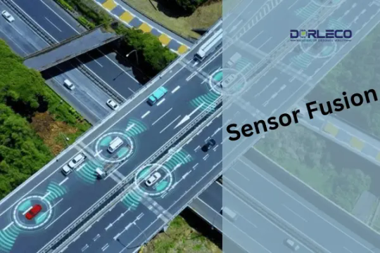
Introduction
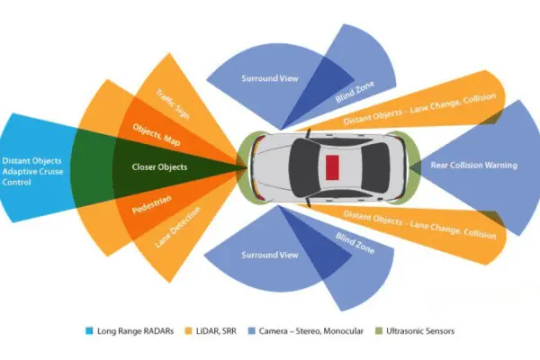
Multiple sensors with different specifications, operating circumstances, and ranges are needed for autonomous vehicles. Though they are susceptible to weather variations, cameras and vision-based sensors aid in the provision of data for recognizing specific objects on the road. Radar sensors are excellent in practically all weather conditions, but they cannot produce a precise three-dimensional representation of the environment. LiDAR sensors are costly, yet they provide a highly accurate map of the vehicle’s surroundings.
The Need for Integrating Multiple Sensors
Although each sensor has a distinct function, an autonomous car cannot use either one of them on its own. An autonomous car needs information from several sources to increase accuracy and gain a greater grasp of its surroundings if it is expected to make decisions that are comparable to—or, in some situations, even superior to—those made by a human brain.
Sensor fusion, therefore, becomes a crucial element.
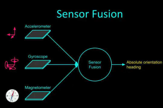
Sensor Fusion
In essence, sensor fusion refers to using all of the information gathered from the sensors positioned throughout the body of the car to inform judgments. This mostly aids in lowering the level of uncertainty that could otherwise be there when using individual sensors.
As a result, this combination aids in addressing each sensor’s shortcomings and creating a strong sensing system. In typical driving situations, sensor fusion typically increases system redundancy significantly. This indicates that different sensors are picking up on the same objects.
However, fusion helps guarantee that no items are missed when one or more sensors are inaccurate. For example, in perfect weather, a camera can record the surroundings of a moving car. That being said, the camera won’t give the system enough information when there is a lot of fog or rain. Here’s where LiDAR sensors and radar come in handy. In addition, a radar sensor might precisely detect the presence of a truck at the intersection where the vehicle is stopped at a red light.
It might not be able to produce data from a three-dimensional perspective, though. This is a necessity for LiDAR. Therefore, while in perfect circumstances having many sensors detect the same thing can appear redundant, in edge cases such as poor weather, sensor fusion is required.
Levels of Sensor Fusion
1. Low-Level Fusion, or Initial Fusion:
When using this type of fusion method, all of the data from all of the sensors is combined into one computer unit before it is processed. For instance, to determine the size and form of an item spotted, pixels from cameras and point clouds from LiDAR sensors are fused. Since this method transmits all of the data to the processing unit, it has a wide range of potential uses. As a result, different algorithms might make use of distinct data elements. The intricacy of processing is a disadvantage of transporting and managing such massive volumes of data. The cost of the hardware configuration will increase since high-quality processing units are necessary.
2. Fusion at the Mid-Level:
In mid-level fusion, the algorithm utilizes the data after the individual sensors have initially spotted the objects. This data is typically fused using a Kalman filter (described later in the course). The idea is to have, let’s say, a camera and a LiDAR sensor detect an obstacle individually and then fuse the results from both to get the best estimates of the vehicle’s position, class, and velocity. Although this is a simpler procedure to execute, if a sensor fails, there is a possibility that the fusion process will not succeed.
3. High-Level Fusion (Late Fusion):
This is comparable to the mid-level approach, with the exception that we fuse the outcomes after implementing detection and tracking algorithms for every single sensor. The issue is that the fusion as a whole could be impacted if there are tracking issues with one sensor.
Additionally, there are various kinds of sensor fusion. To maintain consistency, competitive sensor fusion involves having different types of sensors generate data on the same object. Through the employment of two sensors, complementary sensor-fusion will be able to create a larger picture than either sensor could on its own. Coordinated fusion will raise the data’s quality. For instance, to create a 3D representation of a 2D object, take two distinct viewpoints of it.
Variation in the approach of sensor fusion
1. Radar-LiDAR Fusion
Sensor fusion cannot be solved by a single method since different sensors have diverse functions. The mid-level sensor-fusion approach can be applied if a LiDAR and radar sensor need to be fused.
This entails combining the elements and concluding afterward.
This method can make use of a Kalman filter. This involves using a “predict-and-update” technique, in which the predictive model is updated to produce a better result in the following iteration depending on the previous prediction and the current measurement.
The following illustration illustrates this in an easier-to-comprehend manner.

The problem with the radar-LiDAR sensor is that LiDAR data is linear, whereas the data from the radar sensor is non-linear. Therefore, before being fused with the LiDAR data, the non-linear radar sensor data must be linearized, and the model is then updated appropriately.
An extended Kalman filter or an unscented Kalman filter can be used to linearize the radar data.
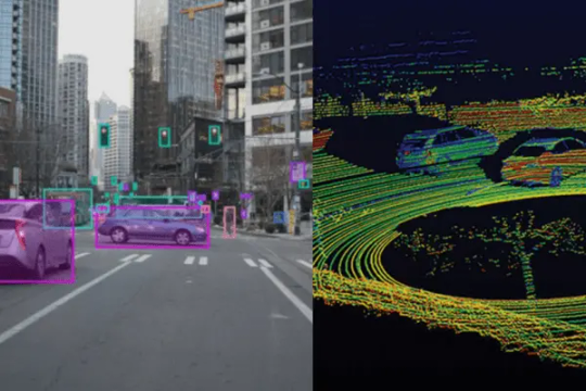
2. Fusion of Camera and LiDAR
Now, low-level fusion—which combines raw data—as well as high-level fusion—which combines objects and their positions—can be applied to systems that require the fusion of a camera and a LiDAR sensor. In both situations, the outcomes differ somewhat. The ROI (region of interest) matching technique and data overlap from both sensors make up the low-level fusion. The things in front of the vehicle are detected using the camera’s pictures, while the 3D point cloud data of the objects obtained from the LiDAR sensor is projected on a 2D plane.
Next, we superimpose these two maps to see if there are any common regions. The same object, identified by two separate sensors, is indicated by these similar regions. Data is first processed for high-level fusion, after which 2D camera data is transformed into 3D object detection. Following a comparison of this data with the LiDAR sensor’s 3D object detection data, the output (IOU matching) is determined by where the two sensors’ intersecting regions are.
Development of Autonomous Vehicle Features at Dorleco
Among the many things we do at Dorleco is develop sensor and actuator drivers. We can help you with full-stack software development or custom feature development.
Please send an email to [email protected] for more information about our services and how we can help you with your software control needs. You can also connect with us for all VCU-related products.
1 note
·
View note
Text
Mathematics for Robotics HW #10
Remarks: In Problem 2, we start playing with the Kalman filter. Start Problem 2 early enough that you can seek MATLAB help in time! 1. Estimating derivatives of functions numerically. In this problem, we introduce a method to estimate the Jacobian of a function numerically. (a) Compute the Jacobian of the following function f : R3 ! R analytically and evaluate it at the point x⇤ = [1 3 −…

View On WordPress
0 notes
Text
Blog | Kalman Filter 101: State Estimation | MATLAB Helper ®
Unlock the secrets of state estimation with MATLAB and the powerful Kalman Filter algorithm, used to navigate spacecraft and conquer the Moon!
#Kalman filter method#kalman filtering matlab code#kalman filter matlab tutorial#kalman filter simulink
0 notes
Text
#Kalman filter method#kalman filtering matlab code#kalman filter matlab tutorial#kalman filter simulink
0 notes
Video
tumblr
Method And Apparatus For Combining Data To Construct A Floor Plan: http://patentscope.wipo.int/search/en/WO2020023982
#Robot Mapping And Slam#Method for combining data to construct a floor plan#patents on Simultaneous Localization And Mapping (SLAM)#Extended Kalman Filter SLAM patent#EKF-based Simultaneous Localization And Mapping#color depth and Simultaneous Localization And Mapping#visual mapping and simultaneous localization#VIO Simultaneous Localization And Mapping#VI Simultaneous Localization And Mapping#Real-time Visual-Inertial Odometry Simultaneous Localization And Mapping (SLAM)#Patent on embedded SLAM
0 notes
Text
Elmalo, let's move forward with scoping a full pilot buildout—starting with the v1 Mars Habitat Monitor. This path offers a compelling, high-stakes testbed for the Iron Spine system and allows us to prototype under extreme, failure-intolerant conditions. Designing for Mars pushes the architecture to its limits, ensuring resilience, autonomy, and layered intelligence from the outset.
🚀 v1 Mars Habitat Monitor – Pilot Buildout
🔧 Environmental Design Requirements
Radiation-Hardened Components: Select radiation-tolerant MCU/FPGA and sensor components (e.g., RAD750 derivatives or Microsemi FPGAs).
Thermal Regulation: Passive and active methods (phase-change materials, aerogels, thin-film heaters).
Dust Protection: Hermetically sealed enclosures with electrostatic or vibrational dust mitigation (similar to the Mars 2020 rover’s approach).
Power Constraints: Solar panels + supercapacitors for charge buffering, with ultra-low power idle modes.
Communications Delay Tolerance: Incorporate DTN (Delay-Tolerant Networking) bundles for relayed Earth-Mars messaging.
🧠 Sensor Suite
Life Support Monitoring:
CO₂ / O₂ / CH₄ levels
Humidity / Temperature / Pressure
Structural Integrity:
Microfracture sensors (piezo-acoustic or fiber optic strain gauges)
Vibration analysis (accelerometers/IMUs)
Radiation Exposure:
Ionizing radiation detectors (Geiger-Müller tubes or RADFETs)
Environmental:
Dust density (LIDAR or IR scattering)
UV exposure, ambient EM fields
🧩 System Architecture
Sensor Synchronization:
Use local PTP clocks with oscillator drift correction from a central unit
Redundant clocks for fault detection
Data Fusion Layer:
Edge-level Kalman filters for each sensor type
Onboard anomaly detection with TensorRT-lite or ONNX models for pattern deviation
Edge Inference:
PyTorch Mobile or ONNX on an ARM-based SOM (e.g., NVIDIA Jetson Nano with radiation shielding)
Data Relay and Storage:
Store all telemetry in redundant onboard buffers
Use prepackaged DTN bundles and error-correcting transmission protocols to transmit during windowed comms
Digital Twin Integration:
Each monitor syncs with a simulated Mars habitat replica in Earth orbit or ground control
Dashboard via Prometheus/Grafana or a bespoke Unity/Unreal-powered 3D monitoring console
⚙️ Resilience & Power
Watchdog Timers: Auto-reset on failure, with a secondary power rail for minimal heartbeat signal
Power Monitoring: Real-time tracking of draw, supercapacitor status, and solar charge
Failover States: Downgraded functionality tier for power preservation and sensor core redundancy
Would you like a modular breakdown of the above, suitable for PCB design, mechanical housing, and software stack implementation? Or perhaps a visual mission profile that tracks expected operational phases, anomaly response, and maintenance cycles for the Mars system?
Let’s make this pilot the template for Iron Spine’s interplanetary leap.
0 notes
Text
SLAM Algorithm criteria and Robotics Help
The combination of guidance technology and automatic instruments may help decide the spot of applications. Aside from this, it includes a lot of pros to the aged. The idea is usually to support the elderly carry out their routine duties. Some of the great instances of the use of this technological innovation incorporate mechanized wheelchair navigation and autonomous automobiles. In this post, we are going to discover how SLAM sets of rules can be utilized in robotics for easy the navigation in a different environment. Read on for more information. The application of simultaneous mapping and localization is carried out to help ecological learning. The navigation is done through electromyography signals, even though this is done through the help of a mobile robot. In such a case, section of the method is reliant on consumer decisions. Put simply, the muscles Laptop or computer User interface, sometimes referred to as MCI, is responsible for mobile phone robot the navigation. Let's know look into some frequent strategies used in this technique. We shall also understand more about results of these techniques.

Techniques A SLAM algorithm based on a sequential Expanded Kalman Filtering (EKF) is a very common method. The functions from the method correspond to the lines and corners of the atmosphere. A universal metric chart is received from the design. Apart from, the electromyographic signs that control the actions in the robot may be tailored for the disabilities of the patient. For portable robot the navigation, MCI provides 5 directions: stop, Exit and start transform to the left and turn to the correct. For managing the mobile robot, a kinematic controller is carried out. Aside from, a powerful actions technique is utilized to prevent collision with the relocating brokers as well as the surroundings. The beauty of these methods is that they can be used in order to enjoy great results and prevent possible complications in the process. In order to get even better results, new research studies are being conducted to find out how these methods can be used. Outcomes The machine is tested by using volunteers. The tests can be executed in a lower vibrant surroundings that is certainly shut down. The volunteers might be given all around half an hour to get around the environment and have a much better idea of how to tap into the potential of MCI. According to previous experiments, the SLAM resulted in an environment that was consistently reconstructed. At the end of the experiment, a map was acquired and was stored inside the muscles computer graphical user interface. So, the process is quite efficient and can be used to enjoy great results. Conclusions Long scenario brief, the incorporation of slam with MCI continues to be very profitable to date. In addition to this, the interaction between the two is quite constant and profitable. The metric map made by the robot can aid autonomous the navigation down the road without the consumer interference. As being a motor-driven wheelchair, the mobile robot features a similar kinematic version. For that reason, it is a great benefit that may let wheelchair autonomous the navigation. To read more about Robotics quantum SLAM check out this resource.
1 note
·
View note
Text
Pairs Trading: Quantitative Methods and Analysis
Pairs Trading: Quantitative Methods and Analysis
Comprised of three information-packed parts, Pairs Trading presents an in-depth look at the various aspects of these strategies and provides quantitative tools to assist in their analysis. The first part of this comprehensive resource sets the context for the rest of the book by introducing preliminary material on some key topics, including time series, factor models, and Kalman filtering. After…

View On WordPress
0 notes
Text
Week 5: Design Process
Week 5, unlike the past few weeks does not have a SDL as it is solely focused on designing our timeline posters ready to be submitted as our formative.

After my initial sketches, I have started to compile those ideas and developed them into concept designs. I worked with a variety of elements as well as approaches, experimenting with various arrangements to find ones that I think would work well in the finals. This type arrangement was meant to be incorporated as a full composition design, but I had trouble working with this and wasn’t sure how to add in more text (timeline) without having the piece look too messy so I left this piece. This was meant to be my take on Tibor Kalman’s use of typefaces. I did quite like the text arrangement, the inconsistent and irregular sizes was an interesting concept to explore. I tried to re-create this method a few more times but ultimately decided that this method would be hard to utilise in a timeline poster that is filled with texts.

The next arrangement was slightly more simple, and has the minimalistic sense I was going for. In here, I focused more on arranging the texts in a way that is not overwhelming while slowly integrating colours into my works. Since Tibor Kalman works with bright colours, the arrangements was really important for me to highlight specific information. I have to be careful not to place colours randomly as it can very easily distract the audience and allow them to move away from the focal point.

In this composition, I was starting to feel a bit more comfortable with what I was making and how I was approaching these design elements. A lot of these techniques and arrangement are from my understanding of Kalman’s works and why he chooses to use certain text and colours. One of the most notable element in his work are his use of colours. He subtly adds colour onto texts and across pages, easily adding emphasis without the area of focus look to blaring. I tried to interpret this idea into my work here by really experimenting with colours, and using yellow (a naturally bright colour) to test out how and where I should utilise these colours.

Lastly, this composition was one of my favourite. I re-used many ideas and and techniques I have experimented with, with the previous designs by taking on a different approach. Again, Kalman’s works are highly pictorial, and I had this sudden inspiration to attempt to use a full picture. I was a bit hesitant at first because too much colour in a picture means that texts could easily get lost. But this issue was quickly solved when I properly utilised some filters. For this design, I incorporated Kalman’s typography and use of colour into my work, and tried to highlight the information using a guide (line). This worked out so much better than I had expected and I think the texts on face was a really fun take on Kalman’s use of text.
(05.04.2022)
1 note
·
View note
Text
Control of the Brushless DC Motor in Combine Mode
A brushless DC (BLDC) motor is considered to be a high performance gear motor due to its low maintenance cost, versatility, adequate torque and speed, and high reliability. Normally, a simple BLDC motor driver is composed of a permanent magnetic rotor and three stator coils. In each controlling step, two out of three coils are used to generate rotating magnetic field, while the floating coil induces a back electromotive force (emf) and feeds the generated current back to the controller as noise. In this work, combine mode scheme is proposed to control a BLDC motor in such a way that the excess current is accumulated via additional switching circuit for further utilization. Therefore, a BLDC motor can drive the load in concurrent with generating power. The proposed switching circuit has been designed and simulated on PSpice. The results show that up to 75% of input voltage can be charged to the storage capacitor.
This paper provides a technical review of position and speed sensorless methods for controlling Brushless Direct Current (BLDC) motor drives, including the background analysis using sensors, limitations and advances. The performance and reliability of BLDC motor drivers have been improved because the conventional control and sensing techniques have been improved through sensorless technology. Then, in this paper sensorless advances are reviewed and recent developments in this area are introduced with their inherent advantages and drawbacks, including the analysis of practical implementation issues and applications. The study includes a deep overview of state-of-the-art back-EMF sensing methods, which includes Terminal Voltage Sensing, Third Harmonic Voltage Integration, Terminal Current Sensing, Back-EMF Integration and PWM strategies. Also, the most relevant techniques based on estimation and models are briefly analysed, such as Sliding-mode Observer, Extended Kalman Filter, Model Reference Adaptive System, Adaptive observers (Full-order and Pseudoreduced-order) and Artificial Neural Networks.
For the past two decades several Asian countries such as Japan, which have been under pressure from high energy prices, have implemented variable speed PM motor drives for energy saving applications such as air conditioners and refrigerators [1]. On the other hand, the U.S.A. has kept on using cheap induction motor drives, which have around 10% lower efficiency than adjustable PM motor drives for energy saving applications. Therefore recently, the increase in energy prices spurs higher demands of variable speed PM motor drives. Also, recent rapid proliferation of motor drives into the automobile industry, based on hybrid drives, generates a serious demand for high efficient PM motor drives, and this was the beginning of interest in BLDC motors.
BLDC motors, also called Permanent Magnet DC Synchronous motors, are one of the motor types that have more rapidly gained popularity, mainly because of their better characteristics and performance [2]. These motors are used in a great amount of industrial sectors because their architecture is suitable for any safety critical applications.
The brushless DC motor is a synchronous electric motor that, from a modelling perspective, looks exactly like a DC motor, having a linear relationship between current and torque, voltage and rpm. It is an electronically controlled commutation system, instead of having a mechanical commutation, which is typical of brushed motors. Additionally, the electromagnets do not move, the permanent magnets rotate and the armature remains static. This gets around the problem of how to transfer current to a moving armature. In order to do this, the brush-system/commutator assembly is replaced by an intelligent electronic controller, which performs the same power distribution as a brushed DC motor [3]. BLDC motors have many advantages over brushed DC motors and induction motors, such as a better speed versus torque characteristics, high dynamic response, high efficiency and reliability, long operating life (no brush erosion), noiseless operation, higher speed ranges, and reduction of electromagnetic interference (EMI). In addition, the ratio of delivered torque to the size of the motor is higher, making it useful in applications where space and weight are critical factors, especially in aerospace applications.
The control of BLDC motors can be done in sensor or sensorless mode, but to reduce overall cost of actuating devices, sensorless control techniques are normally used. The advantage of sensorless BLDC motor control is that the sensing part can be omitted, and thus overall costs can be considerably reduced. The disadvantages of sensorless control are higher requirements for control algorithms and more complicated electronics [3]. All of the electrical motors that do not require an electrical connection (made with brushes) between stationary and rotating parts can be considered as brushless permanent magnet (PM) machines [4], which can be categorised based on the PMs mounting and the back-EMF shape. The PMs can be surface mounted on the rotor (SMPM) or installed inside of the rotor (IPM) [5], and the back-EMF shape can either be sinusoidal or trapezoidal. According to the back-EMF shape, PM AC synchronous motors (PMAC or PMSM) have sinusoidal back-EMF and high performance Brushless DC Motor have trapezoidal back-EMF. A PMAC motor is typically excited by a three-phase sinusoidal current, and a BLDC motor is usually powered by a set of currents having a quasi-square waveform [6,7].
Because of their high power density, reliability, efficiency, maintenance free nature and silent operation, permanent magnet (PM) motors have been widely used in a variety of applications in industrial automation, computers, aerospace, military (gun turrets drives for combat vehicles) [3], automotive (hybrid vehicles) [8] and household products. However, the PM BLDC motors are inherently electronically controlled and require rotor position information for proper commutation of currents in its stator windings. It is not desirable to use the position sensors for applications where reliability is of utmost importance because a sensor failure may cause instability in the control system. These limitations of using position sensors combined with the availability of powerful and economical microprocessors have spurred the development of sensorless control technology. Solving this problem effectively will open the way for full penetration of this motor drive into all low cost, high reliability, and large volume applications.
The remainder of the paper is arranged as follows. Section 2 describes the position and speed control fundamentals of BLDC motors using sensors. Next, Section 3 explains the control improvements applying sensorless techniques, describing the motor controller model and the most important techniques based on back-EMF sensing. Section 4 also briefly analyses the sensorless techniques using estimators and model-based schemes. In addition, Section 5 compares the feasibility of the control methods, and describes some relevant implementation issues, such as open-loop starting. Finally, Section 6 provides an overview for the applications of BLDC motor controllers, as well as conclusions are drawn in Section 7.
PM motor drives require a rotor position sensor to properly perform phase commutation and/or current control. For PMAC motors, a constant supply of position information is necessary; thus a position sensor with high resolution, such as a shaft encoder or a resolver, is typically used. For BLDC motors, only the knowledge of six phase-commutation instants per electrical cycle is needed; therefore, low-cost Hall-effect sensors are usually used. Also, electromagnetic variable reluctance (VR) sensors or accelerometers have been extensively applied to measure motor position and speed. The reality is that angular motion sensors based on magnetic field sensing principles stand out because of their many inherent advantages and sensing benefits.
2.1. Position and Speed Sensors
As explained before, some of the most frequently used devices in position and speed applications are Hall-effect sensors, variable reluctance sensors and accelerometers. Each of these types of devices is discussed further below.
2.1.1. Hall-effect sensors
These kinds of devices are based on Hall-effect theory, which states that if an electric current- carrying conductor is kept in a magnetic field, the magnetic field exerts a transverse force on the moving charge carriers that tends to push them to one side of the conductor. A build-up of charge at the sides of the conductors will balance this magnetic influence producing a measurable voltage between the two sides of the conductor. The presence of this measurable transverse voltage is called the Hall-effect because it was discovered by Edwin Hall in 1879.
Unlike a brushed DC motor, the commutation of a high performance BLDC Motor is controlled electronically. To rotate the BLDC motor the stator windings should be energized in a sequence. It is important to know the rotor position in order to understand which winding will be energized following the energizing sequence. Rotor position is sensed using Hall-effect sensors embedded into the stator [9].
Most BLDC motors have three Hall sensors inside the stator on the non-driving end of the motor. Whenever the rotor magnetic poles pass near the Hall sensors they give a high or low signal indicating the N or S pole is passing near the sensors. Based on the combination of these three Hall sensor signals, the exact sequence of commutation can be determined. Figure 1 shows a transverse section of a BLDC motor with a rotor that has alternate N and S permanent magnets. Hall sensors are embedded into the stationary part of the motor. Embedding the Hall sensors into the stator is a complex process because any misalignment in these Hall sensors with respect to the rotor magnets will generate an error in determination of the rotor position. To simplify the process of mounting the Hall sensors onto the stator some motors may have the Hall sensor magnets on the rotor, in addition to the main rotor magnets. Therefore, whenever the rotor rotates the Hall sensor magnets give the same effect as the main magnets. The Hall sensors are normally mounted on a printed circuit board and fixed to the enclosure cap on the non-driving end. This enables users to adjust the complete assembly of Hall sensors to align with the rotor magnets in order to achieve the best performance [10].
0 notes