#Load Options of 3D PLY
Explore tagged Tumblr posts
Visit Tumblr Blog
Explore Tumblr blogs with no restrictions, modern design and the best experience.
Last Seen Tumblr Blogs


Fun Fact
The Tumblr office adopted Tommy, an 11-year-old Pomeranian.
Text
BJJ Floating Mat System DIY Walkthrough
I’m going to share the process of building a floating mat system, from design to sourcing materials and build. I figured I try to take out as much guess work since I had no guidance and had to learn on my own. There were several pieces of the puzzle that came as some small surprises, but hopefully this helps the next person who decided to make the leap to a better mat system. I’m unsure of the process for other countries, but in my case I will detail the process for importing goods into New Zealand – it may differ in other places. I’ll include links to the factory for all the specific mats I ordered in the post.
Towards the end of Sept 2020, just after the Covid-19 lockdown ended in New Zealand, I had an opportunity to expand my BJJ club and sub-lease space in our existing gym we ran out of. I had an elaborate vision of a floating mat system underneath some juicy dollamur mats for use to train in.
I was introduced to the floating mat system years ago when I lived in Los Angeles on a visit to Kron Gracie’s academy in Culver City. I had worked down the street and wanted to congratulate him and have a look around. My friend Ollie Barre worked there and he showed me around, even Kron said hello and mentioned the spring loaded floating mat system to me.
It was about 1/2 a meter high with actual springs under the floor with plywood on top and tatame on top of the ply. It was amazing!
Image courtesy of Kron Gracie Academy Linkedin page
I knew that’s what I wanted but I didn’t have the budget for springs, so I explored other options. After a few searches I came across a couple videos:
How to build the ultimate spring subfloor for your Judo, Jujitsu and Wrestling mats
&
How to build a Bjj subfloor
Foam and ply – sweet I can do that! Let’s measure the space:
9.7m x 4m – pretty decent space!
After the measurement I needed to visualize the build. I knew I had to see it and make something for others to see the vision I had, so I modeled everything out in Maya and made a 3D render:
Concept render
I used real world units to keep everything to spec, that means the units I use in the 3D application are accurate to and equal to the units I would use on the actual build. The sub-floor would be the most difficult thing to explain to a builder, so I did a couple renders of what the underbelly would look like:
14 sheets of plywood with sub-floor foam block layout
Single sheet plywood foam block layout
I began compiling a list of materials I would need:
15 sheets of 2440mm x 1200mm x 12mm non-structural plywood
6 sheets of closed cell polyethylene foam
tons of liquid nail
timber for boxing in – unsure of spec at that time
5cm thick floor mats, tatame finish
21 wall mats @ 183cm x 122cm x 5cm
Living in New Zealand is awesome BUT sourcing some of these materials was going to be difficult and super expensive. I started calling around and emailing different foam companies and dollamur reps. I was getting quotes just for the dollamur mats of $5-6k NZD alone! I found a company that imports foam and was quoted $500/sheet of PE foam! I didn’t even bother looking at the wall mats – it would have cost me closer to 10K to get everything from NZ companies, so I decided to cut out the middle man and source materials myself.
Of course this lead me to Alibaba.com – the Chinese based website that gives people like myself access to factories where these things are typically made. After a few days of searching and multiple emails, I found a factory – Quindao Sanhong Plastic Co, LTD – that appeared to manufacture everything I needed – floor mats, wall mats and PE foam sheets.
It was my 1st time using Alibaba and to be honest I was SUPER dubious. I would be dealing with people outside of the country I lived in which carries a larger sense of the unknown.
I ended up chatting with a service person named Emily. She was incredibly helpful and thorough and made sure she understood what I required. I sent her an absurd amount of photos, videos, all of my renderings of what I had in mind, the measurements and other specs. She talked me into getting a more dense mat (40kg/cbm – a new unit of measurement I was completely unfamiliar with) for both the floor mats and sub-floor mats.
Originally I intended to have that pool noodle type foam, but Emily urged me not to go that route and go for something thicker – the cost was negligible so I went for it. Trusting someone you’ve never met overseas was hard, but I figured I needed to roll the dice.
The floor mat specs I went with were 3 rolls of 9.7m x 1.33m x 5cm with a tatame finish
Link to mats here
Floor mats
Next were the wall mats. I needed 21 wall mats @ 183cm x 122cm x 5cm Link to mats here
Wall mats
Next was the closed cell sub-floor PE foam. Quindao made 2m x 1m sheets of this stuff, and I needed 6 sheets total to accommodate my space. These were roughly $40USD / sheet so if I got it wrong I figured it wouldn’t be TOO much of a loss. Link to foam sheets here
This is the pool noodle foam I was expecting, but not what I ended up receiving
Emily was very patient and understand of my reservations in dealing with an overseas factory. After a few more emails and messages I pulled the trigger and made the order. At this stage Emily walked me through the process and gave me a general idea of several unknown import costs. Her estimate on the NZ import tax was very close, but she did inform me there would be other costs she had no way of providing an estimate for.
I forgot to mention that a couple months prior to ordering I had already setup a legit business in anticipation of building my dream in the future. Emily had requested an NZ Import ID so fortunately I was already qualified to apply for a NZ business import ID through NZ Customs. This cost me about $200 to register my business and get an import ID.
After providing all of my information, she came back with a total cost and import tax estimate I would pay on arrival. Freight costs from China to NZ were SUPER cheap – about $80NZD to ship 700kg worth of stuff, so that was fine.
I paid the deposit so the manufacturing could get under way. Once they were finished making all of the mats/materials I would then pay in full prior to loading onto the ship. It took them about 4 weeks to finish everything. At that time there was one final check through that they had all of my correct information and import ID and that was that. The order started on 11/02/2020 and was shipped on 12/08/2020
Because of Covid, there were huge delays with international shipping and unloading, so the wait time was longer than usual. It was supposed to take 40 days but ended up being much longer than that. The mats arrived in NZ the 1st week of February 2021 – phew at least they made it safe!
This is where a lot of the surprises and unknowns came into play. I received an email from some guy at a freight company saying my mats had arrived and I needed to send all of the arrival documents to my broker
Evidently I had to obtain an import broker to forward all of the documents to, which no one makes any mention of. But here’s where things get a little…rackety. I ended up going with EasyFreight brokers who charged me about $200 for their services. They emailed documents from NZ Customs where I then had to pay around $500NZD for the Import Tax.
Once the Import Tax was paid, my mats could then be released BUT…the mysterious freight company who initially emailed me now says I need to pay them $1900NZD before they ship my mats to Wellington. This fee was for unloading the mats from the ship and onto the dock and storing them in a warehouse until all of the documents cleared. This almost doubled the cost of the mats I ordered and by now the total cost was getting close to what I was getting quotes from NZ based companies.
I paid the invoice and they put my mats onto a truck to be shipped down to Wellington to ANOTHER freight company – not directly to me for whatever dumb reason. I contacted the new freight company, had a bit of confusion and back and forth but eventually I ended up having to pay them another $250NZD to ship my mats to the gym. What a racketeering outfit huh?
They delivered the mats and I immediately started ripping up the packaging to have a look at my new goods. I have to say that what I purchased exceeded my expectations. The floor mats where BETTER than what I expected, the wall mats were BETTER than what I anticipated and the sub-floor foam ended up being more closer to memory foam than pool noodle foam. Holy hell we’re gonna have some sweet mats to roll on!
To the build!
After a trip to Bunnings to pickup timber, liquid nail and a few other things, that tallied up to over $1000NZD we were on our way.
The 1st order of business was to cut the foam sheets into blocks. I had originally calculated 7cm x 10cm x 10 cm but when we laid everything out, we’d only be using 2 sheets of foam and would have had to cut relatively tiny blocks. So instead we went with 20cm x 20cm x 10cm blocks – much easier to cut and deal with and even then we had a ton left over (which we made use of by the end of it.
Foam blocks
I worked out the numbers and we did 3 x 5 rows of blocks per plywood sheet
1st row of 8 pieces of 2440mm x 1200mm x 12mm plywood with 15 foam blocks liquid nailed to ply
We had all of the blocks glued to the ply and realized we had HEAPS left over, so we decided to re-jig some things around and use the extra blocks in the spaces inbetween sheets of ply on the seams and corners. This ended up adding an extra level of stability between the ply and would be less likely to damage the mats on top.
Using extra blocks underneath ply seams
Once all the plywood was laid out and the liquid nail given a bit of time to cure, we had to then box everything in to prevent sliding. This required a concrete drill/concrete bit, about 10 dynabolts (basically concrete bolts with anchors), some timber 2 x 4s, more liquid nail and a bit of good old fashioned elbow grease.
We made a mess!
The guys marked where the holes needed to be drilled roughly 1 1/2 meters apart. After the holes were drilled and swept, we laid down a very long 2×4 that was already predrilled with the initial concrete hole drilling. A dynabolt was hammered into the hole as far as it could, then racheted down with a socket wrench to tighten. The 1st piece of timber would be the foundation the other boxing in pieces would be anchored to.
The farside wall was crooked so that meant our sheets were slightly offset on the outside edge. As long as the surrounding box was square, the top layer mats would hide the crooked ply and we’d be fine.
Timber posts are rather expensive in NZ and usually crooked, so we ended up gluing and screwing 2 2×4 together so that 1. they cost less and 2. we could straighten them much easier.
Boxing in almost complete
To secure the 2x4s to the base we used nails and several Stud to Bottom galvanized fixings. We needed to make sure there would be absolutely no flex with the box.
To have a nicer finish, we added a thin layer of finger jointed pine on top of the 2x4s secured with finishing nails. The grain and look of it is much more eye pleasing than the sides of 2x4s and I can stain or paint it later.
Finishing touches on the sub-floor box
We left about a 3cm lip around the box so when the mats sit on top of the ply, the outer frame would contain and lock in the mats from sliding. The mats came very well packaged in three 1.3m x 9.7m x 5cm rolls
1 of 3 mat rolls
We placed extra ply against the walls to create a wedge/spacing for the wall mats. Upon rolling out the 1st roll we realized the wall was not straight…at all, but we made it work. 1st mat down!
The middle roll was relatively easy to to setup and the velcro attachment worked out perfectly.
That tatame finish texture is looking nice!
The final row did prove to be a bit more challenging but we eventually squeezed it into the remaining space. We can do math!!
After a full day of work we got the mats installed. We started at 11am, did a Bunnings run to collect tubes of liquid nail, screws, etc, got to the gym at around 12:30pm and finished just after 1am.
The following weekend we mounted the wall mats which were relatively straight forward. We ran 2 rows of 5m x 18mm pine planks along the wall, one at the top of the wall mats and one mid mat for support. I forgot to take pics but we basically created a support system and something to drill into instead of thick firewall jib.
We finished in the evening, cleaned up and of course we had a roll!
Some after thoughts
I can’t tell you how happy I am with this setup. Having an extra 10cm of foam under the sub floor has made a HUGE difference. It only took about 3 weeks to break in the harshness of new mats, and the tatame finish has been amazing. They aren’t slippery at all and are like heaven to roll on. One thing I would have done, which I most likely will do soon is to place 1 screw into each foam block under the sub floor.
What happens is the vibrations of people moving on the mats will cause the foam blocks to shift if they liquid nail didn’t stick. Not a big deal as we can simply lift the mats/play and move the foam, but that’s the only thing I would have done. Everything else worked out perfectly and I could not be more happy.
I hope this helps anyone who is interested in building something like this. There are a LOT of unknowns that go into importing goods from overseas, but I covered all of the “gotcha” moments along the way. Also I can with full confidence say that Quindao Plastics manufacture high spec and high quality mats/foam. They exceeded my expectations, so you can purchase with confidence. I knew nothing about them, only went by their Trade Assurance certification rating on Alibaba, but who the hell knows what that means? I’m thrilled I rolled the dice – they nailed it!
Reach out if you have any questions
Oss!
BJJ Floating Mat System DIY Walkthrough was originally published on davepreciado
#BJJ#bjj floating mat#bjj tatame#bjj4life#bjjgirls#bjjlife#bjjlifestyle#combatroombjj#dave preciado bjj#dollamur#fight club#jiu jitsu#jiu jitsu times#judo tatame#k-guard bjj#miramar#mma#tatame#UFC#Weta Digital
1 note
·
View note
Text
Load 3D File & Save Meshes in Custom Binary Format & Import an Existing PLY File in .NET Apps
What’s new in this release?
Aspose team is pleased to announce the release of Aspose.3D for .NET 17.01. The new version adds support of importing PLY models. Developers can import PLY (ASCII and Binary) models into the Aspose.3D API, and then export them in any supported 3D format. The new version also integrates the feature of writing 3D file in the custom binary mode. All the regular bug fixes and enhancements have also been included. Using Aspose.3D for .NET API, developers can already load all supported 3D files. Developers can also retrieve meshes and the new public API changes allow to save the meshes in custom binary format. The binary file size remains same as the data we store like the minimum workable size. This feature would also help Aspose clients manipulate bigger 3D models more effectively. PLY is a computer file format known as the Polygon File Format or the Stanford Triangle Format. It is one of simplest format to read and write a 3D mesh. Using Aspose.3D API, developers can now import any existing PLY (ASCII or Binary) model. Developers would also be able to load a PLY file, and then save in any supported 3D file format. Please check these help topics to know how to import an existing PLY file: Reading a 3D Scene and Specify Load Options of 3D PLY. This release includes plenty of new features as listed below
Add support of importing the PLY models
Load 3D File and Save Meshes in Custom Binary Format
Import an Existing PLY File into the Aspose.3D API
Add support of importing the DXF.
Newly added documentation pages and articles
Some new tips and articles have now been added into Aspose.3D for .NET documentation that may guide users briefly how to use Aspose.3D for performing different tasks like the followings.
Save 3D Meshes in Custom Binary Format
Use of the Ply Load Options
Overview: Aspose.3D for .NET
Aspose.3D for .NET is a feature-rich component and class library for .NET that empowers Mono and .NET application including ASP.NET, Windows Forms and Web Services to connect with prevalent 3D document formats automatically without the 3D modeling and rendering software being installed on the server. It supports FBX (ASCII, Binary) and STL (ASCII, Binary) file formats and developers can easily create, read, convert, modify and control the substance of these 3D document formats using Aspose.3D API.
More about Aspose.OCR for .NET
Homepage of Aspose.3D for .NET
Download Aspose.3D for .NET
#Load 3D File#Save Meshes in Custom Binary#Import Existing PLY File#Load Options of 3D PLY#write 3D file in custom binary#.NET 3d API#.NET 3D Component#read and write 3D mesh
0 notes
Text
Resonant element director

RESONANT ELEMENT DIRECTOR SOFTWARE
Eliminating amp racks doesn’t just streamline system deployment, it streamlines your inventory whether you’re a rental house or a road warrior. You don’t have to worry about calibration of gain and crossover setting which means more time focusing on the show. Since self-powered loudspeakers incorporate amplification, you’ll never have to deal with matching speakers to amplifiers or connecting components. The great part is, you’ll start to reap the benefits of a self-powered system before you even power up.Įase of deployment: System set-up is so much easier when you have fewer components and fewer cables to worry about being miswired. Self-powered loudspeakers offer several advantages over their passive counterparts when it comes to fidelity, reliability, and simplicity.
RESONANT ELEMENT DIRECTOR SOFTWARE
An optional caster frame lets you securely transport stacks of three.įine-tune the 900-LFC’s performance with pinpoint accuracy, using Meyer Sound’s powerful software options: Optimize system design with MAPP 3D system design and prediction tool, Galileo GALAXY loudspeaker management, and monitor in real time with RMS remote monitoring. The 900-LFC is built tour-tough with a durable multi-ply hardwood cabinet, hex-stamped steel grille, protective plastic skids, and weather-protection options. The 900-LFC’s active design means no struggling with amp racks, long cable runs, or gain and crossover calibration-saving you time and money with every load-in and teardown. With a 31 to 125Hz range, the 900-LFC is ideally matched to LEOPARD arrays, and integrates easily with LEO, LYON, and ULTRA Series, as well as the 1100‑LFC. Fly the 900-LFC alone or with LEOPARD, or integrate with ULTRA Series loudspeakers using its built-in pole-mount receptacle.īig System Sound, Smart System Management A Partner for Any P.A. Use multipurpose grid kits to fly or ground-stack boxes, in standard or cardioid orientation, and in curvilinear or line arrays. Hassle-free hardware options, including QuickFly rigging, give you complete coverage control.
0 notes
Text
Interior Designers: Why You Need Them
Why You Need Interior Designers
If you're doing up and re-doing your home, one of the questions on your mind might be whether you should go for an interior designer, or take it all into your hands. There are many pleasures in the hands-on method, though they come balanced out with their own measure of headaches. Interior Designing Firm Pune
If you're in-between, and you're not really sure how an interior designer could help, here are some of the benefits of getting help:
1. Planning: It can be a little overwhelming, to figure out where to start, how to organise your furniture and co-ordinate your colours, measuring out your spaces and so on. An interior designer can take the load off your shoulders, giving you the option of engaging with the more fun aspects of home-building, like picking a theme, colour scheme and so on. And if you're aesthetically challenged, you can just hand over the responsibility and rest assured that your home will not look like a psychedelic nightmare. Interior Design company in Pune
2. Budgeting: Interior design agencies give you the option of fixing the budget before you get started on the work. You can choose materials, styles, finishes, plan out your furniture, get a clear estimate and change your mind about it if you need to. The threat of chasing after a runaway budget and discovering a never-ending string of added costs doesn't hang over your head.
3. Materials: It might be a little difficult for the lay-person to recognise one material from the other, and you might not be able to tell whether your supplier is showing you the marine plywood he claims, or an ordinary ply which might not work for your kitchen. When you engage an interior design agency, you can insist on accountability when it comes to the quality of your materials, and you don't need to depend on your own detecting skills. Interior Design Studio in Pune
4. Visualising, 3D modelling: interior designers offer you the option of visualising your furniture with the help of 3D modelling, so you can get a pretty good understanding of what you're in for before you commit to it. Structural choices don't rest on a good imagination, and you also have the option of playing around with the planning yourself, adding cabinets and removing them and getting a clear picture of how it looks before you make your choices!
5. Hardware quality: It might not be the most visually appealing part of your furniture, but good hardware is what prevents those drawers from sticking and doors from creaking, in the long run. Again, engaging an interior designer allows for greater accountability when it comes to the quality of hardware used, you can go for imports or choose the most reliable out of local brands.
6. Making the best match of budget and style: If you're thinking that a limited budget puts you out of the range of choosing a designer, then think again! Here's where they can really come in handy - when you've got your style requirements worked out and you're not sure if your budget can sustain them. You'll find that an interior designer could suggest plenty of ways to get that look you want within the budget you have. Interior Designer in Pune
7. Time: And last but not least, there's a time factor. You'll find that when you engage an interior design agency, there's a deadline on the work, that you can track the progress of the project. There's no head-shaking, mumbling, questioning glances at the sky; you can rest assured that your home will get fixed up within a reasonable time period, giving you the space to plan, relax, and anticipate that new home.
0 notes
Text
Evaluation
Olly Benson
Curiosities Evaluation
Introduction
This FMP ‘Curiosity’ is the first time that I have been presented a brief where I have been able to largely dictate pretty much every aspect leading up to an outcome as well as the outcome itself. This was an exciting challenge to me as it allows me to explore aspects of graphic design and 3D that interests me most, showcase my skills I have learnt throughout the past 2 years as well as continue to develop these skills even more.
Given that the name of this brief is ‘Curiosities’, the only real guideline is that the project has to be based around something we are curious about. This guideline is very flexible as with the correct explanation in my blog I could have based my project around whatever I wanted.
While being able to work so loosely to no specific theme was seen as a exciting idea in my eyes, I did consider that there could be a number of negatives to working in this way. For example, I think it would be very easy to lose the general sense of direction at any point throughout the project. I imagined that it could be very easy to get lost or confused leading onto more confusion and an eventual break down. Along with this, without the help of a tutor I felt as though it could be very easy to conduct the wrong/unnecessary research with no clear theme.
My initial idea for this project was to base my theme around architecture. This is because I am strongly interested in architecture and it is the field of work that I desire to study at university. To explore this, I planned to create something 3D using at least 2 different materials such as wood, plastic or metals, as well as create some digital Illustrations to compliment my 3D outcome. I started to look at architects such as Malevich and Le Corbusier and this gave me the idea to create a modern 3D model of a building that had a removable roof and moveable modern furniture. However, this idea is very similar to my ‘Glitch’ project where I created a series or geometric, futuristic models of building along with some 2D digital Illustrations that showed a 360 degree view of one of the models. Whilst that project was probably my most successful one, in terms of what grade I got up to that point, I think it was important that I don’t just replicate it as it wouldn’t show that I am able to create work with a variety of approaches and styles, and would ultimately make my portfolio quite boring. Also looking at the timeframe I had, I think it was quite unrealistic that I would be able to create the model as well as the separate pieces of furniture to a high enough level.
Considering this, I wanted to focus my project on a certain field of architecture so that I could learn about new processes that I could eventually go on an use when I go into Foundation next year followed by university.
At our trip to the Design Museum, I got a collection of pictures of visually creative chairs each made with different materials; wood, plastic and cardboard. I was really interested in how these chairs were made and the thought process behind designing them. Additionally, we were asked in class to choose from our pictures of this trip and create some Illustrations in the style of Michael Craig-Martin. For this task I chose the picture I had taken of these chairs. This is what kickstarted my project ‘Graphic Chairs’.
Research and Influences
To generate some initial ideas, as a class we each collected 10 objects from a list of 30 given to us in a list. These were objects such as; something brand new, a house plant, 5 words to describe us. The reason behind this was to look at these objects and generate mind maps consisting of what ideas these objects gave us. For example I looked at an ice cream scoop shaped as a cow, this gave me the ideas of; children toys, looking at kitchen utensils in a graphically interesting way, dairy products (advertising, branding), infographics about food/sugar etc. Breaking down 10 different objects like this, creating mind maps and sketching, allowed me to generate loads of different ideas that I could have potentially explored for my FMP.
When we collected all the 10 objects, we inserted them into a display box that we had created ourselves that would be a visual representation of the contents within our proposal. I created my box mainly out of wood, but I also applied metal sheets around the outside of my box. These sheets I had tempered with before I applied them. This showcased that one of my strongest areas was in the RM/ WMP workshop. My box came across rather gothic as I added a chain and lock to the front of it, this gothic style wasn’t something I had initially aimed to go for as it isn’t my favourite styles. Despite this I think my box worked quite successfully.
Along with this, I created a few different mood boards that visually explored graphics that interest me; Clothing/Street wear, Advertising, Architecture and Sports. While this didn’t necessarily generate loads of ideas, it allowed me to identify what styles interest me most and made me consider how I could use my personal styles and interests to adapt my developments and outcomes throughout ‘Curiosity’.
As I was initially hoping to base my project on architecture, I went on to research renowned architects such as Malevich, Le Corbusier and Eliot Noyes. I looked at their different styles and approaches to architecture and asked myself questions such as; What Is more important; purpose or aesthetic? How can I combine both visuals an practicality to create something interesting? How can I use simple forms to create something visually complex?
What is more appealing; simplicity or complication? These are good questions to ask as even if my project change direction to something like advertising, these questions would still be just as relevant.
After this, we went to the Design Museum in London. This trip opened my eyes to all the different types of design such as street signs, architecture (materials and styles), gadgets (phones, typewriters), chairs and furniture. Most noticeably, chairs. I gathered a collection of visually unique and interesting chairs. At this point, I knew I wanted to base my project around architecture but I wasn’t exactly sure what area specifically. I think this trip was the strongest influence on my project as it opened my eyes to chair design and how it can actually be quite interesting when you think creatively. Before when I thought of chairs, I would think of something very simple with four legs that looks very generic. However once I saw the chairs on display at the museum I thought about all the different ways you can make a chair look interesting. Chairs are a vital part of buildings as well as our every day lives, so they still link in with architecture and would still be viable to put in my portfolio when applying for architecture courses for university.
Going to the museum was also important for my project as It was my first piece of primary research, as it was important that I hadn’t conducted all of my research over the internet using secondary sources. Once I had decided to base my project on chairs, I researched using books such as ‘Design as art’ by Bruno Munari that showed me a variety of sketches of chairs, exploring different shapes, lines and styles. Along with this, books such as ‘Design as architecture’ - Marcel Breuer, and ‘How to design a chair’. In previous projects I hadn’t used books for research as much as I should have and these books were very influential when I was sketching and designing my final chair, so in conclusion I think I am going to look to use books more than I have in previous projects.
When I was considering the composition of my chair, I researched famous chair designers such as Marcel Breuer and Charles and Ray Eames. Charles and Ray Eames were very influential on my project with their use of ply wood. Before when I would think of plywood I would think it was a very rough and messy looking wood. However if it is used correctly It can look very polished. Charles Eames used the process of moulding plywood using heat and moisture, however I didn’t have the equipment necessary to do this. Despite this, I still wanted to use plywood cause I liked the finish it gave. Along with this, plywood was a good option as the college have an abundance of it. Generally, plywood is quite cheap, so that means my chair would be very versatile and cost friendly.
To gather more ideas when I was designing my chair, I asked a number of students around class to simply ‘Draw me a chair’.That was my only instruction to them as I wanted them to draw their initial interpretation of a chair whether it be simple or complicated. This allowed me to compare the designs and analyse what styles and shapes people favour over others. This research was also vital as it was another piece of primary research.
Along with this, I looked online at unique chairs made from unorthodox materials such as rope, old cans or bottles and even full-sized chairs made from purely cardboard. This allowed me to consider the practicality of my chair but also how can I make it stand out? Could I realistically make it out of random materials? During this research, I messaged one of the designers on Instagram called Tom Price whom created a chair solely from rope that he had moulded a chair seat out of using a metal chair-shaped former which he heated with a combination of heaters and hot air guns. While I found out that It would not be possible for me to do this, It still inspired me to use a material like rope in my chair as it gave it a unique appearance.
Finally, during the construction of my chair I researched a number of processes of chair making. This includes different joining methods; What looks the best? What are the strongest? What is easiest to create? Along with this I researched different methods of wood sculpting and sanding; the artist Haroshi opened my eyes to a different type of sculpting that I had never thought of before. Additionally, I researched the different types of varnishes/finishing oils to eventually determine which one I would apply to my finished chair.
Throughout the project my research was quite consistently evidenced on my blog complimented with mind maps breaking down different artists quotes, approaches to design and aspects of their work that I put into my production file. Along with this I had sheets that allowed me to compare the work of multiple chair designers, looking at what I think work well or not, allowing me to come to a conclusion on the design or my chair.
I have been able to develop my critical thinking in all areas, but especially on the design of chairs which is an area of architecture that I hadn’t explored before. This will prove to be beneficial to me in the future where I will be able to showcase my skills in chair design in any job or course I do in years to come.
Experimentation and Development
First of all, as a class we completed 3 workshops that allowed us to experiment with different areas of Graphic Design such as typography (using different materials), screen printing (Inspired by Robert Rauschenberg) and also letter press (Inspired by David Carson). These workshops were important as they ensured that our projects were open to a variety of processes and not just our one idea that we want to do. They also gave us a number of artists that we could research and look at their approaches to graphic design, even if it wasn’t relevant to our final idea, It was still important to have a open mind.
When I decided to base my project on chairs I decided to create a variety of 3D experiments of models of chairs. To do this I used a large variety of materials such as cardboard, polystyrene, wood, metal and plastic. This allowed me to experiment with these materials and figure out which are most practical when creating a chair, but also which looks more effective than others. I went on to conclude that wood was the most practical material to use especially in the time line that I had. These experiments were also very important as they allowed me to explore different forms of chairs.
Further developments of these chairs included spray painting one of the wooden models and one of the polystyrene models. This was very beneficial to me as I have never spray painted before so I have learnt a new process. But I have also learnt that It may not be the best type of paint to apply to my chair as it has quite a shiny un natural appearance. Along with this, I decided to slightly burn one of the wooden models so that It had black burn marks around it. I think this worked very successfully as it added character to the model and made it quite visually interesting to look at compared to before. However this is also a process that I would have to be careful with if I was applying it to my final piece as once you do it there is no going back.
One of the new skills I learnt during this project was using the Hot Wire Tool in the RM room that Is used to slice through polystyrene. I quite enjoyed using this tool and was happy that I was able to learn something new whilst also generating ideas. However my polystyrene models weren’t very good as I wasn’t very good at using this tool. It has given me room to expand and develop on though when I go onto foundation as I would be quite interested in exploring sculpting with polystyrene, eventually going onto sanding it down to create smooth but precise details.
Alternatively, I created lots of sketches exploring different designs. I have a page consisting of simple geometric shapes, then a page consisting of generic chair forms. And then pages consisting of abstract shaped chairs using weird materials such as plastic tubes. From simple forms using basic shapes to quite complex designs; I was able to think of an idea that was inspired by The Eames, Tom Price and my own ideas that I am very happy with and proud of.
In class we was introduced to Michael Craig Martin, an artist who creates loads of simple
Illustrations exploring the shapes and lines of simple objects. This style interests me as I am intrigued by how he is able to make something so simple work so effectively.
At first, I wanted to also have a Illustration in the style of Michael Craig Martin that I could potentially install behind my chair in the exhibition that I would imagine would have complimented my chair quite nicely. However I did not have time to do this as I just about finished my chair on the day it was hand in, so I didn’t have time to take a picture of my chair then create a high quality digital illustration of it.
Once I had created a couple sketches of my final design before I started reading it, I decided to create a accurate digital sketch of my idea to present to Dave and the technicians in the work shop. I had done this as I thought this would be a much clearer way to show people my idea where as a sketch has the potential to be confusing. I annotated it with measurements that I based on chairs within the college. I decided to make my chair slightly larger than normal to ensure comfort as if the base of the seat isn’t wide enough it could seem more narrow than normal considering it is made from rope.
I was initially told I could either use MDF, plywood or try buy some wood myself to bring in. However I was running out of time so was hoping to use a wood that the college already had. To buy my own wood could cost me a lot of money as well. So my choice was between plywood or MDF. To experiment, I created the base of my chair 2 times using either one of these woods. I concluded that plywood was far more attractive to the eye and it would require less cutting out of wood as MDF is a lot thinner. This means that it is less likely that I would make a mistake.
The development of my final piece took roughly 2-3 weeks to finish. This included cutting out all the the strips of wood using the chop saw, laminating the plywood together, inserting dowels to ensure strength, piecing the wood together to overlap the corners, then sanding each individual piece of wood using 6 different types of sandpaper to ensure a really smooth finish, piecing all the pieces together, painting over it with finishing oil with 2 layers and finally applying the rope.
I thought that I used my time creating a body of work quite efficiently as I was able to create a wide variety of experimentations along with a refined outcome that is supported by the research and the development throughout the project.
Solution
I think the message of my project is that although chairs are very often overlooked and considered mundane by most people, they have the potential to be very visually exciting and in my opinion can bring a whole room together in terms of appearance and function. Different aspect of chair design such as form, material and size can all come together to create something that can draw people in that originally may have no interest in them before. For instance, before this project I don’t think I had ever really looked at and considered the forms of different chairs. It wasn’t really an area that I had any interest in before. However, since I have done my research and thought of loads of different ideas and eventually created a refined outcome, chair design is something that I am now very interested in. Every time I look at a chair I will consider its practicality against its appearance/ function over form.
My initial curiosity into architecture has drawn me into a more specific area of architecture that I will now be able to say that I have experience with. Along with this once I had conducted my research on chairs, my curiosity into the use of different materials and styles has allowed me to create a design that I believe is unique. I feel as though the use of laminated ply wood has worked very effectively. When I was initially told that I could either use MDF of plywood I was quite disappointed as my impression of these woods were that they both looked quite messy and cheap. However plywood can look very good when sanded down and laminated. The appearance of my piece is very much catered towards my personal style. I also think the use of soft cotton rope as the base of the chair has worked quite successfully as this rope is very soft and stretchy.
One of the negatives of my chair is that it rocks very slightly. If I had more time I would sand the bottom of the chair down so that It is all completely flat so that it wouldn’t rock.
Another one of the negatives of my project is that I haven’t worked tightly to a plan. As I have been quite busy outside of college, I haven’t been able to create a strict time plan to allow me to consistently finish off my blog posts and experimentations. My blog posts have been something I have gone on to push aside as I have developed my final outcome.
Along with this, I feel as though I could have generated more experimentations building up to deciding my decision on what I am going to base my FMP on. Apart from what we had done in workshops I feel as though there wasn’t much experimentations in my own time that explore different aspects of graphic design.
Some of the successful part of my project are that I feel as though I have created a creative chair that could catch the eye of some people. Considering that I had no history with chair design before this project, I am quite proud of my outcome and the different processes that I have learnt throughout. Along with this, I have created something that I can put into my portfolio when applying for university or jobs in the future.
To analyse the effectiveness of my chair, I plan to apply my chair in real life situations such as dining rooms, class rooms or offices to see what environments they fit in. From here I could give out a peer feedback sheet and ask my peers to choose which one works most effectively. Alternatively, I could email my chair to a professional architecture firm to get their feedback.
Overall, I think I can get more positives from this project than negatives. I have learnt a lot of new skills both technically and in terms of how to build and follow a project that I have largely created myself. I have really enjoyed this project and would probably consider it my favourite one during this course.
Throughout the past 2 years I have learnt loads of new skills, both technical graphic skills as well as general life skills. These practical skills include; a strong understanding of the majority of tools on digital packages Photoshop and Illustrator. These are programmes that I had never used before and now I would say I would be able to teach someone quite a lot if I need to. Along with this, my confidence with my general sketching skills have improved greatly. Even before this project I would have said that my sketching was one of my weakest areas which is concerning considering sketching is a large part of architecture. Throughout this project I have taught myself to sketch freely without putting too much pressure on myself to make the sketch accurate. This had allowed me to create a large quantity of sketches that prove to be a great foundation the the planning of my chair and my project as a whole. Additionally, I have also improved a huge amount with my resistant materials skills. Before starting this graphics course, I had never really worked on materials such as woods or metals. Now I have created a fully functional chair that (to me) is aesthetically appealing and unique.
Along with these technical skills, I would say that my general confidence has grown a huge amount over the past 2 years. I am now able to successfully hold group conversations with people, brainstorming ideas. This will prove to be hugely beneficial to me in the future as a huge part of being an architect is being able to discuss ideas with clients, responding to them and generating something that works with everyones best interests.
It is hard to say which one of these skills are most important as all sketching, resistant materials and confidence skills are a huge part of architecture. They will all prove to be very beneficial to me as I go on to develop and refine these skills next year on the foundation course, 4 years after that at university and then when I eventually go on to full time employment, hopefully as an architect.
0 notes
Text
How to simulate delamination using cohesive elements in Simcenter Multiphysics
Quick Overview
Cohesive elements are special-purpose 3D elements used to model adhesive joint failure as well as delamination of composite plies. You can create cohesive elements between pairs of geometric surfaces and between specific plies, in both the Simcenter Multiphysics and Samcef environments of Simcenter 11 Pre/Post.
In what follows, we focus on the Simcenter Multiphysics environment and describe how to create cohesive elements between plies in a global layup, in order to simulate delamination using a 3D laminate composite model.
Introduction to cohesive elements in Simcenter Multiphysics
In this environment, cohesive elements can be used to:
Model delamination between plies in a laminate composite.
Simulate the presence of an adhesive between bonded surfaces. Cohesive elements offer several advantages over traditional glue-type connections, especially in situations where the integrity and strength of the connection are of interest.
Several options exist to include cohesive elements in an analysis:
You can use the “3D Swept Mesh” command with type set to “Manual Between”, in order to create a layer of cohesive elements between specified source and target faces. If the source and target faces are coincident, the software generates zero thickness cohesive elements.
You can use the “Element Extrude” command with the type set to “Element Faces”, in order to manually generate cohesive elements.
You can use the Simcenter Laminate Composites’ “Layup Modeler” dialog to create cohesive layers between specific plies.
The cohesive element’s material type can be “Isotropic”, “Orthotropic” or ”Damage Interface”. The “Damage Interface” material type evaluates the cohesive layer integrity during the nonlinear solution. You can use options in the “Damage Interface” material dialog box to specify, amongst others, the damage estimation model.
For more information, see Simcenter Multiphysics “Damage Interface” material and Samcef “Damage Interface” material.
Create a cohesive element layer
We begin with an inflated 3D laminate, as shown in Figure 1.

Figure 1: Example of an inflated 3D laminate
1. Create a “Damage Interface” material
Using “Manage Material”, create a “Damage Interface”-type material, as shown in Figure 2.

Figure 2: Defining a "Damage Interface"-type material
Enter the fracture toughness and stiffness for each of the 3 failure modes: these properties are derived from tests. In this case, we use an exponential-type damage law. See Figure 3:

Figure 3: Interface constitutive behavior and properties
2. Create cohesive elements between plies
In the “Layup Modeler”, shift-select two ply groups and click the “Create New Cohesive Layer” button.

Figure 4: Create a cohesive layer
Then, assign the previously created “Damage Interface”-type material to the cohesive layer. This is illustrated in Figure 5.
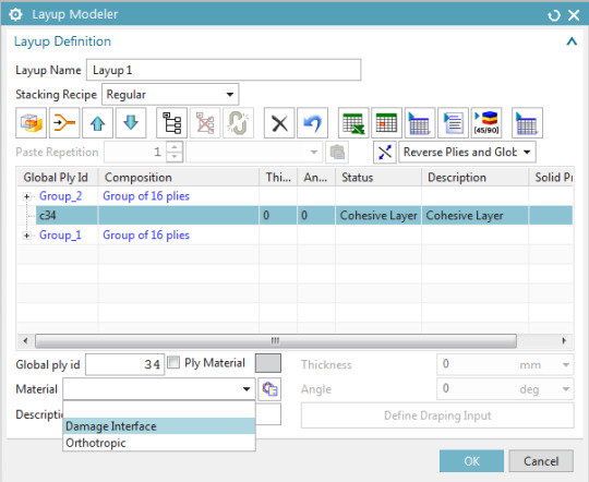
Figure 5: Assign the created material to the cohesive layer
Setting up the simulation
1. Create the simulation and solution
Create a new Simcenter Multiphysics simulation and solution, keeping “Automatically Create Step or Subcase” checked:

Figure 6: Create a Simcenter Multiphysics solution
In the “Solution Control” tab, check the “Material Nonlinearity” box (See Figure 7).

Figure 7: "Solution Control" tab
From the “Result Options” tab, edit the “Structural Output Request” (see Figure 8):
Set the “Damage” of the Cohesive Element Results to “DAMAGE”.
Set the “Output Medium” of the Cohesive Element Results to “PLOT”.

Figure 8: "Output Request" menu
2. Define the boundary conditions
The -X face of the coupon is completely fixed, while Mode 1 delamination is solicited by defining equal and opposite 1 mm displacements to the top and bottom nodes of the +X face. This is shown in Figure 9 and Figure 10.

Figure 9: Fixed Constraints and Enforced displacements

Figure 10: Constraints in Sim Navigator
3. Define the time step
To define the time integration parameters, select the “Step – Nonlinear Static” node in the sim navigator, then right-click “Edit”, and in the “Time Step Definition” tab, set the “End Time” to 1 sec and the “Number of Increments” to 20. See Figure 11 and Figure 12.

Figure 11: Edit the time integration controls

Figure 12: Specify solution time and time step
4. Run the simulation and animate the damage results
Next, launch the solution and subsequently load the “Cohesive Damage [EXPO] – Element Nodal V1” results. In the “Post Processing Navigator – Fringe Plot”, display only the cohesive elements, as shown in Figure 13:

Figure 13: Display the cohesive elements
To animate the results across all the iterations of the nonlinear solution, use the “Animate” button in the ribbon bar. A damage value of 1 indicates a complete delamination of the plies. Use the animation options shown in Figure 14:

Figure 14: Animate the results

Figure 15: Animation of the delamination results.
1 note
·
View note
Text
ArcGIS Earth adds Geocoding in ArcGIS Online, raster and 3D model insert, and an Automation API
ArcGIS Earth 1.6 focused on expanding the range of workflows that users can accomplish with Earth to allow more enterprise productivity. The release of ArcGIS Earth 1.6 enables users to batch geocode address files against ArcGIS Online, adds local raster and 3D model insert support, and opens the possibility to start to integrate Earth with other applications on a user’s machine. Earth also continues to grow the range of configuration that can be defined during the setup and installation process.
What’s New
New Data Support
3D Models
Local Raster Imagery
New Functions
Ability to batch address geocode against ArcGIS Online
Ability to organize startup layers into groups
Updated pop-up editor for drawing elements
Ability to turn off automatic calls to ArcGIS Online for secure environments
Enhancements
Improved UI/UX for CSV and TXT files
Ability to select multiple fields or single field for batch geocoding
Ability to rematch failed geocoding address items
Improved configuration for pop-up content with CSV and TXT
Improved color picker for drawing elements, CSV and TXT, and shapefiles
More icons and a new loading data indicator
New Automation API
Ability to control camera navigation and fly animations, including get camera information and set camera position
Ability to control data operations including add data and delete layers from workspace
Ability to take a snapshot of the view
In the 1.6 release, users can now add 3D models including:
3Ds Max 3DS (.3ds)
Collada (. dae)
Autodesk (. fbx)
AutoCAD DXF (.dxf)
Wavefront Object (.obj)
DirectX X (.x)
Stanford Polygon Library (.ply)
Stereolithography (. stl)
Industry Foundation Classes (IFC/Step) (.ifc)
Like other content added in ArcGIS Earth, the 3D model is inserted into the Table of Contents. There it’s properties can be edited in a similar manner to ArcGIS Earth’s draw features using the General, View, and Info tabs. A 3D model’s name, position, altitude mode, scale, heading, tilt, and roll properties can all be configured under the General Tab. The View tab allows users to set the fly-to view as well as reset to center, while the Info tab allows the user to type in descriptions. With 1.6 the Info tab has been made even more user-friendly allowing the use of Rich Text or HTML that will be displayed as a pop-up window when the model is clicked. Users can get very creative with this feature and convey cool and interactive information! Users will also be happy to know that ArcGIS Earth is begging to support exporting models to KMZ, beginning with COLLADA (*.dae)!
New raster data types have also been added. These include:
*.img
*.tif
*.png
*.dt0, dt1, dt2
*.jpg, jp2, j2k
*.hgt
*.ntf
*.gen
These new raster data types can be added as a service or as a local file. Once added to ArcGIS Earth, users can adjust the raster’s appearance by changing the transparency, brightness, contrast, and gamma values – capabilities already provided in ArcGIS Earth with image services. Users will also be able to choose and include these raster datatypes as basemaps!
ArcGIS Earth 1.6 also makes it easier for administrators. By adding start-up layer groups to ArcGIS Earth’s config.xml file, organizations with large amounts of data layers can now be categorized in the TOC. Earth’s config.xml allows administrators to preset many of ArcGIS Earth’s settings. For users behind a firewall, ArcGIS Earth 1.6 includes the ability control ArcGIS Online requests when ArcGIS Earth is launched, grant access to API functionality and new with 1.6, enable authenticated postionURL services (a parameter that allows admins to enter a URL with encoded values that will be recognized by Earth).
In ArcGIS Earth 1.6 you can use portal geocoder and world geocoder from ArcGIS Online during CSV/TXT geocoding. When searching in ArcGIS Earth, users can always use any geocoder from the portal.
Also with ArcGIS Earth 1.6 are UI\UX improvements for CSV and TXT files. Importing CSV/TXT includes the ability to select multiple fields or a single field for batch geocoding, as well as the ability to rematch failed geocoding address items. Additional user interface improvements include an improved color picker and new icon options for CSV/TXT as well as drawing elements and shapefiles.
Our user community has been providing some great feedback – Please keep them coming!
Download and try out the new features and much more with ArcGIS Earth 1.6 today!
from ArcGIS Blog http://ift.tt/2x9O5We
0 notes
Text
Import DirectX Files & Convert DirectX 3D Model to 3D Supported Formats inside .NET Apps
What’s new in this release?
Aspose team is pleased to announce the release of Aspose.3D for .NET 17.02.0. The new version adds support of importing DirectX (.x) files. Developers can import DirectX (.x) files (ASCII and Binary) into the Aspose.3D API, and then export them in any supported 3D format. Developers can install Aspose.3D Nuget package in their .NET applications because we publish each version as a NuGet package on the NuGet gallery. The X file format refers to files with the .x file name extension. The DirectX (.x) format is a template-driven format which can accommodate all your 3D gaming needs, from simple mesh’s to complete bone animation characters. Using Aspose.3D API, developers can convert a DirectX (.x) 3D model to 3D supported formats. All supported 3D formats are listed on this page: Save a 3D Document. These help topics will help to know the way of importing an existing X file, Reading a 3D Scene and Specify Load Options of 3D DirectX .x File. This release includes plenty of new features as listed below
Add support of importing the X (binary and ASCII) files.
Enhanced Reading a 3D Scene
Import an Existing PLY File into the Aspose.3D API
Add support of importing the DXF.
Newly added documentation pages and articles
Some new tips and articles have now been added into Aspose.3D for .NET documentation that may guide users briefly how to use Aspose.3D for performing different tasks like the followings.
Save a 3D Document
Reading a 3D Scene
Overview: Aspose.3D for .NET
Aspose.3D for .NET is a feature-rich component and class library for .NET that empowers Mono and .NET application including ASP.NET, Windows Forms and Web Services to connect with prevalent 3D document formats automatically without the 3D modeling and rendering software being installed on the server. It supports FBX (ASCII, Binary) and STL (ASCII, Binary) file formats and developers can easily create, read, convert, modify and control the substance of these 3D document formats using Aspose.3D API.
More about Aspose.OCR for .NET
Homepage of Aspose.3D for .NET
Download Aspose.3D for .NET
#importing DirectX files#export DirectX to 3D format#Save a 3D Document#Reading a 3D Scene#import existing X file#.NET 3d API#.NET 3D Component
0 notes
Text
How to create 3D solid mesh for a sandwich composite laminated car hood using Simcenter Laminate Composites
Quick Overview
youtube
Sandwich panels are prevalent in many structural applications. The panel facesheets react the membrane and bending loads, whereas the core reacts the bulk of the transverse shear loads. Therefore, you may use the solid mesh to get better results in the ply out-of-plane direction to evaluate delamination and also investigate the local sandwich behavior near the tapered core.
This tips and tricks shows how to use Simcenter Laminate Composites to create a 3D mesh of a tapered laminated composite sandwich car hood.

Figure 1: Car hood CAD model. Top face (left). Bottoms face (Right).
Steps
1- Create a 2D mesh
First, we create the parent 2D mesh on the car hood top face and that will be extruded to a 3D mesh. To create the 2D mesh, go to Home tab, under Mesh group, select 2D Mesh command to create a 2D mesh on the top face of the car hood.

Figure 2: Create 2D mesh on the car hood top face.
We use a ply-based approach to define layups’ global plies and how they drape on the model. In the Laminate tab, select Laminate Physical Property. In the Laminate Modeler dialog, set the stacking recipe to Inherited from layup and click OK.

Figure 3: Create a Laminate Physical Property.
Let’s assume a simple quasi-isotropic [0/45/-45/90]s layup with a 12.7 mm thick foam core, which is tapered around the perimeter of the hood.
In the Laminate tab, select Global Layup and then in the Layup Modeler dialog, select the Import Layup Using Shorthand Format.

Figure 4: Create a Global Layup.
In the shorthand Format dialog enter the layup as [0/45/-45/90/0’]_s, set the Thickness to 0.125mm and the Material to CFRP.

Figure 5: Input the layup using shorthand format.
In the Layup Modeler dialog, verify the Stacking Recipe is Symmetric with core, change the material for Ply 5, which is the core, to foam and change its thickness to 12.7mm.

Figure 6: Layup definition in the Layup Modeler dialog.
To drape the plies, shift-select plies 1 to 4 and click on the Define Draping Input command. In the Draping Data: Layup Files dialog, select the entire top face of the car hood, and click OK.

Figure 7: Drape the plies on the car hood.
In the Layup Modeler dialog, select the core ply and then click on Define Draping Input command. This time select the face(s) on which the core ply is going to be laid up.

Figure 8: Drape the core ply.
The 2D layup is now defined and properly draped. To automatically inflate this layup to a 3D mesh, go to the Laminate tab, select Extrude Laminate command.

Figure 9: Extrude laminate command.
In the Laminate 2D-to-3D Extrusion dialog, under the Settings group, select all the faces of the car hood on which the 2D laminate is draped.

Figure 10: Laminate Extrusion settings.
Under the Sandwich Inflation group, Set the Top Skin Mesh and Bottom skin Mesh to 3D and select the core ply from the list. Here you can also optionally set the Number of Core Element Layers. Click Ok.
As shown in Figure 11, the 3D solid mesh for the car hood is created. Drop-off resin elements are automatically created where the core tapers. The drop-off resin elements are created as a separate mesh entity. You can drag the resin meshes to be under the same collector as the core meshes.

Figure 11: 3D mesh created for the laminated composite car hood.
0 notes