#Low Power High Speed Microcontroller
Explore tagged Tumblr posts
Visit Tumblr Blog
Explore Tumblr blogs with no restrictions, modern design and the best experience.
Last Seen Tumblr Blogs


Fun Fact
The average Tumblr user visits about 67 pages every month.
Text
Low Power High Speed Microcontroller, Programmable pic microcontrollers
STM32F Series 2 MB Flash 256 KB SRAM 180 MHz 32-Bit Microcontroller - BGA-176
0 notes
Text
https://www.futureelectronics.com/p/semiconductors--microcontrollers--16-bit-general-purpose/mc812a4cpve8-nxp-6048193
General purpose microcontrollers, lcd microcontroller, Pic microcontrollers
MC812A4 Series 1 kB RAM 16-Bit Low Power High Speed Microcontroller - LQFP-112
#Microcontrollers#16 bit General Purpose#MC812A4CPVE8#NXP#lcd microcontroller#Pic microcontrollers#What is a wireless microcontroller#16 bit special embedded microcontroller#16-Bit Low Power High Speed Microcontroller
1 note
·
View note
Text
Low Voltage Relays Explained: Types, Functions, and Applications

In the complex world of electrical systems, relays play a crucial role in ensuring safety, efficiency, and automation. Among these, low voltage relays stand out as versatile components that manage and protect circuits operating below 1000 volts. Whether in industrial automation, residential power distribution, or commercial infrastructure, these devices act as the nerve center of electrical control and protection.
In this comprehensive guide, we will break down what low voltage relays are, explore their types, explain their functions, and highlight their diverse applications across industries.
What Are Low Voltage Relays?
A low voltage relay is an electrically operated switch that uses a small control voltage (typically below 1000V AC or DC) to switch larger electrical loads on and off. These relays act as intermediaries between control circuits and power circuits, providing isolation, control, and protection.
Unlike manual switches, relays automate the process of circuit management, responding to electrical signals, fault conditions, or system commands without human intervention.
Types of Low Voltage Relays
Low voltage relays come in several forms, each tailored to specific tasks within an electrical system. Here are the main types:
1. Electromechanical Relays (EMRs)
· Use a coil and a movable armature to open or close contacts.
· Provide physical isolation between input and output.
· Common in traditional control panels and basic automation.
2. Solid-State Relays (SSRs)
· Use semiconductors (like thyristors or triacs) instead of mechanical contacts.
· Offer silent operation, faster switching, and longer lifespan.
· Ideal for high-speed applications and environments requiring low maintenance.
3. Overload Relays
· Specifically designed to protect motors and equipment from sustained overcurrent.
· Available as thermal overload relays (using bimetallic strips) or electronic overload relays (using sensors and processors).
4. Time Delay Relays
Provide a deliberate time lag between the relay receiving a signal and switching.
Used in motor control circuits, lighting systems, and sequential operations.
5. Overcurrent and Short-Circuit Relays
· Detect and react to current exceeding preset thresholds.
· Essential for system protection against faults and overloads.
6. Voltage Monitoring Relays
· Monitor voltage levels and trip when voltages fall below or rise above safe limits.
· Protect sensitive devices from under voltage and overvoltage conditions.
Functions of Low Voltage Relays
Low voltage relays serve multiple vital functions in electrical systems:
1. Switching and Control
Relays control the opening and closing of power circuits in response to low voltage signals from controllers, timers, or sensors. This enables remote and automated control of large electrical loads.
2. Protection
Relays detect abnormal conditions like overloads, overcurrent, under voltage, and phase failures. When such conditions arise, they disconnect the affected circuit to prevent equipment damage or fire hazards.
3. Isolation
They electrically isolate control circuits (usually low voltage, low current) from power circuits (high voltage, high current), ensuring safety and reducing interference.
4. Signal Amplification
A small control signal (from a PLC, sensor, or microcontroller) can trigger a relay to switch much larger loads, effectively amplifying the control power.
5. Automation and Sequencing
In complex systems, relays help sequence operations by ensuring that processes occur in the correct order and at the right time intervals.
Applications of Low Voltage Relays
Low voltage relays are the backbone of automation and protection in various industries. Here are some key application areas:
Industrial Automation
· Control of motors, pumps, conveyor belts, and production lines.
· Use in programmable logic controllers (PLCs) and distributed control systems (DCS).
Power Distribution Systems
· Protect electrical panels from overload and short circuits.
· Monitor voltage and current levels in distribution boards.
Building Automation
· Lighting control systems.
· HVAC (heating, ventilation, and air conditioning) systems.
· Elevator and escalator controls.
Renewable Energy Systems
· Manage and protect solar inverters, battery banks, and wind turbines.
· Automatically disconnect faulty sections to prevent system-wide failures.
Data Centers and IT Infrastructure
· Ensure stable power supply to servers and networking equipment.
· Protect sensitive electronics from voltage fluctuations.
Transportation
· Railways, metros, and automotive applications for control and safety circuits.
Home Appliances
· Found in washing machines, microwave ovens, and HVAC units to automate functions and provide protection.
Advantages of Using Low Voltage Relays
· Enhanced Safety: Isolate control and power circuits, reducing electrical shock risks.
· Automation Ready: Easily integrated into automated systems for smarter operation.
· Cost-Effective Protection: Safeguard expensive equipment from damage due to electrical faults.
· Versatile: Available in many forms to suit different voltage levels, currents, and response times.
· Reduced Maintenance: Especially with solid-state relays, which have no moving parts.
Future Trends: Smart Relays and IoT Integration
As industries move toward smart grids and Industry 4.0, low voltage relays are also evolving:
· Digital relays offer programmable settings, self-testing, and event recording.
· IoT-enabled relays can send status updates and alerts to centralized monitoring systems.
· Energy-efficient designs reduce power consumption while providing reliable protection.
Conclusion
Low voltage relays are indispensable in modern electrical engineering, seamlessly combining protection, control, and automation. From safeguarding your home appliances to managing the power in a sprawling industrial plant, these devices ensure that electrical systems run smoothly and safely.
Understanding the different types, functions, and applications of low voltage relays empowers system designers, engineers, and even DIY enthusiasts to build safer and more efficient electrical setups.
As technology advances, the role of these small but mighty devices will only grow, driving the future of safe, smart, and automated power systems.
9 notes
·
View notes
Text
I was referencing the things put forth by OP, in order:
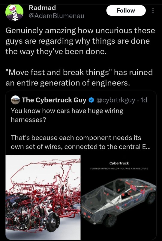
Huge wiring harnesses simplified: Cybertruck Guy and Radmad are both wrong, for different reasons.
Current industry standards don't have separate wires for each individual switch or control, either. They group several switches, lights, etc. that are nearby together, run them into a microcontroller, and put that controller on a vehicle bus. Currently that's usually a CAN (redundant, fault-tolerant) or LIN (neither, but much simpler) bus. This drastically simplifies wiring harnesses.
The main thing Tesla has done is change the DC voltage for that bus from 12 V to 48 V nominal. Since power is voltage times current, and wire thickness is dependent on current, this cuts about half the copper mass out of the power lines in the harness. The other (data) lines were already using smaller wires. The industry has been flirting with a 48V bus for around two decades by now; Tesla just went and did it and dealt with the engineering problems when they popped up. And this is a rare case where "they're a bunch of Silicon Valley nerds" may have helped: datacenters have been using 48V DC for in-rack power delivery for decades, so they had more familiarity with it than Detroit.
They've also adopted single-pair Ethernet (1000base-T1) for the high-speed entertainment data links. This technology has been in the industry since late 2016. It's usually integrated directly onto the custom ICs in ECUs. I remember another thread like this with a tweet where someone was complaining about the fragility of RJ-45 plugs and how that's disqualifying for a vehicle, and he's right, but single-pair Ethernet does not use those jacks; it's integrated into wiring harnesses with everything else.
Astronauts laded on the moon with altitude markers hand etched on the window: That was a backup system dramatized by the Apollo 13 movie. They had an inertial navigation system, like aircraft do, as their primary navigation.
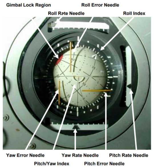
Oh, and it's attitude, not altitude. Very different concepts that folks should not mix up.
Can't get a rocket off the pad without blowing up: Neither could NASA their first few years. Meanwhile SpaceX had 98 successful orbital flights last year, and they can reuse their boosters (the record is 18 times). But that's way off topic.
Tesla Model Y broke: It's not news when non-Teslas lose power steering, apparently. And I've had cars that took many more than three appointments to fix. We can throw around anecdata all day.
Series wiring like Christmas lights: Come on, you've got no basis for that.
It's like the Titan sub: Sigh. Really?
Okay, now to the RDN link:
the vehicle’s angular design and stainless steel body could pose danger to other road users
Absolutely true. Also true of almost every luxury pickup truck on the market. One example:

I'm all for figuring out some kind of regulatory regime to rein this in. Or maybe a modification of liability rules and increased insurance coverage minimums.
“The big problem there is if they really make the skin of the vehicle very stiff by using thick stainless steel, then when people hit their heads on it, it’s going to cause more damage to them,”
True, but it's not that thick or stiff; the speaker was speculating. Other have pointed out that "we shot it with a Tommy gun" is a lousy test because the bullets are rather low velocity. If you watch the side impact crash test, you can see the side panels visibly flexing.
And right after that, an IIHS rep said, “IIHS hasn’t evaluated the Cybertruck. The discussions we’ve seen so far appear to be based on speculation. I would add that our experience with Tesla is that they aim for the highest safety ratings in IIHS tests. We have no reason to expect anything different with the Cybertruck.”
The biggest problem with Teslas, from insurance companies' perspectives, has been that airbag-deployed collisions tend to result in totaling the vehicle more often than in other cars. Occupant safety, on the other hand, seems to be better than average. We've seen people walk away from their Model 3s after they got T-boned by speeding pickups (60-ish MPH in a 30 zone). We know this from accident reconstruction and camera data.
There's a linked video in the article comparing the Tesla Cybertruck collision to a Dodge Ram 1500. There are several others like it on YouTube (I saw one that had six trucks in it, all synced up). They all have the same flaw: they're comparing different crash types. The Cybertruck is doing a full frontal crash, where you drive the vehicle into a solid, immovable wall, while the others are moderate overlap crashes, where the hood goes over the obstacle and only the left 1/3 of the vehicle is obstructed, so the engine can deflect to the sides instead of going into the firewall and then the passenger compartment. The Cybertruck, of course, does not have a large engine in that space; it's mostly cargo storage. And we can clearly see it crumpling and the front wheel moving outward instead of back into the passenger compartment, like practically all cars do now.
(Some folks like to point out how the rear wheel breaks away, too: this is expected because it's a steering wheel, since the Cybertruck has four-wheel steering, and uses the same suspension technology as the front, instead of connecting the rear wheels more directly to the rear axle like most vehicles. Not completely directly, though, like the Chevy Corvair's swing axles. In any case, kinetic energy breaking the rear wheels off like that is energy that isn't compromising the cabin.)
The article addresses the "lack" of crumple zones:
Samer Hamdar, a George Washington University auto safety professor, told Reuters that while a lack of crumple zones concerned him, there could be other factors that accounted for it. “There might be a possibility of shock-absorbent mechanism that will limit the fact that you have a limited crumple zone,” Hamdar said.
I'm not going to speculate about crumple zones beyond the above ("the cargo area collapses, taking some energy with it; we have to see if that's enough to call a crumple zone, but it's not nothing") until someone tears one down and documents it. But crumple zones aren't the only means of keeping kinetic energy out of the passengers.
The rest of the article goes back to concerns about pedestrian safety, which seem to be the main substantive concern, and is noted at the end of this video:
youtube
And again, pedestrian safety is an industry-wide problem. We need another Ralph Nader, but demonizing Tesla alone (god it's so easy, Elon is such an asshole) only gives cover to the rest of the industry. And none of the tweets in OP's post spoke of this.


42K notes
·
View notes
Text
The Future of Warehouse Robots: AI Meets Electronics Design

The future of warehouse robots lies in the powerful fusion of AI integration and advanced electronics design — enabling smarter, faster, and more autonomous logistics operations. Electronics design ensures robots are compact, reliable, and capable of processing massive amounts of real-time data, while AI adds the intelligence to learn, adapt, and optimize warehouse tasks like sorting, picking, and navigating.
If you’re looking to understand what’s driving the next wave of innovation in warehouse automation, this article explains how AI and electronics are shaping the most efficient, intelligent robots ever built for industrial logistics.
Why AI and Electronics Design Are Game Changers for Warehouse Robots
Warehouses are fast-paced environments where precision, speed, and adaptability are critical. Traditional automation helped, but it lacked flexibility. Today, AI-driven warehouse robots powered by advanced electronics design are bridging that gap.
Here’s how the synergy works:
Electronics design enables lightweight, high-performance robotic systems with smart sensors, efficient power management, and robust connectivity.
AI integration processes that data to make decisions, learn from patterns, and continually improve task efficiency.
Together, they create autonomous systems capable of handling unpredictable inventory challenges in real time — faster and more reliably than ever.
Core Technologies Behind Modern Warehouse Robots
1. Smart Electronics Design
At the heart of every capable warehouse robot is a custom-designed electronic system, which includes:
Embedded microcontrollers and PCBs that control movement and communication
Sensor arrays for object detection, spatial awareness, and load tracking
Battery and power systems optimized for long shifts and fast recharging
Wireless modules for seamless data flow and remote updates
Electronics design focuses on reliability, low power consumption, and miniaturization — making robots both powerful and space-efficient.
2. AI Integration
AI gives robots the intelligence they need to:
Identify and classify objects with computer vision
Plan routes dynamically using real-time mapping and SLAM (Simultaneous Localization and Mapping)
Predict demand and optimize picking paths
Detect anomalies or safety risks without human intervention
This AI capability is only possible when backed by well-integrated, high-speed electronics that deliver real-time data and process it on-board or via edge computing.
Key Applications in Warehouses
Autonomous Mobile Robots (AMRs)
AI-powered AMRs use advanced sensors and AI algorithms to navigate warehouse floors, avoiding obstacles, rerouting in real-time, and managing deliveries.
Electronics role: Precise motor control, LiDAR/ultrasonic sensor support, real-time feedback, and robust safety circuits.
Robotic Picking Systems
Robots with grippers or suction arms can now pick and sort items of various shapes, guided by AI vision systems.
Electronics role: High-speed processors, smart camera modules, and force-sensitive feedback loops.
Inventory Monitoring Robots
Some robots autonomously scan shelves for stock levels, damaged goods, or misplaced items.

Benefits of AI + Electronics in Warehouse Robots
Greater Efficiency: AI algorithms optimize paths, reduce downtime, and adapt to demand.
Higher Accuracy: Fewer picking or sorting errors thanks to smart sensing and decision-making.
Scalability: Modular electronics design makes it easier to upgrade or expand systems.
24/7 Operation: Smart electronics allow continuous performance with minimal maintenance.
Reduced Labor Costs: Automation reduces reliance on manual labor for repetitive tasks.
Challenges in Design and Integration
While the benefits are clear, building next-gen warehouse robots isn’t without challenges:
Power constraints: AI processing requires energy; electronics must balance performance with battery life.
Sensor fusion complexity: Integrating multiple sensors into one coherent decision-making unit is tricky.
Thermal management: AI chips and motors generate heat, requiring clever thermal design.
Cybersecurity: Wireless communication and AI models must be protected from external threats.
These issues highlight the importance of precise, efficient electronics design and secure, robust AI models.
Future Trends to Watch
Edge AI for Faster Decisions
Instead of sending data to the cloud, AI processing is moving closer to the source (onboard). This requires faster processors and optimized electronics design to deliver near-instant results.
Swarm Robotics
Using multiple robots that coordinate like a hive mind, enabled by AI and synchronized electronics, to cover large warehouse spaces efficiently.
Predictive Maintenance
AI models will monitor wear-and-tear data from sensors to predict breakdowns before they happen — enabled by electronics that track vibration, temperature, or usage cycles.
Interoperability Standards
Future electronics design will focus on plug-and-play compatibility, allowing various robots to work in harmony across brands and platforms.
Real-World Example: AI-Powered Fulfillment Centers
Major players like Amazon and Alibaba already deploy hundreds of AI-integrated warehouse robots designed with advanced electronics systems. These robots:
Navigate high-density shelf areas
Communicate with human operators and other robots
Pick, sort, and deliver packages continuously
Adapt operations based on live order data
This synergy between electronics design and AI has helped these companies achieve previously impossible levels of speed and accuracy.
Final Thoughts
The future of warehouse robots is already taking shape — and it’s built on two pillars: brilliant electronics design and seamless AI integration. Together, they unlock the full potential of automation, allowing warehouse robots to think, adapt, and perform with superhuman precision.
For logistics leaders, engineers, and businesses looking to stay competitive, investing in this technology isn’t optional — it’s a strategic advantage. As innovation accelerates, expect to see even more intelligent, flexible, and efficient warehouse robots shaping the next generation of industrial success.
#ElectronicManufacturing#EMSIndia#PCBDesignChennai#ElectronicsInChennai#PCBAIndia#SMTAssembly#ElectronicsManufacturingServices#PCBManufacturingIndia#ChennaiEMS#ManufacturingInChennai
0 notes
Text
Wagner Engineer: Building the Future Through Precision Engineering

In today’s fast-paced technological landscape, the need for agile, innovative, and expert engineering partners has never been greater. Whether you're a startup with a bold product idea or an established company needing to modernize complex systems, having the right engineering team can make or break your success. One name that has steadily built a reputation for delivering top-tier engineering solutions is Wagner Engineer.
Based in Chicago, Wagner Engineer offers a unique combination of technical depth, design intelligence, and forward-thinking development strategies. With a focus on electrical engineering, firmware, software, and cloud infrastructure, the firm is redefining how small to mid-sized businesses approach high-tech problem-solving.
A Founder with Vision
Wagner Engineer is the brainchild of Dylan Wagner, a University of Illinois alumnus with a background in electrical engineering and a career rooted in high-impact projects. From his early work on sensor-driven technologies to his leadership roles in engineering-intensive industries, Dylan brings both vision and hands-on experience. His approach combines rigorous engineering standards with a passion for innovation and ethical business.
Dylan’s philosophy is simple yet powerful: build well, build right, and do it with integrity. This belief is embedded in Wagner Engineer’s process and culture, and it has helped earn the firm the trust of clients across multiple sectors.
What Wagner Engineer Does Best
Wagner Engineer is not your average engineering consultancy. The company provides a full-stack approach to product and system development, allowing clients to seamlessly integrate various technologies under a single strategy.
1. Electrical and PCB Design
From concept to production-ready boards, Wagner Engineer designs printed circuit boards (PCBs) that are efficient, reliable, and scalable. They consider not just the electrical performance, but also manufacturability, serviceability, and aesthetics—ensuring the board is practical for real-world applications.
Their design services are ideal for companies developing IoT devices, consumer electronics, automation equipment, and more. Whether starting from a napkin sketch or refining a legacy design, Wagner Engineer delivers excellence.
2. Embedded Firmware Development
A great product is only as good as the code running beneath its surface. Wagner Engineer develops embedded firmware that allows electronic systems to operate intuitively and efficiently. Their team is well-versed in programming microcontrollers, managing low-level device communication, and building resilient embedded systems.
From wearables to industrial sensors, their firmware solutions focus on reliability, speed, and long-term performance—core pillars of successful hardware products.
3. Custom Software Development
In addition to hardware and embedded systems, Wagner Engineer builds powerful software tools that bring hardware to life. Whether it’s a user-facing application, an admin dashboard, or a full-featured web platform, the company designs software with clean architecture, responsive interfaces, and robust back-end logic.
Their software development services are tailored for companies seeking intuitive interfaces, real-time analytics, or secure system management tools—all designed with user experience and long-term support in mind.
4. Cloud Infrastructure and Systems Integration
Cloud technologies are no longer optional—they’re essential. Wagner Engineer helps businesses create scalable cloud infrastructure that integrates smoothly with physical devices and software systems. Whether your goal is real-time monitoring, remote device management, or secure data storage, Wagner Engineer has the expertise to deliver.
By designing robust infrastructure and APIs, they enable seamless communication between devices, apps, and servers, empowering businesses to automate, optimize, and scale.
Wagner Engineer’s Advantage
Several attributes distinguish Wagner Engineer in a competitive industry:
Cross-Disciplinary Expertise: Their in-house capabilities span electrical engineering, software, firmware, and cloud—eliminating the silos common in product development.
Client-Centered Design: Every project begins with a deep understanding of the client’s needs, target users, and long-term vision. They don’t just build; they co-create.
Attention to Detail: From wire traces to user workflows, Wagner Engineer prioritizes precision. Their team adheres to best practices at every level.
Agile and Scalable: Whether you’re launching a prototype or rolling out a global product line, Wagner Engineer offers the flexibility to scale up or pivot quickly.
Commitment to Quality: Every deliverable undergoes rigorous testing and quality assurance, ensuring reliability and maintainability.
Serving a Wide Range of Industries
Wagner Engineer has partnered with clients across a variety of sectors, including:
Medical Technology: Where compliance, safety, and precision are paramount
Smart Home and IoT: Devices that connect, communicate, and streamline lives
Industrial Automation: Systems that power manufacturing and logistics
Consumer Electronics: User-focused design that delivers functionality and appeal
Green Tech and Renewable Energy: Supporting the future of sustainable solutions
Their diverse portfolio demonstrates adaptability and deep knowledge across use cases.
Partner Testimonials
Clients frequently cite Wagner Engineer’s responsiveness, technical mastery, and ability to “just get it done.” Many describe the team as an extension of their own, not just a service provider. Their ability to simplify the complex and deliver polished, working solutions—on time and within scope—has earned them repeat business and strong referrals.
How to Connect with Wagner Engineer
If you're ready to transform your ideas into working systems, Wagner Engineer is ready to partner with you. Whether you need help building your first prototype or managing the technical side of a large-scale deployment, they have the tools and talent to help.
📍 Location: 2540 W Grand Ave, Suite 2 PMB 917286, Chicago, IL 📞 Phone: +1 312-288-8764
Wagner Engineer is more than an engineering firm—it’s a strategic partner that blends technical expertise with real-world insight. With services spanning hardware to cloud, they offer a comprehensive toolkit for companies looking to innovate quickly and effectively. Backed by strong leadership and a commitment to doing things the right way, Wagner Engineer is helping shape the next generation of smart, connected technologies.
0 notes
Text
Fast Rectifiers Market Future Trends Shaping Efficiency, Miniaturization, and Power Management Worldwide
The fast rectifiers market is undergoing a significant transformation, driven by a combination of technological innovation, increasing demand from high-speed electronics, and the growing need for efficient power management solutions. Fast rectifiers, known for their ability to switch on and off quickly with minimal reverse recovery time, are vital components in many modern applications, including consumer electronics, automotive systems, industrial machinery, and renewable energy systems. As industries aim for higher performance with lower energy losses, the future trends in this market reflect the intersection of speed, reliability, and sustainability.
Rise in Demand for High-Frequency Applications
One of the major future trends in the fast rectifiers market is the increasing integration of these components in high-frequency circuits. Power supplies, RF systems, and modern digital devices rely on fast rectifiers for smooth performance and noise reduction. As digital infrastructure expands and the Internet of Things (IoT) grows, the need for components that can handle higher switching frequencies efficiently is becoming more prominent. Fast rectifiers are well-suited for this, making them essential for next-gen devices, particularly where compactness and heat reduction are key.
Surge in Electric Vehicles (EVs) and Charging Infrastructure
The global shift towards electric vehicles is significantly influencing the fast rectifiers market. These components are used in onboard chargers, inverters, and other power conversion systems within EVs. As countries increase their EV adoption rates and invest in widespread charging infrastructure, the demand for efficient rectification processes will continue to rise. Fast rectifiers ensure lower heat dissipation and faster power conversion, which are critical for enhancing vehicle performance and charging efficiency.
Moreover, EV manufacturers are now looking to implement silicon carbide (SiC) and gallium nitride (GaN)-based fast rectifiers to achieve higher voltage endurance and better thermal management. This shift towards wide bandgap semiconductors is expected to be a defining trend in the coming years.
Miniaturization and Integration into Compact Devices
With the ongoing miniaturization of electronic devices, there is a growing need for smaller, yet more powerful, components. Fast rectifiers that offer low forward voltage drop and minimal reverse recovery time are increasingly integrated into microcontrollers, power supplies, and wearable technologies. The demand for compact and portable devices such as smartphones, laptops, and smartwatches continues to rise, thereby fueling innovation in fast rectifier designs to support slim profiles without compromising performance.
In this context, the development of surface-mount devices (SMDs) and chip-scale packaging (CSP) has become a key focus area for manufacturers. These packaging technologies allow better thermal efficiency and high-density integration, opening new avenues for fast rectifiers in both consumer and industrial applications.
Integration with Renewable Energy Systems
Fast rectifiers are gaining momentum in renewable energy systems such as solar inverters and wind turbines. These applications require reliable and efficient rectification to convert variable AC input into stable DC output. As the world intensifies its focus on clean energy, the deployment of fast rectifiers in solar power inverters and battery storage systems will grow. They enable high-speed switching and reduce power losses, which is crucial for maximizing energy output in renewable setups.
The trend toward decentralized energy systems, such as rooftop solar and microgrids, also underscores the need for advanced rectification technologies. Fast rectifiers contribute to the reliability and efficiency of these localized energy solutions.
Adoption of Wide Bandgap Semiconductor Materials
Another crucial trend shaping the future of the fast rectifiers market is the adoption of wide bandgap semiconductor materials like SiC and GaN. These materials offer better efficiency, higher thermal conductivity, and faster switching capabilities than traditional silicon. Fast rectifiers using these advanced materials can operate at higher voltages, temperatures, and frequencies—making them ideal for demanding applications like data centers, 5G infrastructure, and aerospace electronics.
While these materials currently come at a higher cost, ongoing research and manufacturing advancements are expected to lower production costs, paving the way for broader adoption across different sectors.
Regional Expansion and Emerging Markets
The fast rectifiers market is witnessing rapid growth not only in developed markets like North America and Europe but also in emerging economies across Asia-Pacific and Latin America. Countries like China, India, and Brazil are investing heavily in infrastructure development, consumer electronics, and renewable energy, which are key application areas for fast rectifiers.
As these regions expand their industrial and electronic manufacturing bases, the demand for reliable and efficient rectification technology will grow, offering new opportunities for global and local manufacturers alike.
Conclusion
Future trends in the fast rectifiers market highlight a promising outlook driven by electric vehicles, renewable energy integration, miniaturization of electronics, and advancements in semiconductor materials. The convergence of speed, efficiency, and compact design continues to shape the evolution of fast rectifiers, making them indispensable in modern power electronics. As industries push towards smarter and greener solutions, fast rectifiers are poised to play a critical role in powering innovation across the globe.
0 notes
Text
Flip Chip Market Progresses for Huge Profits During 2027
Allied Market Research, titled, “Flip Chip Market by Packaging Technology, Bumping Technology, and Industry: Opportunity Analysis and Industry Forecast, 2020–2027,” the flip chip market size was valued at $24.76 billion in 2019, and is projected to reach $39.67 billion by 2027, growing at a CAGR of 6.1% from 2020 to 2027.
Increase in demand for high speed and compact size electronic products has boosted the adoption of flip chip technology in the electronic industry. Internet of Things (IoT) has been gaining popularity, and serves as a key driver of the market. Products used in IoT, such as sensors & actuators, analog & mixed-signal translators, and microcontrollers or embedded processors require efficient and reliable packaging solutions, which can be done using flip chips.
In comparison to customary wire-bond packaging, flip chip offers various benefits such as, superior thermal & electrical performance, substrate flexibility for varying performance requirements, remarkable I/O capability, reduced form factors, and well-established process equipment expertise. Gold bumping technology contributes the second largest share in overall flip chip market. The gold bumping segment is expected to witness sluggish growth rate as compared to other bumping technologies, owing to its high manufacturing cost, fragile construction, and complexities involved in bumping process. In addition, improved heat dissipation of ball grid array type flip chips makes them suitable choice in applications where smaller size chips are preferred without the need for external heat sink.

The solder bumping technology segment garners the third largest share in the global flip chip market. This is attributed to low cost of solder bumping technology and considerably improved bonding efficiency. The rapid downfall of tin lead eutectic solder is attributed by the collective oppose of the usage of lead across the globe, owing to its severe threat to environment. Moreover, being an old technology, it is currently being used in most of the flip chip fabrication. However, its growth rate is expected to decline, due to implementation of government regulations, which restrict the usage of lead in chips due to its hazardous effects to environment.
Flip chip possess the potential to reduce size, weight, and thickness of circuits and increase their signal power and high I/O count, owing to its substantially high spectrum bandwidth and enhanced electrical, thermal, and mechanical properties. The 2.5D IC packaging technology poses several challenges, such as lack of foundries and assembly houses which is supported by 3D IC packaging technology. Thus, flip chip technology have witnessed unawareness of cost-effectiveness & improved performances, which could hamper its adoption in the manufacturing industry.
Asia-Pacific region dominates the flip chip market in terms of number of manufacturer and in terms of consumers. In 2019, reduction in China’s supply chain significantly impacted on companies across the globe and disrupted the electronics value chain. The outbreak of corona virus constrained governments across the globe to force lockdown initiatives which halted many production facilities operations which in tun disrupted the worldwide economy at a significant extent. Moreover, industries such as manufacturing and construction across the globe have witnessed shortage of labors and various hardware components from supplier side. This hindered the market growth to a certain extent, but is further expected to adjust the growth of flip chip market in the coming years.
Key Findings Of The Study
By packaging technology, the 2.5D IC segment dominated the flip chip market growth. However, the 2D IC segment is expected to exhibit significant growth during the forecast period.
Depending on bumping technology, the copper pillar segment led the flip chip market share in 2019. However, the gold bumping segment is expected to display highest growth during the forecast period.
On the basis of industry, the electronics segment witnessed significant growth in the flip chip market trends. However, the IT & telecommunication segment is anticipated to dominate the market during the forecast period in the industry.
Region wise, Asia-Pacific dominated the flip chip market size in 2019. However, North America is expected to witness significant growth in terms of revenue in the coming years owing to high demand for smart electronics in this region.
Some of the key market players profiled in the flip chip industry include 3M, AMD, Inc., Amkor Packaging Technology, Inc., Apple, Inc., Fujitsu Ltd, IBM Corporation, Intel Corporation, Samsung electronics Co., Ltd, TSMC, Ltd,, and Texas Instruments, Inc. Major players operating in this market have witnessed significant adoption of strategies such as business expansion and partnership to reduce supply and demand gap. With the increase in digitalization initiatives and industry revolution across the globe, major players have collaborated on their product portfolio to provide differentiated and innovative products.
0 notes
Text
How C and C++ Power the Modern World: Key Applications Explained
In an era driven by digital innovation, some of the most impactful technologies are built upon languages that have stood the test of time. Among them, C and C++ remain foundational to the software ecosystem, serving as the backbone of countless systems and applications that fuel the modern world. With exceptional performance, low-level memory control, and unparalleled portability, these languages continue to be indispensable in various domains.
Operating Systems and Kernels
Virtually every modern operating system owes its existence to C and C++. Windows, macOS, Linux, and countless UNIX variants are either fully or partially written in these languages. The reason is clear—these systems demand high efficiency, direct hardware interaction, and fine-grained resource control.
C and C++ programming applications in OS development enable systems to manage memory, execute processes, and handle user interactions with minimal latency. The modular architecture of kernels, drivers, and libraries is often sculpted in C for stability and maintainability, while C++ adds object-oriented capabilities when needed.
Embedded Systems and IoT
Embedded systems—the silent enablers of everyday devices—rely heavily on C and C++. From microwave ovens and washing machines to automotive control systems and industrial automation, these languages are instrumental in programming microcontrollers and real-time processors.
Due to the deterministic execution and small memory footprint required in embedded environments, C and C++ programming applications dominate the firmware layer. In the rapidly expanding Internet of Things (IoT) landscape, where devices must function autonomously with minimal energy consumption, the control and optimization offered by these languages are irreplaceable.
Game Development and Graphics Engines
Speed and performance are paramount in the gaming world. Game engines like Unreal Engine and graphics libraries such as OpenGL and Vulkan are built in C and C++. Their ability to interact directly with GPU hardware and system memory allows developers to craft graphically rich, high-performance games.
From rendering photorealistic environments to simulating physics engines in real time, C and C++ programming applications provide the precision and power that immersive gaming demands. Moreover, their scalability supports development across platforms—PC, console, and mobile.
Financial Systems and High-Frequency Trading
In finance, microseconds can make or break a deal. High-frequency trading platforms and real-time data processing engines depend on the unmatched speed of C and C++. These languages enable systems to handle vast volumes of data and execute trades with ultra-low latency.
C and C++ programming applications in fintech range from algorithmic trading engines and risk analysis tools to database systems and high-performance APIs. Their deterministic behavior and optimized resource utilization ensure reliability in environments where failure is not an option.
Web Browsers and Rendering Engines
Behind every sleek user interface of a web browser lies a robust core built with C and C++. Google Chrome’s V8 JavaScript engine and Mozilla Firefox’s Gecko rendering engine are developed using these languages. They parse, compile, and execute web content at blazing speeds.
C and C++ programming applications in browser architecture enable low-level system access for networking, security protocols, and multimedia rendering. These capabilities translate into faster load times, improved stability, and better overall performance.
Database Management Systems
Databases are at the heart of enterprise computing. Many relational database systems, including MySQL, PostgreSQL, and Oracle, are built using C and C++. The need for high throughput, efficient memory management, and concurrent processing makes these languages the go-to choice.
C and C++ programming applications allow databases to handle complex queries, transaction management, and data indexing with remarkable efficiency. Their capacity to manage and manipulate large datasets in real time is crucial for big data and analytics applications.
C and C++ continue to thrive not because they are relics of the past, but because they are still the most effective tools for building high-performance, scalable, and secure systems. The diversity and depth of C and C++ programming applications underscore their enduring relevance in powering the technologies that shape our digital lives. From embedded controllers to the engines behind global finance, these languages remain quietly omnipresent—and unmistakably essential.
0 notes
Text
12-bit 5MSps SAR ADC IP Core by T2M
T2MIP, high-performance 12-bit successive approximation register (SAR) ADC designed for precision, speed, and ultra-low power operation. This new IP core achieves conversion rates up to 5 mega samples per second (MS/s), making it ideally suited for next-generation applications that require high-speed data acquisition with minimal power consumption.
This cutting-edge 12-bit SAR ADC IP core is specifically engineered to meet the demanding requirements of modern SoC (System on Chip) and ASIC (Application-Specific Integrated Circuit) designs. It offers a unique balance of high-resolution data conversion, excellent dynamic performance, low power consumption, and flexible configuration options. These attributes make it a perfect fit for a variety of industries including industrial automation, precision measurement systems, wireless communications, and advanced microcontroller-based applications.
The need for energy-efficient, high-precision analog interfaces continues to grow across a wide range of industries. From portable industrial devices and battery-powered sensors to high-speed communication systems and automotive control units, designers increasingly require ADCs that not only deliver performance but also minimize energy draw. T2MIP’s new SAR ADC core directly addresses this need by providing exceptional signal quality and flexible operating modes while maintaining ultra-low power consumption.
The 12-bit resolution ensures accurate signal quantization, while the 5MS/s sampling rate makes the core well-suited for fast signal processing tasks. This performance is achieved without compromising power efficiency, a feature critical for embedded systems and IoT devices where power budget is often a limiting factor.
Key Performance Metrics
One of the standout features of T2M’s new SAR ADC IP is its high dynamic performance. The converter delivers a Signal-to-Noise and Distortion Ratio (SINAD) of 70 dB and a Total Harmonic Distortion (THD) of -72 dB, which translates to an Effective Number of Bits (ENOB) of 11.3 bits. This makes it ideal for applications requiring high fidelity and accurate representation of analog signals.
Design flexibility is another cornerstone of this IP core. It supports multiple input modes—both single-ended and differential—and can handle up to four input channels. This allows designers to tailor the ADC’s input architecture to their specific system requirements, whether that involves sensing multiple voltages or improving common-mode noise rejection.
Furthermore, the ADC supports selectable resolution modes—8-bit, 10-bit, and 12-bit—allowing developers to trade off between precision and power consumption as needed. Conversion modes include both single conversion and continuous operation, providing adaptability for event-driven or real-time sampling use cases.
One of the most notable innovations in this SAR ADC IP core is its scalable power consumption architecture. In idle mode, it draws zero static (DC) power, and its dynamic power consumption is directly proportional to the clock frequency. This intelligent power scaling makes it ideal for energy-sensitive applications where processing loads vary over time.
In addition to its baseline low-power operation, the IP core also includes extended power management modes. Designers can select between low-noise and ultra-low power modes depending on the performance priorities of the system. For example, battery-powered sensors can operate in low-power mode to extend life, while instrumentation systems can switch to low-noise mode for increased accuracy.
The ADC operates at ultra-low voltages, with an analog supply range from 3.3V down to 1.8V, and a digital supply of just 1.1V. This wide supply compatibility ensures the core can be easily integrated into modern low-voltage SoC platforms without the need for costly voltage level shifters or regulators.
Key Features:
12-bit Resolution with up to 5MS/s Conversion Rate
High Dynamic Performance: SINAD of 70dB, THD of 72dB, and ENOB of 11.3 bits
Multiple Input Modes: Supports both single-ended and differential configurations with up to 4 input channels
Zero DC Power with scalable consumption tied to clock frequency
Selectable Resolution: Operates in 8, 10, or 12-bit modes
Multiple Conversion Modes: Continuous and single conversion modes supported
Extended Sampling & Power Modes: Includes low-power and low-noise modes for tailored performance
Flexible Reference Options: External and optional internal reference support
Ultra-Low Voltage Operation: Analog supply from 3.3V to 1.8V; Digital supply at 1.1V
Advanced Functions: Self-calibration, optional hardware averaging, window watchdog
These advanced features not only improve performance but also simplify the overall design and reduce development time by eliminating the need for external supporting logic in many applications.

Ideal Applications and Use Cases
This SAR ADC IP core is highly suitable for applications requiring compact, power-efficient, and high-performance data conversion. Common use cases include:
Microcontrollers and Embedded Systems: Extend battery life while maintaining accurate analog signal capture in portable electronics, wearables, and sensor nodes.
Industrial Instrumentation: Achieve precision measurements in multichannel monitoring and control systems with minimal power draw.
Broadband Wireless Systems: Convert analog signals at high speed with excellent dynamic range, aiding in RF baseband processing and signal analysis.
Automotive Electronics: Integrate with automotive MCUs for tasks like battery monitoring, motor control, and advanced driver-assistance systems (ADAS).
By addressing the core challenges of low power, high resolution, and easy integration, this ADC IP enables semiconductor manufacturers and system developers to accelerate product development without compromising performance.
Licensing and Availability
T2MIP’ new 12-bit, 5MS/s SAR ADC IP core is available immediately for licensing. semiconductor ip is delivered with comprehensive documentation, test benches, and integration support to ensure a smooth implementation into your design flow. Interested in evaluating or licensing the core can visit t-2-m.com or contact T2M directly at [email protected]
1 note
·
View note
Text
Rethinking Power: The Real Story Behind IGBT Rectifiers
In a world that increasingly runs on precise, clean, and efficient power, the components managing electrical conversion have quietly evolved into silent heroes. Among them, IGBT rectifiers are not just electronic components—they're the backbone of modern industrial energy management.
But let’s take a step back.
When most people think of rectifiers, their minds go to clunky, heat-generating boxes in power rooms. When they hear “IGBT,” they might vaguely associate it with transistors or semiconductors. But the convergence of IGBT technology with rectification isn't just a minor engineering upgrade—it's a game-changer for how we design everything from EV chargers to steel plants.
Let’s explore this through a fresh lens—not just what IGBT rectifiers are, but why they matter, how they work, and what makes them irreplaceable in high-performance environments.
What Are IGBT Rectifiers, Really?
At the core, rectifiers convert AC (alternating current) to DC (direct current). That’s not new. What is new is the use of Insulated Gate Bipolar Transistors (IGBTs) in that process.
Traditionally, rectification was handled using diodes and thyristors. These worked well but had limitations in speed, control, and efficiency. Enter IGBTs—a hybrid semiconductor device combining the fast switching of a MOSFET with the high voltage handling of a bipolar transistor.
So, IGBT rectifiers are essentially intelligent rectification systems. They provide:
Precision: Regulated, ripple-free DC output.
Efficiency: Higher energy conversion with minimal heat loss.
Control: Real-time adaptability in load conditions.
Compact Design: Less bulky compared to traditional systems.
Think of it as the difference between flipping a light switch and using a dimmer with programmable automation. That’s the leap IGBT tech gives to rectifiers.
Why Now? Why IGBT Rectifiers Matter More Than Ever
We're in the midst of several overlapping revolutions:
The EV boom needs ultra-fast charging with precise voltage/current control.
The renewable energy surge requires smart inverters and converters to store and balance variable power.
Smart factories and Industry 4.0 demand real-time, programmable power systems that talk to the cloud.
IGBT rectifiers are the perfect fit for this new energy landscape.
Let’s say you’re running a manufacturing unit that relies on variable frequency drives (VFDs), robotic arms, and programmable logic controllers (PLCs). Traditional rectifiers might get the job done, but IGBT-based systems will optimize your power usage, reduce downtime, and offer predictive maintenance insights. In short, they don’t just work—they think.
Key Advantages of IGBT Rectifiers: Beyond the Basics
High Power Factor & Low Harmonics Unlike older thyristor-based setups, IGBT rectifiers operate at higher frequencies and reduce total harmonic distortion (THD), making them grid-friendly and compliant with IEEE-519 standards.
Regenerative Capability IGBT-based rectifiers can feed excess energy back into the grid or battery systems, increasing overall energy efficiency—something that’s becoming essential in closed-loop industrial applications.
Compact, Modular Designs With IGBT rectifiers, system integrators can fit more power in less space. That’s critical in EV charging stations, medical equipment, and aerospace technologies.
Real-Time Digital Control Thanks to microcontroller-based architecture, these rectifiers can be monitored, tuned, and diagnosed remotely. Maintenance becomes smarter, faster, and safer.
A Human Story: Real-World Use Case
Let’s humanize this for a second.
Imagine a precision medical device manufacturer in Pune. They need a clean, stable DC supply to power their sensitive electronics—something even a tiny ripple could disrupt. They tried conventional SCR-based rectifiers. But the noise, inefficiency, and lack of control led to frequent failures.
Then they adopted IGBT rectifiers from a specialized vendor. Instantly, they saw:
30% reduction in energy waste.
Improved product consistency.
Remote control over power settings during off-hours.
Now, that’s more than engineering. That’s impact.
Debunking the Myths
“IGBTs are too complex and expensive.”
Yes, the upfront cost is higher than diode or SCR rectifiers. But when you factor in operational savings, power quality, cooling costs, and space savings, IGBT rectifiers often pay for themselves within a year.
“They’re overkill for standard industrial applications.”
That’s changing. What was “high-end” five years ago is now mainstream. The same way LED bulbs replaced CFLs, IGBT rectifiers are replacing their older counterparts, even in medium-scale industries.
“Maintenance is tricky.”
On the contrary, the digital nature of IGBT systems allows predictive diagnostics. That means fewer surprises, fewer shutdowns, and more data-driven control.
Where to Use IGBT Rectifiers
EV Charging Infrastructure
Battery Energy Storage Systems (BESS)
Railway Traction Systems
Industrial Automation and Robotics
Welding & Electrolysis Equipment
Data Centers & High-Performance Computing
Whether you’re a CTO building a next-gen plant or an energy consultant advising on efficiency, IGBT rectifiers deserve a place in your power strategy.
Future-Proofing with IGBT: What’s Next?
We’re entering an age where software-defined power systems will become the norm. IGBT rectifiers, integrated with IoT modules and AI-based controls, will become smarter, more predictive, and even self-healing in the event of fluctuations.
Imagine a grid-tied factory where your rectifier “knows” when to store energy, when to feed back, and when to auto-calibrate based on ambient temperature. This isn’t a pipe dream—it’s already in pilot projects across Europe and East Asia.
And the beauty? It all begins with IGBT rectifiers.
Final Thoughts: More Than a Component
A rectifier might seem like a simple cog in the machine. But with IGBT technology, it becomes the nervous system—sensing, responding, optimizing. In the years to come, the industries that thrive will be those that embrace this leap.
So next time you're designing or upgrading a power system, don’t just think about volts and amps. Think intelligence, efficiency, and future-readiness.
0 notes
Text
The Fabric of Future: Smart Textile Advancements and Dynamic Looms

While technology has become an indispensable part of every industry, the textile industry seems to have undergone a radical shift. Textile manufacturing, in its journey from the manual handloom to the highly mechanised automatic machine, has reached what has now become the new beginning, one of smart textiles and dynamic looms.
Weavetech stands at the forefront of this transformation as the leading innovator in textile machinery. This blog attempts to showcase the evolution of weaving machines, the impact smart textiles might have on the future, and how dynamic looms are reshaping the entire textile landscape.
What Are Smart Textiles?
Smart fabrics are also popularly called intelligent textiles, e-textiles, or smart clothing. They are fabrics that have some integration of a digital component. These components can be a variety of sensors, conductive threads, or microcontrollers capable of detecting, reacting, and adapting themselves according to the external elements such as temperature, moisture, light, and movement.
The Evolution of the Fabric Weaving Machine
For some time now, weaving was manual and mechanical work. But with the flight of automation came power looms, shuttleless looms, and computer-controlled systems. Today's fabric-weaving machines are intelligent, automated, and digitally enhanced; making them less labor dependent and improving the precision, consistency, and speed of the weaving operation.
At Weavetech, we recognize the importance of innovation to remain relevant; accordingly, we continue to evolve weaving machinery capable of high-speed production, minimal maintenance, and preparedness for the future.
Content is mostly controlled in regard to post-processing as well as the entire system of writing. It means that there are verifications in content pre-processing, post-editing, and writing by itself. All these not only make humans but at the same time provide higher convolutions or peaks in-between sentences.
Key Advancements in Fabric Weaving Machines
1. Integration of IoT and AI
Modern fabric weaving machines are increasingly integrated with the Internet of Things (IoT) and Artificial Intelligence (AI). These features enable:
Real-time monitoring of machine performance and output
Predictive maintenance to reduce downtime
Energy consumption optimization
Automated adjustments to compensate for yarn irregularities.
With these smart features, manufacturers can produce higher-quality fabrics with fewer defects and greater efficiency.
2. Touchless Controls and Automation
Weaving machines are becoming more user-friendly with the introduction of touchless controls using sensors and AI-based panels. Operators can manage and monitor machines with reduced contact, adding an extra dimension of hygiene and efficiency to the production environment. Automation also mitigates the dependency on skilled manpower for weaving applications, thus allowing an increase in scalability and cost-effectiveness.
3. Versatility in Fabric Types
Looms have advanced beyond being only for cotton or silk. Now, with adaptive configurations, fabric-weaving machines can deal with such sophisticated materials as technical textiles, blended yarns, carbon fibers, and others—enabling these industries in aerospace, automotive, healthcare, and defense.
Dynamic Looms: The Next-Gen Fabrication Revolution
Dynamic looms represent the pinnacle of modern weaving technology. These looms offer:
Auto-adjustable settings based on fabric design
Multi-width weaving on a single frame
Real-time data feedback for process optimization
Low-vibration and high-speed operation
The Role of Smart Fabrics in Emerging Industries
Smart fabrics are no longer limited to fashion. They are being used across various sectors, including:
Healthcare
Wearable smart textiles can track vital signs like heart rate, body temperature, and hydration levels—making them invaluable in remote patient monitoring and sportswear.
Military
Fabrics embedded with camouflage-changing abilities, or those that regulate temperature, provide tactical advantages in challenging environments.
Sports and Fitness
Clothing that monitors posture, muscle fatigue, and performance in real time is becoming essential gear for athletes and trainers.
Interior Design
Smart curtains that adjust according to sunlight, upholstery that changes color with mood lighting—these are just the beginning of smart textiles in home décor.
As demand for such applications grows, the need for fabric weaving machines that can accommodate technical yarns and intelligent fibers is rapidly increasing.
Sustainability and Smart Weaving
Next-gen weaving machines offer another crucial benefit-the benefit of sustainability. Automation minimizes waste generation from materials, energy consumption, and water use during production. Smart sensors are designed to detect defects at an early stage to reduce fabric rejection and overuse of resources. Weavetech believes in a future where technology meets environmental responsibility-by offering machines that not only work but also help heal the planet.
Why Choose Weavetech?
At Weavetech, we believe in weaving more than just fabric—we weave innovation, reliability, and excellence into every machine we design. Here’s what sets us apart:
Advanced R&D team continuously innovating
Custom solutions tailored to diverse industrial needs
Durable machines built for long-term productivity
After-sales support and training services
Eco-friendly designs for a greener future
With decades of experience and a forward-looking approach, Weavetech continues to be a trusted partner for global textile manufacturers.
Here we have a picture of combining the advances of smart textiles with technologically dynamic fabric weaving machines that change the way we produce, consume and interact with fabric. From fashion to function, innovations brought about by weaving are making us smarter, more efficient, as well as more sustainable.
The future of textiles will no longer be about thread counts. It would rather be about intelligence, adaptability and vision.
The futurism of textiles: Are you ready for the next level of the smart textile revolution? Join Weavetech today and engage with the state-of-the-art fabric weaving machines that have been designed for the future.
Blog Source -- Smart Textile Advancements and Dynamic Looms
0 notes
Text
Exploring How the Speed of China DC Brushed Motor Can Be Effectively Controlled
The China DC Brushed Motor remains a widely used electromechanical component in various industries due to its cost-effectiveness, simplicity, and reliability. From small household appliances to industrial machines, these motors offer a straightforward solution for motion control. A critical aspect of their functionality lies in speed regulation. Whether for precision devices or variable-speed tools, controlling motor speed efficiently is essential. This article delves into the common methods used to manage the speed of a China DC Brushed Motor and how each technique impacts performance.
Voltage Control Method
One of the basic and direct ways to adjust the speed of a DC brushed motor is by varying the applied voltage. Since motor speed is nearly proportional to the supply voltage, increasing the voltage results in a higher rotational speed, while decreasing it slows the motor down. This method is simple and effective, especially in low-cost systems. However, it offers limited precision and may affect torque output and efficiency at lower voltages. Additionally, voltage drops under load can cause speed instability, making this approach less suitable for applications requiring consistent performance.
Pulse Width Modulation (PWM)
PWM is the commonly used method for precise speed control in a China DC Brushed Motor. Instead of reducing voltage directly, this technique turns the power on and off rapidly using electronic switches. By adjusting the duty cycle—the proportion of time the power is "on" during each cycle—PWM effectively controls the average voltage supplied to the motor. This allows for highly efficient speed modulation without significant power loss or heat generation. PWM also enables smoother acceleration and deceleration and is widely supported by microcontrollers and motor drivers, making it ideal for modern automation systems.
Closed-Loop Feedback Control
For applications where stable and accurate speed is critical, closed-loop systems are used. These systems integrate sensors, such as encoders or tachometers, that continuously monitor the motor’s speed and provide real-time feedback to a controller. The controller compares the actual speed to the desired value and adjusts the input (often via PWM) accordingly. This setup compensates for load changes or supply fluctuations and ensures consistent performance. Though more complex and costly, closed-loop control offers high precision and is frequently employed in robotics, CNC machines, and other demanding environments using China DC Brushed Motors.
Resistive Speed Control (Less Common Today)
In the past, series resistors were often used to drop voltage and thereby reduce motor speed. While still occasionally seen in low-tech or educational applications, this method is inefficient, as the resistor dissipates energy as heat. It also causes voltage instability under load and provides poor control resolution. As such, resistive methods are now largely obsolete compared to PWM and electronic controllers.
Digital Motor Controllers
Modern digital controllers bring together advanced techniques for controlling China DC Brushed Motors. These systems often combine PWM modulation, feedback loops, and interface options for programmable speed settings. Some even support communication protocols like CAN, UART, or I²C, allowing for integration into larger embedded systems. These controllers not only enhance speed control accuracy but also improve safety, protection, and diagnostics.
Conclusion
Controlling the speed of a China DC Brushed Motor involves a range of techniques, from simple voltage adjustments to advanced PWM and closed-loop systems. Each method has its strengths and trade-offs, with the choice depending on application requirements such as cost, precision, and energy efficiency. As technology evolves, smarter and more integrated control systems continue to expand the versatility of these reliable motors, ensuring their relevance across both traditional and modern industries.
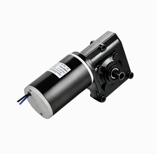
Performance Highlights: Output Speed and Torque: The motor offers a versatile range of speed and torque options, allowing for customization to suit specific application requirements. The gearbox provides precise control over speed and torque output. Efficiency: With its brushed DC technology and precision gearbox, this motor delivers high efficiency, minimizing energy consumption and heat generation. Reliability: The 7712Z motor is designed for continuous operation with minimal wear and tear, ensuring a reliable performance over an extended lifespan.
0 notes
Text
Top 3 Tips to Balance Performance & Power Consumption in Embedded Application Development
In embedded systems development, achieving the right balance between performance and power efficiency is an ongoing challenge—especially when working with microcontrollers (MCUs) and low-resource hardware. The right software design decisions can dramatically extend battery life without compromising responsiveness or reliability.

Here are three actionable strategies every embedded engineer should consider to get the best of both worlds.
1. Build Smarter Software with Efficient Code
The foundation of energy-efficient embedded development begins with how your software is structured and optimized.
Here’s what helps:
Choose better algorithms: Replacing inefficient logic (like O(n²)) with more optimized versions (O(n log n)) reduces CPU cycles and energy use.
Go event-driven, not polling: Event-based logic allows your system to enter sleep modes rather than constantly checking for changes.
Cut down on memory operations: Repetitive dynamic memory allocation increases power draw. Keep it lean and predictable.
Use hardware accelerators: Leverage MCU features like DSPs or crypto engines to offload work and reduce CPU load.
Pro Tip: Use compiler flags like -Os for size and power optimization. Tools like EnergyTrace or ARM's Power Debugger can help you find energy-heavy hotspots in your code.
2. Leverage OS and Middleware Power-Saving Features
Your choice of OS and middleware isn’t just a performance decision—it’s an energy one too.
Here’s how to optimize it:
Pick a power-aware RTOS: Systems like Zephyr and FreeRTOS come with built-in low-power features.
Use MCU low-power modes: Utilize deep sleep, stop, or standby modes to lower consumption during idle times.
Optimize peripheral management: Disable or scale down unused modules like timers, ADCs, or communication interfaces.
Reduce wake-up frequency: Combine tasks and delay non-critical activities to avoid excessive interruptions.
Scale clock speeds dynamically: Lowering clock rates during low workload periods helps reduce energy consumption.
Pro Tip: Use vendor-specific tools like the ST Power Calculator or Nordic’s Power Profiler to fine-tune system settings based on actual workloads.
3. Profile, Analyze, and Keep Optimizing
Even perfectly written code can consume more power than expected without proper testing and profiling.
Here’s your checklist:
Continuously monitor energy usage: Real-time power monitoring highlights inefficiencies across code paths.
Test in real-world conditions: Optimize based on typical usage patterns, not just lab simulations or edge cases.
Refine iteratively: Small updates—like fine-tuning interrupts or reducing wake-ups—can lead to major gains.
Slow down (intelligently): Your application doesn’t need to run at max speed—just fast enough. Slower = more efficient, when done wisely.
Pro Tip: Use simulation tools like Renesas e² Studio Power Profiler to preview energy impacts of code changes before testing on physical hardware.
Final Thoughts
In embedded development, managing the trade-off between performance and energy consumption is critical. But with the right software architecture, OS features, and continuous optimization, it's absolutely achievable.
By making informed engineering decisions, you can build high-performance, power-efficient embedded applications that last longer, run cooler, and deliver better user experiences.
👉 At Silicon Signals, we help companies build power-conscious embedded solutions using best-in-class design practices, real-time OS integration, and performance profiling techniques. 📩 Let’s connect to optimize your next embedded product — from prototype to production.
0 notes
Text
220 Ohm Resistor: Applications, Characteristics & Design Tips
In the world of electronics, resistors are among the most fundamental and widely used components. Among them, the 220 Ohm resistor holds a special place due to its versatility and ideal resistance value for many common applications. Whether you're just getting started with electronics or designing more advanced circuits, understanding the 220 Ohm resistor’s characteristics, typical applications, and best practices can help you design more reliable and efficient systems.

Characteristics of a 220 Ohm Resistor
A resistor with a value of 220 Ohms restricts the current in a circuit according to Ohm’s Law: V = IR, where V is voltage, I is current, and R is resistance.
For example, with a 5V supply, a 220 Ohm resistor will allow approximately 22.7 mA of current to pass through. This is a suitable current level for driving many LEDs or interfacing with logic-level components.
Key specs to consider:
Resistance: 220 Ohms (±1% for metal film, ±5% for carbon film)
Power rating: Commonly 1/4W, 1/2W, or 1W, depending on the use case
Tolerance: Defines how much the actual resistance can vary from the stated value
Common Applications
1. LED Current Limiting: The most frequent use of a 220 omega resistor is as a current-limiting resistor in LED circuits. LEDs typically require 10–30 mA of current. Using a 220 Ohm resistor helps prevent overcurrent that can burn out the LED, especially when powered by 5V sources like microcontrollers.
2. Microcontroller Interfaces: When interfacing LEDs or switches with microcontrollers (e.g., Arduino, Raspberry Pi, ESP32), 220 Ohm resistors are used to control current flow and protect I/O pins from excessive current draw.
3. Pull-down or Pull-up Resistors: While 220 Ohms is lower than typical pull-up/down resistor values, in high-speed or low-resistance applications, it can be used to ensure strong logic-level signals or to reduce signal noise.
4. Audio and Signal Circuits: In audio applications, 220 Ohm resistors can be used for impedance matching, signal attenuation, or current limiting in op-amp circuits.
Design Tips
1. Always Consider Power Rating: Use the formula P = I²R to ensure your resistor can handle the power it dissipates. For a 220 Ohm resistor carrying 25 mA, the power dissipated is about 0.14W—so a 1/4W resistor would be adequate, but higher wattage may be needed for safety or prolonged use.
2. Check Tolerance Based on Application: For precise analog circuits, opt for resistors with 1% or better tolerance. For general-purpose applications like LED limiting, 5% tolerance is usually acceptable.
3. Combine for Custom Values: Need a value close to but not exactly 220 Ohms? You can combine resistors in series or parallel. For example, two 110 Ohm resistors in series give 220 Ohms.
4. Mind the Temperature Coefficient: If your circuit operates in varying temperatures, choose resistors with low temperature coefficients to maintain stable resistance.
Conclusion
The 220 Ohm resistor is a simple yet indispensable tool in electronics. Whether you're lighting up an LED or protecting your microcontroller, understanding when and how to use it can elevate your circuit design. Keep it in your toolkit—it’s a small component with big impact.
ODG SNS:
Szxlxc: https://www.szxlxc.com
YouTube: https://www.youtube.com/@Origin_Data
Facebook: https://www.facebook.com/OriginDataGlobalLimited
Twitter: https://twitter.com/Origin_IC
Tiktok: https://www.tiktok.com/@origin_data
0 notes
Text
What are the main communication protocols in embedded systems?
Embedded systems rely on various communication protocols to enable efficient data transfer between components, microcontrollers, sensors, and external devices. These protocols can be broadly categorized into serial, parallel, wired, and wireless communication protocols.
UART (Universal Asynchronous Receiver-Transmitter) – A widely used serial communication protocol that facilitates full-duplex data exchange between embedded devices. It requires minimal hardware and is commonly used in debugging and low-speed data transfer applications.
SPI (Serial Peripheral Interface) – A high-speed, full-duplex protocol used for short-distance communication between a microcontroller and peripherals such as sensors, displays, and memory devices. It follows a master-slave architecture and is widely used in real-time embedded applications.
I2C (Inter-Integrated Circuit) – A multi-slave, half-duplex serial communication protocol designed for communication between multiple ICs using only two wires: SDA (data line) and SCL (clock line). It is highly efficient for low-speed applications and is commonly used in sensor integration.
CAN (Controller Area Network) – A robust, message-based protocol widely used in automotive and industrial applications. CAN allows multiple nodes to communicate efficiently without requiring a host computer. It ensures data integrity using error detection and correction mechanisms.
Ethernet – A widely adopted wired communication protocol that enables high-speed data transfer in embedded applications, especially in industrial automation and IoT systems. It supports networking capabilities for remote monitoring and control.
Bluetooth & Wi-Fi – These wireless protocols are essential for modern embedded systems, enabling connectivity in consumer electronics, IoT devices, and smart home applications. Bluetooth is preferred for short-range, low-power communication, while Wi-Fi offers high-speed data exchange over long distances.
Understanding these protocols is crucial for designing efficient embedded solutions. If you want to gain hands-on experience and expertise in these protocols, consider enrolling in an embedded system certification course.
0 notes