#Push button Arduino
Explore tagged Tumblr posts
Visit Tumblr Blog
Explore Tumblr blogs with no restrictions, modern design and the best experience.
Last Seen Tumblr Blogs


Fun Fact
Tumblr has been providing a Korean-language service since 2013.
Text
youtube
Push Button Multi LEDs Controller - Switch Case Vs Array Arduino Programming for Beginners Online Arduino Simulator Virtual Breadboard basic sketch examples: Programming and write Arduino UNO sketch with ezButton Arduino library for controlling LEDs toggle switch ON/OFF with a push button.
#programming#how to#simulator#wokwi#arduino#tutorials#Push Button#LEDs Controller#Virtual Breadboard#Youtube
0 notes
Text

The TTP224 is a 4-Channel Touch Sensor, meaning it has four touchpads. Whenever a capacitive load such as human hands is brought in proximity with the sense pad, the sensor then senses the change in capacitance and activates the switch. Custom sense-pads can be made from nearly any conductive material and these sensors can detect touch through thin layers of non-conductive materials such as glass, plastic, fabric or even wood. Each Touchpad has its respective output pin when the user touches a pad, the corresponding output pin will go high. It is very easy to interface with microcontrollers like Arduino to control different applications as a switch. It can be used in home automation, motor control, Relay control, etc. the module basically gets rid of the push button troubles.
6 notes
·
View notes
Text
My parents house has one of these! Not from home depot, my dad built it himself. He made it a few years ago and loves showing it off to people, which does defeat the purpose of a "secret" door, but it's pretty awesome and worthy of showing off.

This is what it looks like now, closed.

Here's what it looked like originally. The cats never really used the cat flap, so they didn't mind it being removed. And of course, for the cat tax, this is their cat Natasha (my replacement when I moved out; it's her job to cause chaos when I'm not there to do so myself and she's very good at it). Her eyes always look huge and almost cartoon-like. She thinks she's a human baby, and she KNOWS she's the favorite child in the family. Everyone loves her, even when she hisses at them.

Back on topic now.

This is the mechanism on the back of the door. I'm not really sure what the keypad is for, that might be part of something completely different, but the grey box with all the wires contains an Arduino that controls the electromagnetic latch. You can open it by asking Alexa "where does he keep the beer?" (his homebrewing equipment and the extra fridge are in that room). That option was added because he wanted a hands-free option for if he was carrying anything. There's a 3D printed bust of Albert Einstein on one of the shelves (I don't know why) which, if you lift its head back like a PEZ dispenser, reveals a Big Red Button that opens the door. The button is wireless, so you can take the statue(?) off the shelf. You can also pick up the rubber duck from a different shelf and hold it up to a specific (unmarked) spot on the back wall of the shelf and the magnet hidden in the duck will trigger a sensor in the wall. And finally, of course...

The candle. I think that square cut-out was filled in after this picture was taken, but you can see the sensor that opens the door when the (magnetic) candlestick is removed.
youtube
Unlike in the movie, this door just unlatches instead of fully rotating; you still need to push to open it. And finally, here's what it looks like open:

I think there may be one or two more things that can open it, but I'm not sure. He started with just the candle and then added on to it as he thought of new ideas. The picture above was taken before the duck and Einstein were added as they're not on the shelves. Probably a fake book with a secret lever will be next. It is a bit awkward to pull closed without a doorknob but that's a small price to pay for having a (not so) secret bookshelf door.

#hidden bookshelf doors!#at home depot now apparently! which is great!#everyone wants a hidden door like that but not everyone wants to build one#like my dad did
27K notes
·
View notes
Text
Esplora Arduino game controller

The ESPLORA Arduino game controller Board is an Arduino-compatible microcontroller board based on the Arduino Leonardo. Unlike previous models, it comes equipped with a variety of built-in sensors for immediate use in interactions.
This guide is perfect for individuals interested in using Arduino, but who don’t want to dive into electronics right away. To learn how to use the ESPLORA Arduino game controller Board in a simple and clear manner, be sure to read the Getting Started with Esplora guide.
The ESPLORA Arduino game controller Board boasts onboard sound and light outputs, as well as multiple input sensors such as a joystick, slider, temperature sensor, accelerometer, microphone, and light sensor. Additionally, it offers the option to enhance its functions through two Tinker-kit input and output connectors and a socket for a color TFT LCD screen.
Similar to the Leonardo board, the ESPLORA Arduino game controller Board also utilizes an Atmega32U4 AVR microcontroller with a 16 MHz crystal oscillator. It features a micro USB connection that can function as a USB client device, such as a mouse or keyboard. Additionally, there is a reset push button located in the upper left corner of the board for restarting purposes.
There exist four indicators, each displaying a different status.
The green indicator shows if the board is currently being powered.
The L [yellow] connects directly to pin 13 on the micro-controller for easy accessibility.
The [yellow] LED indicates data being transmitted or received through the USB connection.
Within the board lies all the necessary components to support the microcontroller. To begin, just connect it to a computer using a USB cable. The ESPLORA Arduino game controller Board is also equipped with built-in USB communication, allowing it to function as a mouse or keyboard when connected to a computer. It also offers a virtual serial/COM port (CDC). This alters the behavior of the board, which is further explained on our getting started page. On this page, you can find all the instructions for configuring your board and utilizing the Arduino Software (IDE) for coding and electronics experimentation.
The transfer of data, both in and out.
The ESPLORA Arduino game controller Board features a classic gamepad design, including an analog joystick on the left and four push buttons on the right. It also comes equipped with several onboard inputs and outputs:
The analog joystick features a center push-button and two axes, designated as X and Y. There is also a central pushbutton for added functionality.
Arranged in a diamond formation are 4 push-buttons.
The slider for the linear potentiometer is located towards the bottom of the board.
A tool to capture the volume (amplitude) of the surrounding environment.
A sensor that detects light to measure brightness.
The temperature sensor measures the surrounding temperature.
A three-axis accelerometer detects the orientation of the board with respect to gravity, along the X, Y, and Z axes.
The buzzer has the ability to generate square-wave tones.
The RGB LED features Red, Green, and Blue elements that allow for color mixing and a bright display.
The TinkerKit Inputs allow for easy connection between the sensor modules and 3-pin connectors.
The TinkerKit Outputs allow for easy connection of the TinkerKit actuator modules via the 3-pin connectors.
The TFT display connector can be used for a color LCD screen, SD card, or any other devices utilizing the SPI protocol.
To fully utilize all available sensors, the board employs an analog multiplexer. This way, multiple input channels (excluding the 3-axis accelerometer) can share a single analog input of the microcontroller. Selecting which channel to read is done through four additional pins on the microcontroller.
Communication is essential in any relationship, whether it be personal or professional. It plays a crucial role in maintaining strong connections and fostering understanding between individuals. Effective communication allows for open and honest dialogue, facilitating problem-solving and building trust. Without good communication, misunderstandings can occur, leading to conflicts and strained relationships. Therefore, it is important to prioritize effective communication in every aspect of our lives.
The ESPLORA Arduino game controller Board for the Leonardo offers various features for connecting with a computer, another Arduino, or different micro-controllers. The ATmega32U4 enables serial (CDC) communication through USB and is recognized as a virtual com port on the computer. It also functions as a full speed USB 2.0 device and can be used with standard USB COM drivers. A .inf file is needed for Windows.
The Arduino software comes equipped with a serial monitor for easy transmission of text data to and from the board. Whenever data is being sent via the USB connection to the computer, the RX and TX LEDs will light up on the board. Additionally, the ATmega32U4 has SPI capability accessible through the SPI library. In addition, the Esplora can act as a standard keyboard and mouse, allowing you to use programming to manage these input devices via the Keyboard and Mouse libraries.
The act of creating computer software, also known as programming, involves writing code using various languages and tools. This process requires a combination of problem-solving skills, critical thinking and creativity. Programmers must constantly learn new techniques and adapt to ever-changing technology in order to produce high-quality programs.
To start using the Esplora with your Arduino software (download), simply choose “Esplora” from the Tools > Board menu. For more information, refer to the getting started page. The ATmega32U4 on the Esplora comes pre-loaded with a boot-loader, enabling you to upload new code without an external hardware programmer.
The AVR109 protocol is the chosen method of communication. To avoid using the bootloader, you can program the microcontroller through the ICSP header. Additional instructions are available for reference.
A dedicated library for the Esplora simplifies writing sketches, with methods available for reading sensors and controlling onboard outputs. These high-level methods also perform pre-processing of data, such as converting temperature readings to degrees Fahrenheit or Celsius. Additionally, the library allows easy access to outputs like the RGB LED. For further information and examples, please refer to the Esplora library reference page.
The automatic reset and bootloader activation are key components in the software��s functioning.
Rather than relying on the physical reset button, the Esplora utilizes a software-based reset triggered by opening and then closing the virtual serial/COM port (CDC) at 1200 baud. This initiates a processor reset, temporarily cutting off the USB connection to the computer and causing the virtual port to disappear. The boot-loader remains active for approximately 8 seconds before it can also be activated by pressing the reset button on the Esplora.
Please be aware that upon initial power up, the board will launch the user sketch instead of the boot-loader, if available. Due to the specific reset process of the Esplora, it is most effective to allow the Arduino software to attempt a reset before uploading, especially if you typically press the reset button before uploading on other boards. However, in the event that the software is unable to reset the board, you can manually initiate the boot-loader by pressing the reset button on the board.
The USB port is equipped with overcurrent protection to prevent any potential damage.
The ESPLORA Arduino game controller Board comes equipped with a re-settable poly-fuse to safeguard your computer’s USB ports against shorts and over-current. While most computers have built-in protection, the fuse adds an additional level of security. In the case of a short or overload exceeding 500 mA, the fuse will disconnect the connection until the issue is resolved.
Regarding the appearance of this object, its external features will be discussed.
The ESPLORA Arduino game controller Board PCB has a maximum size of 6.5 inches in length and 2.4 inches in width. The USB and TinkerKit connectors extend beyond the width dimension. Additionally, there are four screw holes that allow for attachment to a surface or case.
1 note
·
View note
Text
2×4 Keypad 4×2 Keypad 8 Push Buttons V1.00 Key Board Matrix Keyboard Button for Arduino AVR PIC 24
http://i.securitythinkingcap.com/TClPdV
0 notes
Text
Arduino Plug and Make Kit: Richtungsanzeige mit Modulino Movement
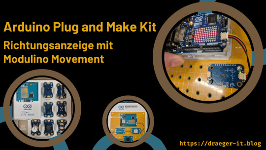
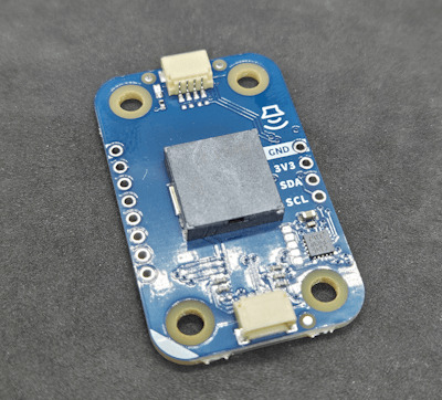
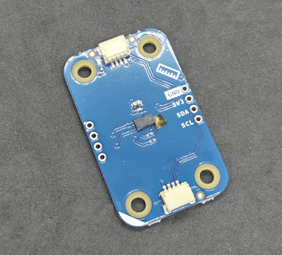
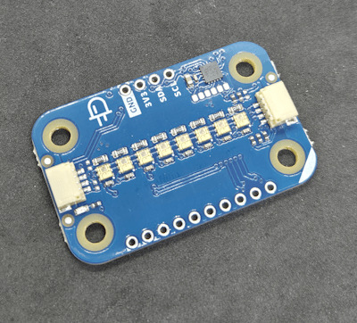
Das neue Arduino Plug and Make Kit habe ich dir bereits im passenden Beitrag vorgestellt, heute soll es um den Modulino Movement gehen, mit welchen man auf dem Arduino UNO R4 WiFi die Richtung anzeigen lassen kann. https://youtu.be/hbDoi3HJMIY Der Modulino Movement Sensor ist ein 6 Achsen Lagesensor vom Typ LSM6DSOXTR dieser verfügt über zwei Qwiic Schnittstellen, mit welche dieser direkt mit dem Mikrocontroller verbunden wird. Mit der zweiten Schnittstelle kannst du zusätzlich noch andere Sensoren / Aktoren anschließen. Die Sensoren / Aktoren werden via I2C angesprochen und verfügen somit jeweils über eine eindeutige Adresse.


Disclaimer: Ich habe das Arduino Plug and Make Kit für knapp 90 € (inklusive Versandkosten) selbst über den offiziellen Shop gekauft. Alle hier geäußerten Meinungen sind meine eigenen und wurden nicht von Arduino gesponsert oder beeinflusst.
Überblick über das Arduino Plug and Make Kit
Zum Lieferumfang des Arduino Plug and Make Kit gehört unteranderem die Sensoren / Aktoren: - Modulino Knob - ein Rotary Encoder mit Push Funktion, - Modulino Pixels - ein 8fach RGB LED Modul, - Modulino Distance - ein ToF Modul zum Messen von Entfernungen, - Modulino Movement - ein 6 Achsen Lagesensor, - Modulino Buzzer - ein Piezo Buzzer zum Erzeugen von Tönen, - Modulino Thermo - ein Sensor zum Messen von Temperatur & rel. Luftfeuchtigkeit, - Modulino Buttons - ein Modul mit 3 Taster
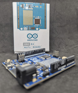
Arduino UNO R4 WiFi

3fach Taster Modul
Buzzer

Rotary Encoder
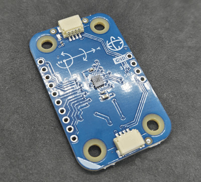
6 Achsen Sensor
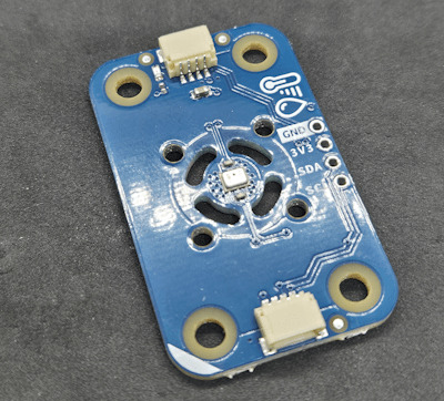
Temperatur & rel. Luftfeuchtigkeits Sensor
ToF - Distance Sensor
8fach LED Modul Und natürlich gehört noch der Arduino UNO R4 WiFi dazu, welcher über die benötigte Qwiic Schnittstelle verfügt.
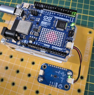
Aufbau der Schaltung - Arduino UNO R4 WiFi mit Modulino Movement Sensor
Die Schaltung ist recht schnell auf der Modulino Base aufgebaut, mithilfe der mitgelieferten Schrauben und Abstandshalter wird der Mikrocontroller an seinen Platz geschraubt und im unteren Bereich die Sensoren / Aktoren.

Arduino UNO R4 WiFi mit Modulino Movement Hier zeigt sich leider, dass die Kabel doch etwas kurz geraten sind. Wenn der Movement Sensor angeschraubt wird, sodass dieser parallel zum Mikrocontroller liegt, ist das Qwiic Kabel doch recht stramm.
Programmieren des Modulino Movement in der Arduino IDE
Auf der Seite https://courses.arduino.cc/plugandmake/lessons/modulino-movement/ findest du eine englische Dokumentation zum Modulino Movement mit einem Beispiel, welches ich dir nachfolgend einmal abgewandelt zeige. //Bibliothek für die Modulino Sensoren / Aktoren #include "Modulino.h" //erzeugen einer Objektinstanz vom Typ //Modulino Movement ModulinoMovement movement; void setup() { //beginn der seriellen Kommunikation mit 9600 baud Serial.begin(9600); //begin / Initialisierung der Kommunikation Modulino.begin(); //einrichten der I2C Verbindung zum Sensor movement.begin(); } void loop() { //aktualisieren der Daten vom Sensor movement.update(); //Ausgeben der Daten auf der seriellen Schnittstelle Serial.print("Lage: "); } Auf der seriellen Schnittstelle werden die Daten der Achsen X,Y & Z fortlaufend ausgegeben.

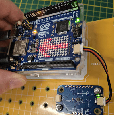
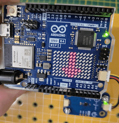
Anzeigen der Richtung mit der LED Matrix vom Arduino UNO R4 WiFi Der mitgelieferte Arduino UNO R4 WiFi verfügt über eine 8x12 LED Matrix (in rot) auf welcher wir recht simple Grafiken und auch Texte anzeigen lassen können. Mithilfe dieser Matrix möchte ich nun mit Pfeilen die Richtung anzeigen.
Programm: Anzeigen der Richtung des Modulino Movement an der LED-Matrix des Arduino UNO R4 WiFiHerunterladen #include "Modulino.h" #include "Arduino_LED_Matrix.h" #include "frames.h" ModulinoMovement movement; ArduinoLEDMatrix matrix; float x, y, z; float difference = 0.3; const int ROWS = 8; const int COLS = 12; const int PAUSE = 200; void setup() { Serial.begin(9600); Modulino.begin(); movement.begin(); matrix.begin(); } void loop() { movement.update(); x = movement.getX(); y = movement.getY(); z = movement.getZ(); if (abs(x) >= 0 && abs(x) = 0 && abs(y) = abs(y)) { if (x > 0) { matrix.renderBitmap(pfeilRechts, ROWS, COLS); } else { matrix.renderBitmap(pfeilLinks, ROWS, COLS); } } else if (abs(y) >= abs(x)) { if (y > 0) { matrix.renderBitmap(pfeilVorne, ROWS, COLS); } else { matrix.renderBitmap(pfeilHinten, ROWS, COLS); } } delay(PAUSE); } Read the full article
0 notes
Text
CMPE453 Section-2 Lab-6 ADJUSTABLE CLOCK DESIGN BY USING TIMERS solved
In this lab students will design a real clock by programming Timer1 of AVR Microcontroller. Hardware Requirements 1) Arduino Uno Board 2) Arduino Base Shield 3) Breadboard 4) Push Button 5) LCD Display 6) 2 Leds with Resistors 7) Connecting wires Software Setup In the software you are required to do the following. 1. It should continue displaying the current time on LCD display in the form of…
0 notes
Text
CMPE453, Section-2 Lab-6 ADJUSTABLE CLOCK DESIGN BY USING TIMERS
In this lab students will design a real clock by programming Timer1 of AVR Microcontroller. Hardware Requirements 1) Arduino Uno Board 2) Arduino Base Shield 3) Breadboard 4) Push Button 5) LCD Display 6) 2 Leds with Resistors 7) Connecting wires Software Setup In the software you are required to do the following. 1. It should continue displaying the current time on LCD display in the form of…
0 notes
Text
Electric ... Dice ... Machine (Makerspaces week 4)
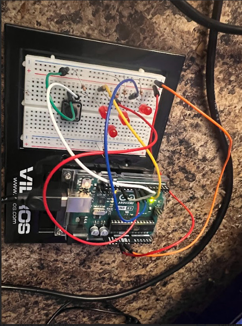
This week our challenge was to use our Arduino boards to create a circuit that represented a randomized dice roll. By successfully creating a circuit that connects resistors, different size resistors, and a push button we hope to resemble a dice rolling at random, generating different values ranging from 1-6.
Lets "dice" into this

Phase 1: Initially the idea was to construct and effectively run the circuit for a push button. I began by setting up a build with the 7 LEDs but I did not leave enough room for the individual resistors. The push button needed a resistor as well along with additional wiring. There was no room so I scrapped it and started again. After rebuilding the circuit I assigned my push button to input 2. Realizing the connection of the LED's was more important than the location I felt as though this would be a successful build. This build was good, please see attachments below for this phase of this weeks challenges:
Code: const int buttonPin = 13; const int ledPin = 9; int currentState; int lastState = HIGH; int ledState = LOW; void setup() { Serial.begin(9600); pinMode(ledPin, OUTPUT); pinMode(buttonPin, INPUT); } void loop() { currentState = digitalRead(buttonPin); if (lastState == HIGH && currentState == LOW) { ledState = !ledState; digitalWrite(ledPin, ledState); } lastState = currentState; delay(50); }
I felt good at the end of this phase of week 4's activities. After a positive phase 1 I was ready to begin phase 2.
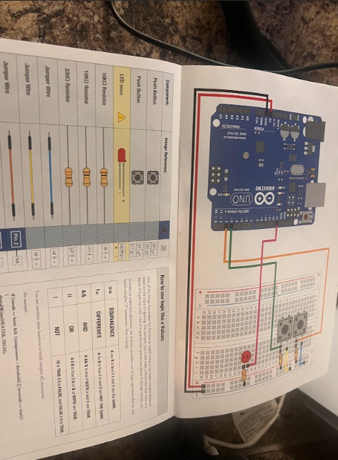
Phase 2: In the next phase my goal was to connect all 6 LED bulbs and get the circuit read the randomized roll results. After placing all 6 LED's onto the board and verifying their connection I went and altered the code to include the dice and random order. After locating a code and getting it wrote to fit my circuit it was time for me to test my circuit.
See results in video below:
There was a resistor that had fallen out of place, after correcting this resistor and realizing that one LED was facing the opposite way this was the next test
See results in video below:
Code: #define BUTTON_PIN A0 const byte die1Pins[] = {3, 4, 5, 6, 7, 8,9}; void setup() { pinMode(A0, INPUT_PULLUP); for (byte i = 0; i < 7; i++) { pinMode(die1Pins[i], OUTPUT); } } void displayNumber(const byte pins[], byte number) { digitalWrite(pins[0], number > 1 ? HIGH : LOW); // top-left digitalWrite(pins[1], number > 3 ? HIGH : LOW); // top-right digitalWrite(pins[2], number == 6 ? HIGH : LOW); // middle-left digitalWrite(pins[3], number % 2 == 1 ? HIGH : LOW); // center digitalWrite(pins[4], number == 6 ? HIGH : LOW); // middle-right digitalWrite(pins[5], number > 3 ? HIGH : LOW); // bottom-left digitalWrite(pins[6], number > 1 ? HIGH : LOW); // bottom-right } bool randomReady = false; void loop() { bool buttonPressed = digitalRead(BUTTON_PIN) == LOW; if (!randomReady && buttonPressed) { /* Initialize the random number generator with the number of microseconds between program start and the first button press */ randomSeed(micros()); randomReady = true; } if (buttonPressed) { for (byte i = 0; i < 10; i++) { int num1 = random(1, 7); displayNumber(die1Pins, num1); delay(50 + i * 20); } } }
Reflection: This week was challenging much like each week up to this point. I enjoyed being able to create something as cool as an electric dice machine, completing a circuit of this level of difficulty only makes me wonder what is ahead.

0 notes
Text
youtube
Push button Short press long press led controller basic io arduino uno programming tutorial for beginners
0 notes
Text
This Arduino Uno Proto Shied comes with a mini breadboard is used to design the Arduino uno based prototype circuits faster and in a managed way. You can solder parts to the prototyping board or can use the attached breadboard to quickly test circuit ideas without soldering.
Features:
Comes with two power rails in the middle and sides.
Standard 0.1″x0.1″ prototyping board with big pads
Two integrated red and green LEDs
A reset button with one additional general purpose push button.
Have an IC pattern for adding DIP ICs up to 20 pins
Have a surface-mount chip area for up to 14 SOIC
2 notes
·
View notes
Text
TTP224 4 Channel Digital Touch Sensor For Arduino
The TTP224 is an integrated circuit (IC) that functions as a touch pad detector, providing 4 touch keys. It is specifically designed to replace conventional direct button keys with various pad sizes. By utilizing capacitive touch technology, this IC enables electronic devices to detect when a finger is in close proximity to the surface, simulating the action of pressing a button, similar to how a physical push button operates.
0 notes
Text
How to Switch On-Off LED Using Push button in Arduino?
How to Switch On-Off LED Using Push button in Arduino?
The Push button is a component that connects two points in a circuit when you press it. The example lights an LED when you press the button. We connect three wires to the Arduino board. The first goes from one leg of the pushbutton through a pull-up resistor to the 5 volt supply. The second goes from the corresponding leg of the pushbutton to the ground. The third connects to a digital i/o pin…

View On WordPress
0 notes
Text
youtube
This is an amazing video, and this channel has lots of information on different types of mechanisms in action. Physics might seem kind of boring until you stop thinking about it as math and start thinking about it like machines and actions, such as, "I pull a lever which turns a disc that opens the door to my jewelry box", or "I push a button that lets me adjust the time on my litterbox last cleaned counter." (the latter of which I'm actually playing around with, and if I'm successful will post here!) if you can build a practical solution, it'll work despite having electricity or not. and if it's a simple machine, like pulleys, levers, pins, etc. then you can build it out of pretty much anything. Plus you can augment stuff with things like an arduino to help manage more complex functions which adds so much more to whatever you're making! In a time where stuff breaks down a lot, learning about the mechanics of things can not only help you repair things but help you make more efficient items that aren't subject to stuff like planned obsolescence.
#simple machines#physics#educational content#videos#education#geneva drives#machinery#mechanics#Youtube
3 notes
·
View notes
Text
Project 16 - The Matrix
And here we are! The final project for this semester. I bought some 8x8 dot matrix displays and went wild with it.
I had a couple different ideas with this project. First I wanted to make something that would display the temperature, but the temperature sensor I had wouldn’t give me an accurate reading, so I moved onto my backup plan: A LED Availability Sign! Let people know if you’re free to chat or occupied with work with the push of a button!
This sign can display 3 different languages, English, Spanish, and German. I was going to include French in this, but the characters with accent marks wouldn’t display right. Oh well.
Building materials:
• 4 8X8 displays (I used these ones from Amazon)
• 220 Ohm resistors
• Push Buttons
• LOTS of female-female wires
Board:

I'd include a picture of how I wired up the matrixes, but I'll link you to the tutorial i followed instead. They did a really good job and can explain how to hook things up way better than I ever could.
Video:
youtube
Sorry about the matrixes not lining up quite right, it was hard to get them to stay in place without permanently affixing it to something.
And finally the code. I build my code off of the demo found in the link above.
Thats everything for this class completed! Thanks for following along with my Arduino adventure : )
3 notes
·
View notes
Text
Arduino-Experiment: LED-Steuerung mit einem Quecksilberschalter

In diesem Beitrag werde ich gemeinsam mit dir in die faszinierende Welt der Elektronik eintauchen und ein aufregendes Experiment mit dem Arduino Quecksilberschalter durchführen. Wir werden herausfinden, wie wir diesen innovativen Schalter nutzen können, um die Leuchtkraft einer LED zu steuern. Also lass uns eintauchen und entdecken, wie wir durch die Kombination von Technologie und Kreativität eine spannende Möglichkeit haben, eine LED-Lichtquelle auf einzigartige Weise zu kontrollieren.

Vorsicht beim Umgang mit Quecksilber
Beim Umgang mit Quecksilber ist Vorsicht geboten: Trage Schutzausrüstung, arbeite in belüfteten Räumen, vermeide Kontakt mit Haut und anderen Metallen, und entsorge es sicher. Quecksilber verdampft bei Raumtemperatur, daher auf Dichtigkeit achten. Bei Bruch sofort lüften, aufsammeln und Gerät reinigen. Schulung vorab ist wichtig für sicheres Experimentieren. Da bei diesem Modul die Quecksilberkugel einem Glasröhrchen ist, ist dieses flüssige Metall in der Regel und bei ordentlichem Gebrauch sicher.
Aufbau des Quecksilberschalters
Der Quecksilberschalter ist recht einfach aufgebaut. Es ist wie erwähnt eine kleine, flüssige Kugel in einem Glasröhrchen, welches zwei Kontakte schließt oder öffnet (je nach Lage).

Quecksilberschalter - KY-017 für Arduino, Raspberry Pi Für den Anschluss an den Mikrocontroller steht eine 3-polige Stiftleiste mit den Beschriftungen "-", "S" wobei die Mitte nicht beschriftet ist, hier jedoch als "VCC" / "+" dient.
Bezug eines Quecksilberschalters für den Arduino
Das in diesem Beitrag verwendete Modul findest du auf ebay.de und aliexpress.com zu recht günstigen Preisen. Seit dem Jahr 2020 ist die Herstellung und der Verkauf von Produkten, die Quecksilber enthalten, wie spezielle Leuchtmittel, Thermometer, Pestizide und Biozide, nicht mehr erlaubt. Daher kann ich dir hier keinen Link anbieten ohne das ich mich ggf. Haftbar mache.
Aufbau einer Schaltung mit einer LED
Kommen wir nun zu einer kleinen Schaltung, um diesen Quecksilberschalter zu testen. Die wohl einfachste Schaltung mit diesem ist mit einer LED. Über diese LED können wir den Ladezustand der Quecksilberkugel visualisieren.


Der Arduino Nano ESP32 ist vom Pinout mit dem Vorgängermodell Nano V3 gleich und daher kannst du für diese Schaltung den alten auch verwenden.
Programmierung des Quecksilberschalters am Arduino Nano ESP32
Der Code ist eigentlich recht einfach, denn wir nutzen den Quecksilberschalter wie einen Taster. //LED am digitalen Pin D2 angeschlossen #define led 2 //Quecksilberschalter am //digitalen Pin D3 angeschlossen #define button 3 void setup() { //Pin der LED als Ausgang definiert pinMode(led, OUTPUT); //Pin des Quecksilberschalters //als Eingang definiert pinMode(button, INPUT); } void loop() { //auslesen des Zustandes des //Quecksilberschalters int state = digitalRead(button); //zuweisen des Zustandes zur LED //Wenn der Status 0 ist dann soll //die LED leuchten, andernfalls //soll diese nicht leuchten. digitalWrite(led, state == 0 ? HIGH : LOW); } Wie zu erwarten bewirkt das Programm, dass, wenn die Quecksilberkugel den Kontakt schließt, die LED aufleuchtet.
Fazit & Ausblick
Abschließend lässt sich festhalten, dass der Quecksilberschalter vom Typ KY-017 eine einfache, aber vielseitige Komponente ist, die auf Lageänderungen reagiert und somit genutzt werden kann, um Objekte zu sichern. Dieses Konzept bietet Raum für kreative Anwendungen. Im kommenden Beitrag werde ich dir zeigen, wie du mithilfe einer alternativen Methode - einer kleinen Metallkugel - eine Push-Benachrichtigung bei Lageänderungen realisieren kannst. Auch wenn der Quecksilberschalter nicht mehr zum Einsatz kommt, erzielen wir dennoch das gleiche Ergebnis. Bleib gespannt auf die spannende Fortsetzung! Read the full article
0 notes