#Relay Board for Raspberry Pi
Explore tagged Tumblr posts
Visit Tumblr Blog
Explore Tumblr blogs with no restrictions, modern design and the best experience.
Last Seen Tumblr Blogs


Fun Fact
Total funding amounts to $125.3M.
Text
This 16 Channel Relay Module consists of sixteen 5V relays and each one of the individual relay needs 15-20mA driver current. This module has a light coupling protection (optocoupler) which provide opto-isolation for safety purposes. This is a Relay module of 16 channel interface board that can be control various appliances, and other electronic equipment with large current. It can be controlled by Micro-controllers like Arduino, Raspberry-pi, ARM, TTL logic directly.
3 notes
·
View notes
Text
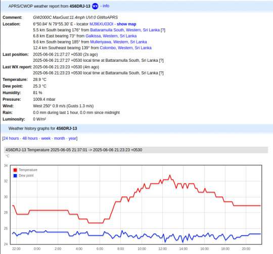
Ecowitt weather station to APRS bridge
Ecowitt2APRS is a new open-source Linux service that I have been working on for the past few weeks. This project is designed to seamlessly integrate weather data from Ecowitt compatible professional weather stations into the global Automatic Packet Reporting System Internet Service (APRS-IS) network, transmitting this information in the standardized format of APRS weather packets.
APRS, an amateur radio-based system, facilitates real-time tactical digital communications, covering applications such as GPS position reporting and the dissemination of meteorological data. Ecowitt2APRS addresses a specific need within this ecosystem: providing a lightweight and efficient method for weather stations to contribute to this data stream.
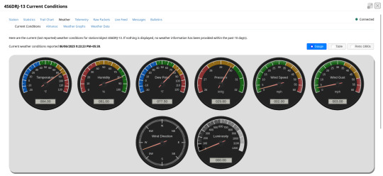
The Ecowitt2APRS service is developed as a minimalist daemon for Linux environments. It ingests live weather data from Ecowitt compatible stations, converts it into the required APRS weather packet format, and then relays these packets to the APRS-IS network. One of my primary objectives was to create a service that operates effectively on minimal Linux systems, such as low-power SBCs like the Raspberry Pi Zero. This enables dedicated, continuous weather reporting with minimal operational overhead and power consumption.
I'm testing this system with my Ecowitt WiFi weather hub - GW2000C. The live feed from my Ecowitt2APRS instance is available as 4S6DRJ-13, and I am hosting the Ecowitt2APRS daemon on the Orange Pi Zero LTS board.
As an open-source initiative, all source code, documentation, and installation instructions are publicly available in the project repository on GitHub. This page also provides pre-built binaries of Ecowitt2APRS for ARM64, ARMv7, and AMD64 architectures. Anyone interested in deploying this can download the binaries or compile the source code themselves. The source code has limited external dependencies and can be easily built using the GCC toolchain. The compilation steps are outlined in the project's readme file.
To manually deploy the downloaded package, follow these steps:
1. Extract the files:
tar -xvf ./ec-aprs-wx-linux-<PLATFORM>.tar.gz
2. Copy the necessary files:
sudo cp ./ec-aprs-wx /usr/local/bin/ec-aprs-wx sudo cp ./config.cfg /etc/ec-aprs-wx.cfg sudo cp ./ec-aprs-wx.service /etc/systemd/system/ec-aprs-wx.service
Before starting the service, make sure to open the /etc/ec-aprs-wx.cfg file and edit the fields: APRS_CALLSIGN_SSID, APRS_PASSCODE, APRS_LATITUDE, and APRS_LONGITUDE. The details for these fields are covered in the readme file of the project.
To start the service, issue the following command:
sudo systemctl daemon-reload
To enable the service to start automatically on system reboot, issue the following command:
sudo systemctl enable ec-aprs-wx.service
To trigger this service, the Ecowitt device needs to be configured, with the configuration steps detailed in the project's readme file.
If all configuration steps are correct, you should be able to observe the weather data feed from APRS monitoring sites like https://aprs.fi or https://aprs.to.
0 notes
Text
5V Single Channel Relay Module: A Detailed Guide
The 5V Single Channel Relay Module is a powerful and compact device that serves as a bridge between low-power circuits and high-power devices. It is commonly used in projects requiring electrical isolation or automation, making it popular among hobbyists and engineers alike. In this guide, we will explore its functions, applications, wiring, and much more to give you a full understanding of this versatile module.
What is a 5V Single Channel Relay Module?
A 5V Single Channel Relay Module is an electronic switching device designed to control high-voltage electrical devices using a low-power input. The term "5V" refers to the operating voltage required to activate the relay, while "single channel" means it can control one device or circuit at a time.
The module is widely used in home automation, robotics, and various DIY projects. Its ability to switch between circuits without a direct electrical connection makes it a safer choice for controlling high-voltage appliances.
How Does a 5V Single Channel Relay Module Work?
The relay module operates as an electromechanical switch. It uses a small input voltage to energize an internal coil, creating a magnetic field. This magnetic field moves a lever inside the relay to either open or close a circuit. By doing so, it allows or interrupts the flow of current to the connected device.
The module typically has three main connections:
Input Pins: For connecting the control signal.
Common Pin (COM): The shared connection between the relay and the device.
Normally Open (NO) and Normally Closed (NC): These determine the state of the circuit (open or closed) when the relay is activated or deactivated.
Features of a 5V Single Channel Relay Module
Low Power Requirement: Operates on just 5V input.
Isolation: Electrical isolation ensures safety between low-voltage control circuits and high-voltage devices.
LED Indicators: Built-in LEDs indicate the relay’s state, making it easy to troubleshoot.
Compact Design: Small and lightweight, suitable for various projects.
Applications of the 5V Single Channel Relay Module
The 5V Single Channel Relay Module has countless uses in modern electronics, such as:
Home Automation: Control appliances like lights, fans, or water pumps using microcontrollers or development boards like Arduino or Raspberry Pi.
Robotics: Enable remote or automated control of motors and actuators.
Industrial Automation: Automate machinery and monitor processes.
Smart IoT Systems: Integrate with IoT platforms to create smart, connected systems.
How to Wire a 5V Single Channel Relay Module
Connecting a 5V Single Channel Relay Module to a microcontroller is straightforward. Follow these steps for basic wiring:
Power the Module: Connect the VCC pin to the 5V output of your microcontroller or external power supply.
Connect the Ground: Link the GND pin of the relay to the ground pin of your controller.
Signal Pin: Attach the IN pin to the microcontroller's GPIO pin that will control the relay.
Device Connection: Wire the high-voltage device to the NO, NC, and COM pins based on your requirements.
Always ensure proper insulation and avoid direct contact with live wires during setup.
Benefits of Using a 5V Single Channel Relay Module
Safety: Provides electrical isolation, protecting the low-power circuit.
Versatility: Works with a range of devices and voltages.
Reliability: Durable and can withstand frequent switching operations.
How to Test a 5V Single Channel Relay Module
To test the module, follow these simple steps:
Power Up the Relay: Connect the module to a 5V power source.
Apply Control Signal: Send a HIGH or LOW signal to the input pin.
Listen for a Click: A clicking sound indicates the relay is switching states.
Check the LED Indicator: Ensure the LED lights up when activated.
Testing ensures the module functions as intended before integrating it into your project.
Choosing the Right Relay Module
When selecting a relay module, consider the following factors:
Operating Voltage: Ensure compatibility with your controller.
Load Capacity: Check the maximum current and voltage the relay can handle.
Channels: Choose a module with an appropriate number of channels based on your needs.
Integrating the 5V Single Channel Relay Module with Arduino
One of the most popular applications of this module is in Arduino projects. Here’s a simple example:
Components Required
Arduino Board
5V Single Channel Relay Module
Jumper Wires
Load (e.g., a light bulb)
Steps
Connect the relay module's VCC and GND to the Arduino’s 5V and GND pins.
Attach the IN pin to a digital GPIO pin (e.g., pin 7).
Write a program to toggle the relay using Arduino’s digitalWrite function.
Upload the code and observe the relay switching the connected load.
Maintenance and Troubleshooting
Regular maintenance can extend the lifespan of your 5V Single Channel Relay Module. Check for the following:
Loose Connections: Ensure all wires are securely connected.
Dust and Debris: Clean the module periodically to prevent short circuits.
Wear and Tear: Inspect for physical damage or corrosion.
If the module fails to function, verify the power supply and input signals. Replace damaged modules promptly to avoid system downtime.
0 notes
Text
Relay Module for Raspberry Pi | 4 Channel 3V Relay Board for Raspberry Pi
Raspberry pi 4 Channel 3V Relay Board
4 channel relay shield with 2A 120 Volts AC output and 2A 24 Volts DC output ratings. 4 High-quality 3V Relays that loads up to 2A/24VDC or 2A/120VAC. Compatible with all models of the Raspberry Pi such as Raspberry Pi 4, 3, 2, Zero and Zero W. @raspberrypigk @raspberrypi-piface @electronics-geek
#Raspberry pi#Relay Module#Relay Board#Relay Board for Raspberry Pi#4 channel relay board#3v Relay Board for Raspberry Pi
0 notes
Text
.
#been watching videos of a guy diy some things into smart devices via custom circuit board and wiring different relays#not only that he makes them wifi and even cloud accessible via connecting a different motherboards#shit is legit so cool#he made an automated power outlet that can turn itself off or on the grid via his phone or wifi#literally then he made door sensors using some magnets and some casings with his 3d printer to house them#which would be used as an indicator of when the door is closed or open#also by using raspberry pi he was also able to make it work via cloud remotely and through WiFi#the coding process was straight forward since the main board was compatible with the software he uses so he just copied paste the code#it was so simple it got me thinking my dumb ass can actually do this lol#i long to be computer engineer and make my own custom built technology 🤣
2 notes
·
View notes
Text
Stupid thought
R1 Lack 3d printing enclosure has
- the 16A switch from the back of the printer (to control ac to the power supply)
- three 10A switches (DC to printer logic board, lights, air filter)
There at least WAS an octoprint plugin, Octorelay, that was built around software control of such things, given proper supporting hardware
But I'd still want my switches
Which, by my research, would mean 4 momentary switches, and 4 locking relays.. which require at least 2 normal relays each. And more electronics then I'm comfortable with at the moment. And that doesn't cover an off-only signal from the control computer... gpio via USB, maybe.
OR. Or. I could wire everything up to a raspberry pi pico. The 4 momentary switches, 4 standard relays. 30A ones, even if the 10A components have been fine so far. Program the pico to respond to both switches and act as the proper type of usb device to send my gpio signals. Hmm.
2 notes
·
View notes
Text
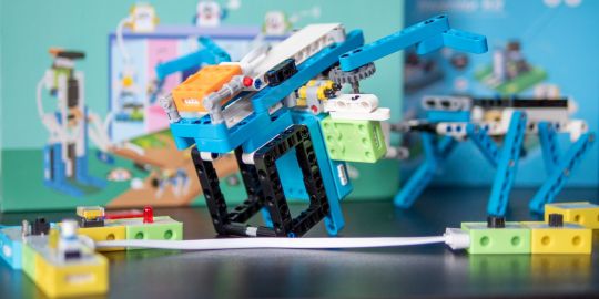
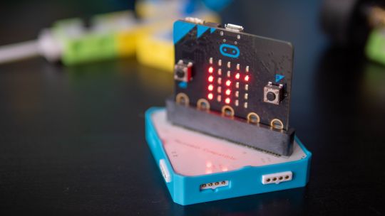
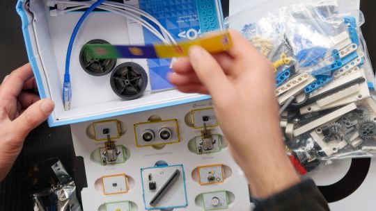
Elecrow Crowbits: The Ultimate LEGO-Compatible STEM Learning System That Grows With Your Child
Elecrow Crowbits
9.00 / 10
Read Reviews
Read More Reviews
Read More Reviews
Read More Reviews
Read More Reviews
Read More Reviews
Read More Reviews
Read More Reviews
Read More Reviews
Read More Reviews
Read More Reviews
Read More Reviews
Read More Reviews
Read More Reviews
Read More Reviews
Read More Reviews
Read More Reviews
Read More Reviews


Shop Now
Brick builds, combined with magnetic electronics blocks, and programmable micro-controllers. Does it get any better than this? I think my long search for the perfect STEM learning kit is complete. If you have young children just coming up to the right age for it, the Crowbits system can accompany them throughout their primary education and beyond.
Key Features
Magnetic blocks build circuits
Kits to suit various levels
Specifications
Brand: Elecrow
Development Platform: Scratch and MicroPython
Pros
LEGO-compatible to customize your builds
Full range of components planned
Level up with your child with more complex projects and programmable microcontroller
Familiar Scratch-based programming software
Cons
It's a Kickstarter
Instructions need work expanding on the principles and explanations
Buy This Product
Elecrow Crowbits other
Shop
// Bottom var galleryThumbs1 = new Swiper('.gallery-thumbs-1', { spaceBetween: 10, slidesPerView: 10, freeMode: true, watchSlidesVisibility: true, watchSlidesProgress: true, centerInsufficientSlides: true, allowTouchMove: false, preventClicks: false, breakpoints: { 1024: { slidesPerView: 6, } }, }); // Top var galleryTop1 = new Swiper('.gallery-top-1', { spaceBetween: 10, allowTouchMove: false, loop: true, preventClicks: false, breakpoints: { 1024: { allowTouchMove: true, } }, navigation: { nextEl: '.swiper-button-next', prevEl: '.swiper-button-prev', }, thumbs: { swiper: galleryThumbs1 } });
Take a moment to imagine the perfect electronics and engineering learning kit. It would be so simple even a child could use it: magnetic blocks, perhaps? Modular, so you could swap bits in and out to modify projects. It would scale up, so you could start with simple circuits and move on to programmable hardware, catering to all levels of the curriculum. Lastly, I'd throw in LEGO-compatible, because LEGO bricks are the best tool for creativity and engineering ever made.
That's exactly everything the Elecrow Crowbits system is, and it's crowdfunding now.
youtube
Disclaimer: This is a Kickstarter
Four of the five available Crowbits kits were sent to us for evaluation during the Kickstarter, however, they are still very much in the prototype stage, and we've evaluated them on that basis. Some bits were missing, some were non-functional, and the software is still a work-in-progress. This is to be expected at this stage, but the core system is solid.
Also, the usual Kickstarter caveat applies: your money is at risk, and there's no legal obligation with any crowdfunding campaign to actually deliver a product. That said, this isn't Elecrow's first campaign (the CrowPi 1 and CrowPi 2 were a huge success). It's a well-established company with a reputation to maintain and a good track record, so we think the risk is minimal.
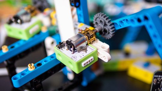
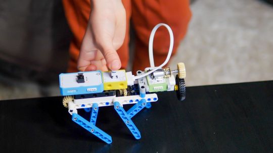
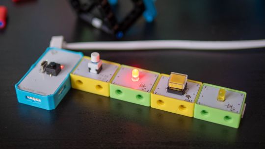
What Are Crowbits?
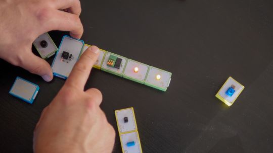
Crowbits modules are magnetic electronics blocks with LEGO-compatible pin holes on the side and stud holes underneath. The 4-pin pogo connections are either male or female, and have a small protrusion on the bottom to prevent wiring them the wrong way around.
Extension cables enable you to place a module elsewhere, and these too feature the same magnetic connection and can't be plugged in the wrong way. The whole system operates on a safe, low voltage, and with rechargeable battery blocks that charge over micro-USB.
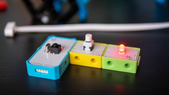
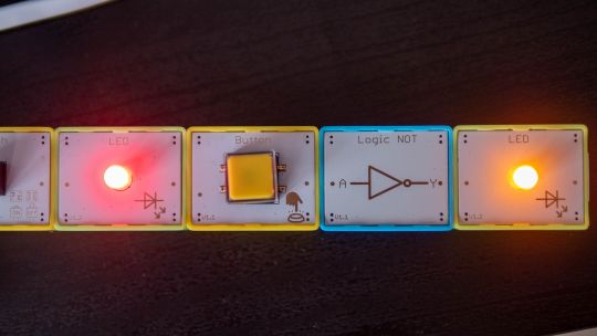
Each Microbits module is color-coded for ease of understanding:
Blue modules are power and logic. In the basic sets, these are simple battery modules that don't require programming. In more advanced sets, these are programmable microcontrollers with pin numbers on the connections for addressing modules directly.
Yellow modules are inputs: buttons, basics sensors and such.
Green modules are outputs: LEDs, motors, buzzers, relays.
Orange modules are special and require serial communication lines to the programmable hub. These include things like color sensors, joysticks, or 2G communications hub.
A large range of Crowbits modules are planned, though these will be available separately at a later date. For now, you can only purchase the full Crowbits kits with their included module selections.
No Programming Required!
Since the first two Crowbit kits require no programming, how does that work? Simple, as long as you follow some basic rules:
Yellow input modules must be placed on the left of green output modules (when viewed with the module name being on the top, and symbol in the bottom right).
One input module can control a chain of output modules.
A new input-output chain will be created if you add another input module to the right.
Blue battery modules can go anywhere in the circuit, and their orientation doesn't matter as long as the pins are compatible.
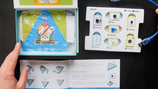
With this, kids can create basic circuits. For more complex circuits (that still don't need programming), a series of bitwise logic operator modules are planned. A "NOT" logic gate is included in the Hello kit, and more will be available later.
This enables you to reverse an input, such that a button that would normally turn on an LED, would now function as a button to turn the LED off.
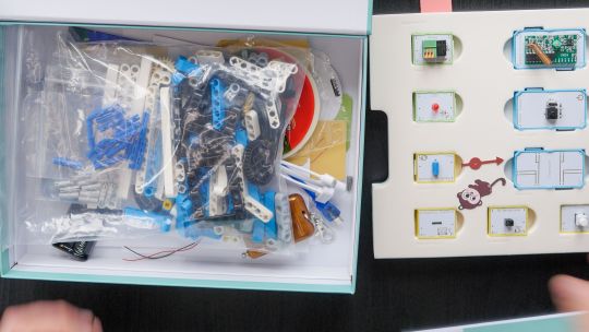
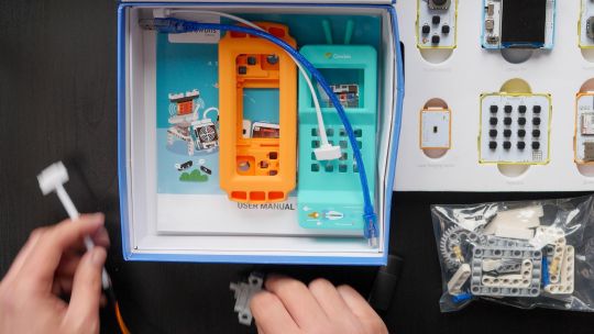
Crowbits Kits
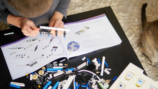
The Crowbits Kits are divided into five stages of increasing complexity, but all share a common system and are compatible with each other. Some modules are duplicated between kits. Let's take a look at the contents and direction of each kit.
Hello Kit
The most basic of kits is also the cheapest, available for $30. It includes seven modules, one of which is a small battery module. Five project builds are included along with pre-cut cardboard parts to stick together. No programming is required, and the Hello kit is suitable for ages 5-6.
Explorer Kit
The Explorer Kit continues the no-programming theme, but adds movement through the use of a motor module and pack of technic pieces for some basic engineering. A total of eight modules are included, one of which is a medium-sized battery pack. The build guide contains a mix of brick-based and cardboard projects. With a little adult supervision on the trickier mechanical elements, 7-8-year-olds should be able to handle this kit. The Kickstarter price is $80, rising to $130 RRP.
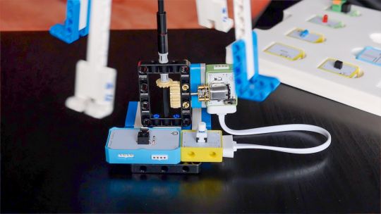
Inventor Kit
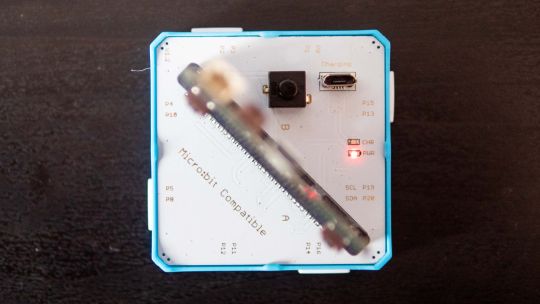
The Inventor Kit is a big step up that introduces programming concepts and more complex mechanical engineering. The main module of this kit requires a BBC Micro:bit (v1) to function. This is not included, though it may be available as an add-on if you don't already own one.
For those not familiar, the BBC Micro:bit is an all-in-one programmable microcontroller specifically designed for use in the school curriculum. It's widely used in UK schools, and gaining ground in the US.
Related: 10 Beginner Projects for the BBC Micro:bit
Ten modules are included as well as a large pack of technic bricks, suitable for building projects such as an obstacle avoidance car or color-sorting robot.
Given the use of BBC Micro:bit and Scratch programming in schools from around age 8, this kit would be suitable for 8-12 year-olds. It's available during the Kickstarter for $90, RRP $130.
Creator Kit
This was not yet ready for review at the time of writing, but the core of the Creator kit is an Arduino-based board, and includes 11 modules more suited to smart home projects and more complex interaction programming, along with a small selection of technic blocks. There are no movement motors. The Creator kit is available for $100 now, or RRP $150 later.
Master Kit
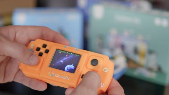
The most advanced kit in the range, the Master Kit uses an ESP32-based board at its core, featuring a TFT color screen. Also in the kit are some joystick modules, a small keyboard, laser ranging sensor, and 2G connection.
The Master Kit has a small number of technic bricks, and as well two silicone cases for a working phone, and a retro game console. It's designed to show the modules coming together to create a finished product. However, programming the firmware is quite complex, so I'd rate this kit as suitable for 14 and up. The early pricing is $100 for the Master kit, rising to $150 RRP.
LEGO-Compatible, not Actual LEGO
I should note that the Crowbits kits are not an officially endorsed nor licensed LEGO group product, and do not contain actual LEGO bricks. Instead, the LEGO-compatible technical bricks carry the brand name "CaDA", which I've not come across before.
That said, the bricks are well made and connect simply and securely, which is always a worry with off-brand construction bricks. For context, you can buy a set of at least 500 CaDA technic bricks on AliExpress for under $30.
You can of course decorate the builds with your own real LEGO, should you wish.
As a nerdy side-note, be warned that the instruction for the brick builds are read left-to-right, rather than top-to-bottom. If you're a LEGO family, this is mildly infuriating and means your child might skip steps!
Programming with LetsCode
Programming your Crowbits kits is done using Elecrow's new LetsCode (currently only for Windows, but support is promised for Mac OS and Raspberry Pi later).
LetsCode is a customized version of Microsoft MakeCode, which is itself based on the graphical block programming language, Scratch 3.0. As such, it'll be immediately familiar to anyone with experience of Scratch programming. It's widely used for introductory programming classes all over the world, and includes graphics blocks for all common concepts like loops, branching, and functions.
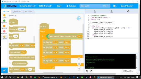
Pin numbers are printed directly on the blue modules, so it's easy to see which component is attached where.
If you outgrow graphical programming, you will also be able to program in MicroPython or Java, though this was not supported at the time of testing.
Should You Back the Elecrow Crowbits?
The Crowbits magnetic circuit system is easy to use and scales well for different ages and user levels. You can start with simple circuits, and move on to programmable logic controllers, and still reuse all the bits. It's a system that will grow with your child throughout their learning journey from age 6 to 14. Very few educational toys can make that sort of claim.
If you want your child to have a competitive edge in the programming, electronics, and engineering aspect of the STEM curriculum, then supplementing schoolwork is a great idea.
Even though many schools have now returned, it's possible you've opted to fully homeschool or just want to supplement their existing classwork. Over the next few years, schools will inevitably be different. There'll be a lot less practical work going on because of the aspect of touching shared equipment, so having this sort of kit available at home with software that's familiar will be of great benefit.
That said, the Crowbits kits vary greatly. If you're a completionist, you can grab a bargain bundle during the Kickstarter of every Crowbits kit available, for a cool $400 (rising to $600 RRP after the campaign).
But I think the best value comes from the Explorer, Inventor, and Master Kit bundle for $270. This includes a ton of mechanical bricks and plenty of movement modules. The BBC Micro:bit compatibility ties in perfectly to the existing curriculum (in the UK, anyway), while the ESP32 board is a good step up once they're old enough.
If you're only going to purchase one kit, I'd recommend skipping the Hello kit and going straight to Explorer or Inventor, depending on whether you want programming introduced yet. The cardboard projects in the Hello kit just felt a little too contrived and didn't engage my 6-year-old son in the same way LEGO does.
While the mechanical elements of the Explorer kit may need a little adult supervision, he was quite capable of the bulk of construction and able to use the LetsCode software thanks to previous experience with Scratch.
On the other end of the scale, I wasn't overly impressed with the Master kit either. The game console project, while it produces a cool end product, consists of simply the main board and two joystick modules on the side.
There is no construction, and the hardest part is loading on firmware, which tedious at best. The phone project is also impressive but limited to a 2G network, many of which will be disabled by the time the Crowbit kits ship. The ESP32 mainboard is technically impressive, but once your teenage child is ready to program this thing, the magnetic block system may not be appropriate anymore. It's a good addition to your collection if you're purchasing the earlier sets too, but I wouldn't purchase it alone.
Overall though, I think my long search for the perfect STEM learning kit is complete. If you have young children just coming up to the right age for it, the Crowbits system can accompany them throughout their primary education and beyond. And when they're done with it in a decade, we'll probably all be learning in VR anyway.
Alternatives to Crowbits
Crowbits isn't the only STEM kit around. The closest competitor is the littleBits STEAM kit, which retails at around $400, doesn't include any technic bricks, and has a limited selection of magnetic modules. It's more closely aligned to the US curriculum though with more extensive teaching materials, and already in use in many schools.
The LEGO groups' own Robot Inventor MindStorms kit is also worth considering, retailing at $350. It's focused more on robotics than basic electronics, and isn't suited to younger children, but the software is also based on Scratch. It would make a great step once your child reaches 14, and has outgrown the magnetic Crowbits system.
Elecrow Crowbits: The Ultimate LEGO-Compatible STEM Learning System That Grows With Your Child published first on http://droneseco.tumblr.com/
2 notes
·
View notes
Text

I love those flip style clocks, like the one from Groundhog Day. Why? I'm not sure exactly, they're just very cool looking and fit into that facinating retro futuristic electromechanical niche.
We've got one of these at home to show the time and date. The clock is just a standard quartz rotary type, but the day name, day number and month use flippers.
After years of faithful service our clock started to fail at triggering the flippers. After cracking it open I determined it was due to the clock failing to send the flip signal at 12 o'clock.
I decided to put my new Raspberry Pi Pico microcontroller into action by creating a pacemaker!

An LCD screen allows the current time which is set when power is connected

Then at midday and midnight it triggers a relay that activates the flipper mechanism in the clock

Currently it's got a fairly high power draw, which I plan to reduce using longer sleep periods on the Pico. Also I'll remove the LEDs from the relay and turn off the LED light on the LCD.
I've ordered a Li-ion battery pack and charger which I'll be attaching and then fitting the whole thing into the clock.
It's been a great project to work on this and it's not over yet. It's amazing such a cheap little board as the Pico is capable of such useful things. Love it!
1 note
·
View note
Text
Flipper Zero - tomagotchi patsan multitool for pentester
Part 1
Flipper Zero - a project of a pocket multitool based on the Raspberry Pi Zero for the IoT Pentest and wireless access control systems. This is also the tamagotchi where the cyber dolphin lives. He will be able to: Work in the 433 MHz band - for the study of radio controls, sensors, electronic locks and relays. NFC - read / write and emulate ISO-14443 cards. 125 kHz RFID - read / write and emulate low-frequency cards. iButton keys - read / write and emulate contact keys operating on the 1-Wire protocol. Wi-Fi - to check the security of wireless networks. The adapter supports packet injection and monitor mode. Bluetooth - supported bluez package for Linux Bad USB mode - can be connected as a USB-slave and emulate a keyboard, ethernet adapter and other devices for code injection or network pentest. Tamagotchi! - The low power microcontroller works when the main system is turned off. I am excited to present my most ambitious project, the idea of which I have hatched for many years from one technology news site. This is an attempt to combine all the often necessary tools for a physical pentest into one device, while adding personality to it so that it is nice to shit. At the moment, the project is at the stage of R&D and functional approval, and I invite everyone to participate in the discussion of functions or even take part in the development. Under the cut, a detailed description of the project. Why is this needed? I love to explore everything around and constantly carry around with me various tools for this. I have in my backpack: WiFi adapter, NFC reader, SDR, Proxmark3, HydraNFC, Raspberry Pi Zero (because of this there are problems at the airport). All these devices are not so easy to use on the run, when you have a cup of coffee in one hand or you ride a bicycle. You need to sit down, decompose, get out the compuctor - this is not always convenient. I dreamed about a device that would implement typical attack scenarios, was always on alert and at the same time was not a pack of falling apart boards wound with electrical tape. Raspberry Pi Zero W with battery-shield UPS-Lite v1.0 as a stand-alone flooder for sending pictures to Apple devices via AirDrop Recently, after the open implementation of the AirDrop owlink.org protocol was published and a study from HexWay guys about Apple-Bleee iOS vulnerabilities, I began to have fun in a new way: meeting people on the subway, sending them pictures through AirDrop and collecting their numbers phones. Then I wanted to automate this process and made an autonomous dick-peak car from the Raspberry Pi Zero W and batteries. This topic deserves a separate article, which I can’t finish writing. Everything would be fine, but this device was extremely inconvenient to carry, it could not be put in your pocket, because sharp drops of solder tore the fabric of the pants. I tried to print the case on a 3d printer, but I did not like the result. Special thanks to Ana koteeq Prosvetova, the host of the Telegram channel @theyforcedme, who, at my request, wrote the Telegram bot @AirTrollBot, which generates pictures with text, telegram and the correct aspect ratio so that they are fully displayed on the preview when sending via Airdrop. You can quickly generate a picture suitable for the situation, it looks something like this. Pwnagotchi assembly with e-ink screen and battery shield Then I saw the amazing pwnagotchi project. It's like tamagotchi, only as a meal he eats WPA handshakes and PMKID from Wi-Fi networks, which can then be brute on GPU farms. I liked this project so much that for several days I walked with my pwnagotchi through the streets and watched how he enjoyed the new booty. But he had all the same problems: you can’t put it in your pocket normally, there are no controls, so any user input is possible only from a phone or computer. And then I finally realized how I see the perfect multitool, which I missed. I tweeted about this and my friends liked the industrial designers who make serious electronic stuff. They proposed to make a full-fledged device, instead of a tricked DIY-craft. With real factory production and quality fit parts. We began to search for a design concept. Clickable. The first sketches of the design of Flipper Zero The case and design took a lot of time, because I was tired that all hacker devices look like a bunch of PCBs wound with electrical tape and it is impossible to use them normally. The task was to come up with the most convenient and compact body and device that would be easy to use autonomously without a computer or phone, and this is what came of it. The following describes the current non-final concept of the device. Next part: What is Flipper Zero?
2 notes
·
View notes
Text
This 16 Channel Relay Module consists of sixteen 12V relays and each one of the individual relays needs 15-20mA driver current. This module has coupling protection (optocoupler) which provides opto-isolation for safety purposes. This is a Relay module of 16 channel interface board that can be control various appliances, and other electronic equipment with a large current. It can be controlled by Micro-controllers like Arduino, Raspberry-pi, ARM, TTL logic directly.
2 notes
·
View notes
Text
Proposal for something Awesome [EDITED - v1.1]
Topic: Facial Recognition Door Knob
My proposal for “Something Awesome Project” would be to working on “Facial Recognition Door Lock by using Raspberry Pi”.
Raspberry Pi is a low cost, credit-card sized computer that enables people to create various electronic devices, with a use of high-level programming language (e.g., Python). Ideally, it is possible to integrate it with a simple electronic circuit having relay as a main component to act as a switch to enable the door knob.
I have not had any chance to work on the project that need both software and hardware area before. So I would like to use this opportunity to work in something that I am personally interested in and to push myself forward. Here is my ideas about how it works which could be change due to the development.
With the use of Raspberry Pi (have not been finalised, might change to arduino R3 if it is better), high-level programming can be implemented on it. This can be use as a core of this project to link between facial recognition software and electronic component (door knob).
I would not finalised how the electronic component and circuit design because there are many options to be selected. So in the early state of the design, I might use an LED light to indicate the door knob functionality (for instance light-on: unlock, light-off:lock), then the circuit is going to be designed after the simple model work correctly and here is what I was thinking about in that state.
Relay module is connected into the board, this is going to act as a switch to enable/disable digital output signal which can connected direct to a door knob part.
I personally would like to use it in creating software part by using tensorflow, since I did self-study on it last year and did some simple image processing in converting hand writing into a text but have no experience in any object detection. However, if I could not do it, OpenCV (I have no experience) is my second plan in creating software part.
Planing
I wish to set out the working on my project as follows
Weeks 3: Doing research about facial recognition API and design the circuit.
Weeks 4-6: implementing software part for facial recognition and electronic circuit (with Raspberry Pi, external camera and relay module integrated.)
Weeks 7-8: Unexpected problems and finishing up
Stages and Milestones. [EDITED]
Basic Goals.
Implementing facial recognition software
Creating simple designed electronic model of Raspberri Pi to run the software above
Extension
Uploading progress and demonstration of the facial recognition in each iteration
Writing tutorial and guide on how to build it.
Marking Criteria [EDITED]
Although I have some knowledges about electronic circuits, I have never worked on any practical hardware project before. I could not confidentially ensure that the project would be eventually end up with well-functioned facial recognition uploaded into electronic circuit board that work correctly with the user. So I have created my marking system.
FL - No attempt
PS - Minimal attempt in the project.
CR - Consistent blogs every week in updating what I have done on doing research and how I manage to design the circuit and software implementation.
DN - Either electronic circuit or software is complete but might not work properly (For example, the software works on laptop but not work on the circuit since the different in version or operating system on the board).
HD - The electronic circuit connect to all the component and be able to work with facial recognition software to enable the digital output signal. An extension part is finished.
1 note
·
View note
Text
Raspberry Pi: A Versatile Computer for DIY Projects
Raspberry Pi is a credit card-sized computer that is designed for DIY projects and educational purposes. It is a powerful, versatile, and affordable device that can be used for a wide range of applications. In this blog, we will discuss what Raspberry Pi is and some of the ways it can be used.
What is Raspberry Pi?
Raspberry Pi is a single-board computer that was created by the Raspberry Pi Foundation in the UK. It is based on ARM processor architecture and can run a variety of operating systems, including Linux and Windows 10. The device comes with a range of input and output ports, including USB, Ethernet, HDMI, and GPIO pins, making it easy to connect to other devices.
What can you do with Raspberry Pi?
Raspberry Pi can be used for a variety of DIY projects and educational purposes. Here are some examples:
Home Automation
Raspberry Pi can be used to create a home automation system that can control lighting, temperature, and other devices. This can be done by using sensors and relays to control the devices, and programming the Raspberry Pi to perform specific tasks.
Media Center
Raspberry Pi can be used to create a media center that can stream movies, TV shows, and music. This can be done by using software such as Kodi or Plex, and connecting the Raspberry Pi to a TV or monitor.
Retro Gaming
Raspberry Pi can be used to create a retro gaming console that can play classic games from the 80s and 90s. This can be done by using software such as RetroPie, and connecting the Raspberry Pi to a TV or monitor.
Robotics
Raspberry Pi can be used to create robots and other autonomous systems. This can be done by using sensors, motors, and other components, and programming the Raspberry Pi to control the devices.
Educational Projects
Raspberry Pi can be used for educational purposes, such as teaching programming and electronics. The device can be used to create simple projects, such as blinking an LED, or more complex projects, such as building a weather station.
In conclusion, Raspberry Pi is a versatile and affordable computer that can be used for a wide range of DIY projects and educational purposes. Whether you want to create a home automation system, a media center, or a retro gaming console, Raspberry Pi is a powerful and flexible device that can help you achieve your goals.
0 notes
Text
Klein aber fein, das @pimoroni pico inkey
Das @pimoroni pico inkey Display ist ein cooles Zubehör für den Raspberry Pi Pico W! Warum es gerade beim Pico W so nützlich ist erfahrt ihr hier!
Das Pimoroni pico inkey ist ein 2.9" (296x128px) schwarz/weiss Display auf der Basis der eink Technologie. Kurz gesagt, dass was zuletzt angezeigt wird bleibt auch nach entfernen der Stromversorgung erhalten. Typisch eInk halt. Und es ist preiswert, denn es wird derzeit für rund 14 Euro im Onlineshop von Pimoroni angeboten, jedenfalls sofern es aktuell lieferbar ist. Doch es ist nicht enfach nur ein eink Display, eigentlich ist es ein Board und verfügt über Steckleisten auf die ein Raspberry Pi Pico W aufgesteckt werden kann.
Hinweis: Dieser Beitrag enthält kostenlose und unbezahlte Werbung für ein Produkt.
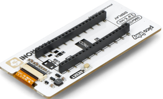
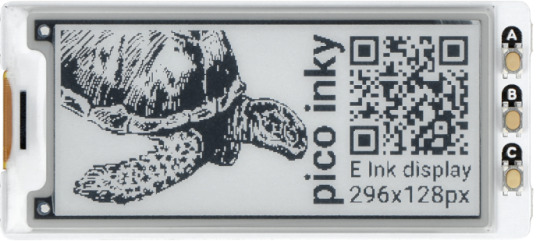
Bild zeigt die Rückseite und Vorderseite des pico Inkey.
Das ist eines der Dinge wor dieses Display Vorteile hat, weil es allein dadurch bereits so einfach in der Handhabung ist. Das reine Display gibt es bei Pimoroni auch zu kaufen. Das könnte ggf. von Interesse werden, wenn man einmal ein Display austauschen müsste. An diesem Punkt sei angemerkt, dass es das gleiche Display ist, welches auch auf Pimoronis Badger2040, etc. verwendet wird.
Drei Druckknöpfe stehen zur Verfügung, welche man programmieren kann. Eine Pin-Buchsenleiste ist wie gesagt vormontiert und man benötigt zusätzlich nur noch den Raspberry Pi Pico selbst mit gelöteten Pins. Dann aber heißt es PicoW draufstecken und loslegen. Programmiert werden kann dann beispielsweise mit Micropython und so kann das kleine Diplay allerlei gute Dienste leisten. Einige Anwendungsbereiche kommen wir da in den Sinn. Als Namensschild oder um Ware auszuzeichnen oder für allerlei andere sinnvolle oder lustige Dinge. Und wegen der schnellen Aktuallisierungsrate dieses eInk Display sogar auch als Uhr!
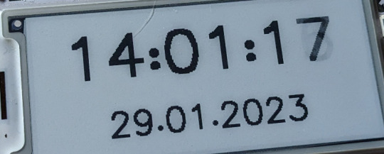
Bild zeigt die Verwendung eines eInk Displays als Uhr.
Da der Pico W Verwendung findet steht uns der Uugang zum Internet offen und wir können uns allerlei Infos aus dem Web ziehen und anzeigen. Und das Display löst uns ein ganz wichtiges Problem. Es kann uns die IP Adresse anzeigen , welche der Pico W in unserem WLAN bekommen hat. Und das ist ziemlich cool. Lasst mich ein Beispiel geben warum. Stellt euch vor Ihr verendet den Pico W als Teil eines Smart-Homes. Der Pico W dient dabei als kleiner Webserver, stellt uns also eine Website zur Verfügung, welche eben unter der ihm zugewiesenen IP Adresse aufrufbar ist. Mit einem angeschlossenen Relais kann so ein Pico dann bspw. eine Lampe ein- und ausschalten.
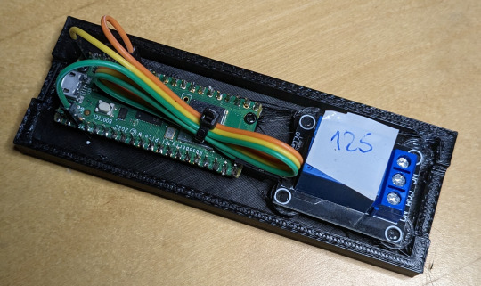
Bild zeigt einen Raspberry Pi Pico W mit einem Relais zur Smarthome-Steuerung um einen Verbraucher zu schalten.
Aber nun kommt der springende Punkt. Solange der Pico W via USB Kabel mit dem Computer und bspw. der Thonny IDE verbunden ist, können wir über das Terminal Fenster mitlesen was der Pico so treibt. Und so können wir uns auch ansehen, wenn er sich mit dem WLAN verbindet und welche IP Adresse er bekommen hat. Die könnte sich freilich auch mal ändern, wenn die vom Router dynamisch IP Adressen vergeben lassen.
Hängt der Pico W aber dann später ggf. nicht mehr am Computer, sondern an einem beliebigen Bestimmungsort, wo er nur Strom zum Betrieb erhält, so sieht die Sache eben anders aus. Jetzt aber könnten wir auch noch mit Hilfe des pico inky Displays die IP Adresse anzeigen lassen. Ziemlich cool!
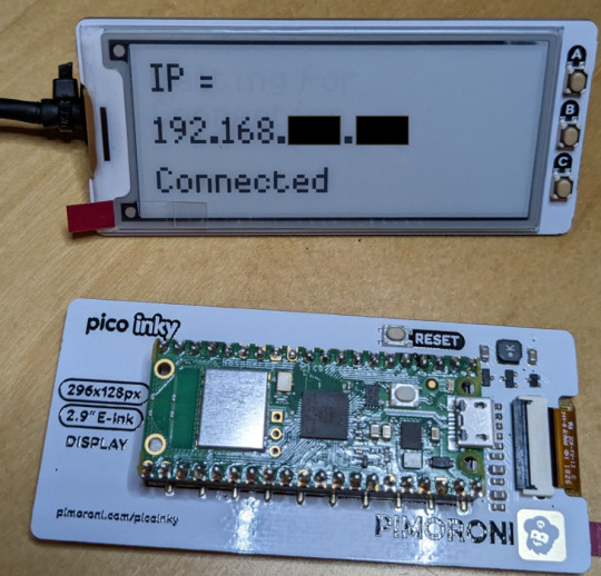
Bild zeigt den Raspberry Pi Pico mit dem montierten pico inkey Display für die Anzeige der IP Adresse.
Und wieder einmal ist bewiesen, dass uns Pimoroni nicht nur lustiges Spielzeug, sondern auch echt nützliches Zubehör liefert. Das ist nun einer der Beiträge meiner aktuellen Beitrags-Serie, die ich kurz "Pimorini Woche" "genannt habe. Wenn Ihr möchtet folgt mit auf Twitter und bleibt aktuell, denn da kommt noch mehr.
Hier nun noch der Link zum Produkt: pimoroni.com pico inkey
0 notes
Photo

Looking for a good platform to build a drink dispensing machine
I'm building a liquid dispensing/vending machine. Here are the features it'll have:
The machine will have a big touchscreen and user can interact with it and select her options. It should also have a capability to show animations/videos.
It'll have motors to control the flow of different fluids and dispense some liquids. It is controlling around 12-15 sensors, and 12-15 motors/relays, probably a camera.
Machine also needs to have a payment method integration.
Also, it should be connected to internet and receive commands from a smartphone app/web and send some sensor information to a common database.
My questions are:
What kind of software and hardware platform should be used here? I am thinking of Android things running on a Raspberry Pi. Other options are Ubuntu on a Pi/similar board. Have you had any positive experience with Android things?
Please feel free to ask any details that I may have missed. Thanks!!
2 notes
·
View notes
Text
Relay Shield for Raspberry Pi | Raspberry Pi Relay Board by SB Components
PiRelay - Relay Shield for Raspberry Pi, Raspberry Pi Relay Board
Raspberry Pi relay Board helps you to control high voltage and make your appliances intelligent, It could be a nice solution for controlling devices that could not be directly controlled by RPi's Digital I/Os. The standardized shield form factor enables smooth connection with Raspberry Pi and compatibles. @raspberrypigk @raspberrypi-piface @microbits
#Raspberry Pi#Relay board#Relay shield#relayshield#Raspberry pi relay board#Raspberry pi relay shield#Relay shield for raspberry pi
1 note
·
View note