#Surface Mount capacitor
Explore tagged Tumblr posts
Visit Tumblr Blog
Explore Tumblr blogs with no restrictions, modern design and the best experience.
Last Seen Tumblr Blogs


Fun Fact
When “GIF” was named word of the year in 2012, Oxford Dictionaries U.S.A. credited Tumblr for pushing the word.
Text
Fixed capacitor, Capacitor array, Surface Mount capacitor, Ceramic disc capacitor
0603 10 uF 10 V ±20% Tolerance X6S Multilayer Ceramic Chip Capacitor
0 notes
Note
hi! it's so nice to see you posting again - i hope you someday mess with the new 2023 furbys, im very intrigued by them! i wanted to ask if you know how to modify the resting position of a non-working furby? my blue turtle is unsalvagable (his battery contacts are completely eroded) but hes stuck bending forward. is there any way to move his motors back into the flat resting position? thanks for any help!
Thank you! Currently, I don't think I'm likely to tinker much with the new Furbies- I'm not as interested in any of the more recent models because they're harder to work on/not as well documented, and I can't justify the cost. The only reason I ever got to disassemble a Connect is because someone I know wanted one anyway, and they found a non-functional one cheap at a local thrift store!
For your leaning '98 Furby, you'll be able to put him in whatever position you like by manually moving his gears, just like trying to push-start. It might take a while depending on where he stopped moving, but eventually he'll sit back up.
#i don't recall if i ever posted about the connect i took apart here#but that was the one that just had a loose surface-mount capacitor rattling around in the shell#i STILL don't know where it came from
9 notes
·
View notes
Video
chips by Francois Flibotte Via Flickr: Detailed view of a printed circuit board (PCB), showcasing its complex electronic components and their interconnections. The image focuses on surface-mount devices (SMDs) and other electronic parts soldered to the PCB, revealing its intricate design and functionality.
#capacitors#circuit board#connectors#electronic components#hardware#integrated circuits#resistors#surface-mount devices#Montreal#Quebec#Canada#flickr
0 notes
Text
https://www.futureelectronics.com/p/passives--capacitors--ceramic-capacitors--multilayer-ceramic-capacitors/grm21br61a476me15l-murata-7072395
What is a ceramic capacitor, Surface Mount Multilayer Ceramic Capacitor
0805 47 uF 10 V ±20% Tolerance X5R Multilayer Ceramic Chip Capacitor
#Murata#GRM21BR61A476ME15L#Multilayer Ceramic Capacitors#Surface Mount Multilayer Ceramic Capacitor#Murata capacitors#Ceramic Capacitors chip#Data processing#Fixed capacitor#Ceramic capacitors#capacitor#High voltage#capacitor ceramic
1 note
·
View note
Text
https://www.futureelectronics.com/p/passives--capacitors--ceramic-capacitors--multilayer-ceramic-capacitors/08055c104kat2a-kyocera-avx-9165915
What is multilayer ceramic capacitor, capacitors ceramic, capacitor manufacturer
0805 100nF 50 V ±10 % Tolerance X7R Surface Mount Multilayer Ceramic Capacitor
#KAVX#08055C104KAT2A#Ceramic Capacitors#Multilayer Ceramic Capacitors#capacitors ceramic#capacitor manufacturer#MLCCs#capacitor ceramic#ceramic capacitor#Surface Mount Multilayer Ceramic Capacitor#High voltage ceramic capacitor
1 note
·
View note
Text
https://www.futureelectronics.com/p/passives--capacitors--tantalum-capacitors/taja106k016rnj-kyocera-avx-7015456
Low ESR Tantalum Capacitor, Surface Mount Standard Tantalum Chip Capacitor
TAJ Series 10 uF ±10% 16 V Surface Mount Standard Tantalum Chip Capacitor
#Capacitors#Tantalum Capacitors#TAJA106K016RNJ#KYOCERA AVX#Low ESR#Surface Mount Standard Tantalum Chip Capacitor#chip#Standard Molded Tantalum Capacitor#application#Solid tantalum capacitor#Wet tantalum capacitor
1 note
·
View note
Text
https://www.futureelectronics.com/p/passives--capacitors--tantalum-capacitors/293d226x96r3a2te3-vishay-3570074
Capacitors, Tantalum Capacitors, 293D226X96R3A2TE3, Vishay
293D Series 22 uF ±10 % 6.3 V Surface Mount Standard Molded Tantalum Capacitor
#Capacitors#Tantalum Capacitors#293D226X96R3A2TE3#Vishay#electrolytic capacitors#tantalum capacitor1 uf#10uf tantalum electrolytic capacitor#Vishay tantalum chip capacitors#Surface Mount Molded Solid Tantalum Capacitor#wet tantalum capacitors
1 note
·
View note
Text
https://www.futureelectronics.com/p/passives--capacitors--tantalum-capacitors/6tpe470mi-panasonic-4051475
Wet tantalum capacitors, Low ESR Tantalum Capacitor, Panasonic capacitor
TPE Series 470 uF ±20% 6.3 V Surface Mount Polymer Solid Tantalum Capacitor
#Capacitors#Tantalum Capacitors#6TPE470MI#Panasonic#Types of Tantalum Capacitor#10uf tantalum chip#tantalum chip#Wet tantalum capacitors#Low ESR Tantalum Capacitor#Panasonic capacitor#Surface Mount Polymer Solid Tantalum Capacitor
1 note
·
View note
Text
https://www.futureelectronics.com/p/passives--capacitors--aluminum-organic-polymer/eeh-za1v680xp-panasonic-2034554
Surface Mount Polymer Chip Capacitor, Multi section capacitor, capacitors
ZA Series 35 V 68 uF Ø 6.3 x 7.7 mm Surface Mount Polymer Chip Capacitor
#Panasonic#EEH-ZA1V680XP#Capacitors#What is an Aluminum Organic Polymer capacitor#Solid#Reforming electrolytic#Polymer Aluminum Cap Conductive#Surface Mount Polymer Chip Capacitor#Multi section capacitor#capacitors
1 note
·
View note
Text
Sharing a Computer with More Friends
A few months ago I built an I/O expansion board for my homebrew 68030 project with a 4-port serial card to go with it, and got BASIC running for four simultaneous users. It worked, but not as well as I had hoped. I wanted to be able to run two of those serial cards to support 8 total users, but it had proven unstable enough that with just the one card I had to slow down the whole system to 8MHz.
So I designed a new serial card.

I had previously been running this computer without any issues at 32MHz with a mezzanine card with FPU & IDE as well as a video card. The main board by itself can clear 56MHz. Having to go all the way down to 8MHz just didn't sit well with me. I want this machine to run as fast as possible for its 8 users.
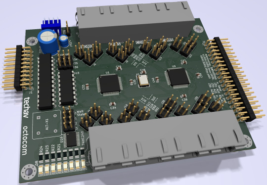
I put extra time into reviewing worst-case timing for all components and graphing out how signals would propagate. The 16C554 quad UARTs I'm designing around are modern parts that can handle pretty fast bus speeds themselves — easily up to 50MHz with no wait states on the 68030 bus — assuming all the glue logic can get out of the way fast enough.
Signal propagation delays add up quickly.
My first draft schematic used discrete 74-series logic for chip selection, signal decoding, timing, etc. At slower bus speeds this wouldn't have been a problem. But I want this thing to run as fast as possible. By the time critical signals had made it through all those logic gates, I was looking at already being well into one wait state by the time the UART would see a 50MHz bus cycle begin.
I needed something faster. I was also running low on space on the board for all the components I needed. The obvious answer was programmable logic. I settled on the ATF22V10 as a good compromise of speed, size, availability, and programmability. It's available in DIP with gate delays down to 7ns. Where discrete gates were necessary, I selected the fastest parts I could. The final design I came up with showed a worst case timing that would only need one wait state at 50MHz and none for anything slower.
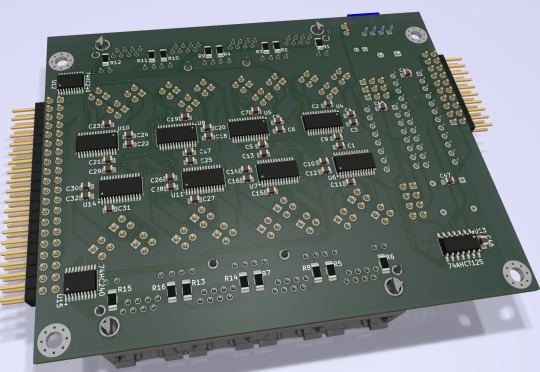
It ended up being a tight fit, but I was able to make it work on a 4-layer board within the same footprint of my main board, putting some components on the back side. (It may look like a bunch of empty space, but there's actually a lot going on running full RS232 with handshaking for 8 ports).
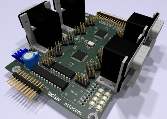
New problem. I had blown my budget for the project. As much as I love those stacked DE9 connectors, they're expensive. And there's no getting around the $10 pricetag for each of those quad UARTs. Even using parts on-hand where possible, I was looking at a hefty Mouser order.
[jbevren] suggested using ganged RJ45 connectors with the Cisco pinout instead of stacked DE9, to save space & cut costs. [Chartreuse] suggested buffering the TTL serial TX/RX signals to drive the LEDs that are frequently included on PCB-mount RJ45 connectors. Both great ideas. I was able to cut 20% off my parts order and add some nice diagnostic lights to the design.
Two weeks later, I received five new PCBs straight from China. I of course wasted no time setting into starting to assemble one.
I really set myself up for a challenge on this one. I learned to solder some 25 years ago and have done countless projects in that time. But I think this might be the most compact, most heavily populated, most surface mount board I've ever assembled myself. (There are 56 size 0805 (that's 2x1.2mm) capacitors alone!)


After a few hours soldering, I had enough assembled to test the first serial port. If the first port worked then the other three on that chip should work too, and there's a great chance the other chip would work as well.

And it did work! After some poking around with the oscilloscope to make sure nothing was amiss, I started up the computer and it ran just fine at 8MHz.
And at 16MHz.
And at 25MHz.
And at 32MHz.
And at 40MHz.
And almost at 50MHz!
Remember what I said about my timing graphs showing one wait state for 50MHz? The computer actually booted up and ran just fine at 50MHz. The problem was when I tried typing in a BASIC program certain letters were getting switched around, and try as I might, BASIC just refused to 'RQN' my program. It was pretty consistently losing bit 3, likely from that signal having to travel just a tiny bit farther than the others. A problem that will probably be resolved with an extra wait state.
Good enough for a first test! A few hours more and I finished assembling the card.

I did have some problems with cleaning up flux off the board, and I had to touch up a few weak solder joints, but so far everything seems to be working. I've updated my little multi-user kernel to run all 8 users from this new card and it's running stable at 40MHz.
I need to update my logic on the 22V10 to fix a bug in the wait state generator. I would love to see this thing actually running at 50MHz — a 25% overclock for the 40MHz CPU I am currently running. I also want to expand my little kernel program to add some new features like the ability to configure the console serial ports and maybe even load programs from disk.
I hope to bring this machine with a collection of terminals and modems this June to VCF Southwest 2025 for an interactive exhibit that can be dialed into from other exhibits at the show.
#wrap030#multi-user BASIC#EhBASIC#homebrew computer#motorola 68030#68030#mc68030#motorola 68k#vcfsw#vcfsw2025#Retrocomputing#rtc#retrotech crew
31 notes
·
View notes
Note
Corax woke to the sound of a softly snoring Robert Harwood. The grizzled mercenary leader was still asleep. Robert's head was buried face down in the plumage on Corax's upper chest. Corax lay in the functional, if comfortable, bed, and took in the sights of the room around him - there had been little time to do so six - neg, eight - hours earlier. Upon their arrival, it had been two minutes of frantic (and drunken, in Robert's case) undressing, an hour and a half of intense, intimate, and wall-shakingly loud coupling - Robert face down or otherwise receiving for much of it - then thirty minutes of afterglow, a quick fifteen minute shower tandem shower, and finally, sleep for the remainder of the time elapsed. Corax decided he would allow Robert as much sleep as he desired. So he looked around the room - his genetically-augmented avian night vision allowing him a good view of everything, even in the dark - at the bare metal walls, the holovid player and CD audio system on the far wall, the open door to the surprisingly well appointed bathroom... it was a nice, if functional, room. Not as well-appointed as the Argo's quarters, but better than the barracks and sibko facilities Corax had been raised in. Idly he ran his taloned hands softly across Robert's still naked back, as his mind began to wander... there are adjustments for hot drop that needed to be made to the Haast Eagle before we drop, and the stravag PPC was still showing a .085% transfer inefficiency with the capacitor off-line - but he shook off those thoughts. He wanted to take Robert there, and show him. Every Mech pilot, and many Aerospace pilots, found LAMs an alluring, fascinating, "dead end" technology, but the Haast Eagle was the first to be built since the Jihad. It was the first of a new generation - especially since the Argo's prodigy of an engineering whiz-cum-electronics sorceress Jaela Yang-Murad had cracked the problem of mounting Ferro-Fibrous armor to a LAM.
So he lay, thinking, stoking his sleeping coupling partner's back, breathing, and feeling very content.
( @is-the-battlemech-cool-or-not )
After a while, at precisely 5:00 Taurian Standard Time, (though Corax had no way of knowing that), Robert's eyes opened, quickly snapping around the room until they settled on Corax. For a moment, his bleary eyes widened, and his jaw went slack with awe, but as the fog of sleep cleared, recognition came over him, and he schooled his expression back to pleased neutrality.
"Mornin', Nevermore," Robert says. "Nice of you to to stick around. I'm led to understand that with you Clan folk it can be a bit of a 'Wham, bam, thank you ma'am' type situation." He sits up in bed, joints making all sorts of creaks and cracks from decades of abuse. He leans over the edge of the bed, pulling himself closer to the edge.
After a moment’s looking, he turns back to Corax with a slightly annoyed expression.
"Alright, where the hell are my limbs. I'm too hungover to remember taking them off, and I need them if I'm gonna make us coffee and breakfast." He says, gesturing with his arm to the three mounting surfaces that adorn his other arm and legs.
31 notes
·
View notes
Text
I've been working on this for a long time, and I still didn't go over everything I want to go over, so this is going to end up being a multi part series on how I make my wavs, as well as a bit of general audio engineering.
Reed Behind the Scenes Part One:
Microphones and Recording Environment
A couple of notes before we begin:
For this series I'm going to focus on audio recordings, not video recordings, as they are very different mediums with different requirements. I am by no means an expert, I just have a little more experience with audio production than the average person.
All of my equipment is in the Android/Microsoft ecosystem, and as such I do not have much experience with Apple products. I apologize in advance if anything I discuss does not work within the Apple ecosystem.
Let's talk about microphones. You can't make a recording without one, whether it's the one in your phone or a standalone mic. I use the latter, but some phones have decent mics. Since we just mentioned Apple products, I will say that I have heard that the microphones in iPhones are pretty good these days. When I record on my phone, I prefer to use a dedicated recording app, because it allows me to record directly to an mp3 or wav file that I can then export to my computer for editing, as opposed to recording a video and trying to rip the audio later. I use an app called Voice Record Pro, but there are plenty of voice recording apps out there.
For my best quality work, I use my microphone. You don't need a super fancy mic to make good recordings, but the kind of mic you get is important. There are many different kinds of mics at many different price points, but they generally fall into two categories: USB and XLR. USB microphones can plug directly into your computer, whereas XLR mics need to pass through an interface first. For the vast, vast majority of people looking to get a mic for making fetish content, I am going to recommend getting a USB mic, and the main reason is cost.
For XLR mics, you need two pieces of equipment: the mic itself and an audio interface to run it through to a computer. Not to mention XLR cables, a stand, and a mount. Even if you get a relatively inexpensive XLR mic, after you get all of the other equipment and accessories you need, you may as well have splurged on a decent USB mic.
I only recommend investing in a good XLR if you want to pursue a professional audio career of some kind, and even then I'd wait to sink serious money into it until after you've gotten your feet wet and know that it's really what you want to do. These can be very difficult industries to break into. I do professional voice work, so for my setup I have a Neumann TLM 103, Focusrite Scarlett Solo audio interface, and a Surface Go tablet for recording. More on that in a bit.
In both USB and XLR there are generally three types of microphone: condenser (which is also sometimes called capacitor), dynamic, and ribbon. I'm not going to get into ribbon mics, because you don't need one just for snz content, and I'm not well-versed in them anyway. Most of the mics you will encounter when shopping for one online will be either condenser or dynamic.
Condenser mics are more sensitive than dynamic mics, so they're generally clearer and better suited for voice work. I'm using the word “generally” a lot here, because there's such a wide range of mics, and you may very well find a dynamic mic that works better for your voice and your space than a condenser mic. Unfortunately, the only way to really know for sure is to get one, try it out, and return it if it doesn't fit your needs.
There's this idea that dynamic mics are better for untreated spaces, because they're less sensitive and will therefore pick up less background noise. That's not exactly true. Dynamic mics do pick up fewer audio frequencies than condenser mics, so if you have some background noise that's outside of your mic’s frequency range, then that may not get picked up. Your average background noises, though—loud neighbors, motorcycles and trucks driving by, your cat meowing, the hum from your PC fan—those sounds will still get picked up. The best thing to do is to sound treat your space, but we'll get to that later.
I'll post a few recommendations, but I haven't used any of these mics for myself, so these are recommendations from the voice acting community at large as good budget mics. Any prices are USD, and unfortunately I don't know the global availability of these mics.
USB Mic Recommendations:
Blue Yeti USB
AudioTechnica AT2020 USB (Note that there is also an XLR version.)
Both can be purchased under $100 pre-owned. Both retail for around $130 new. If you're in the US, the nice thing about the Blue Yeti is that you can walk into just about any Best Buy and pick up a brand new one on the spot.
XLR Mic Recommendations:
RØDE NT1 5th Gen
AudioTechnica AT2020 XLR (As mentioned above.)
The AT, at about $100 new, costs less than half as much as the RØDE at $250. If you're set on an XLR but shopping on a budget, that may be the mic for you. The RØDE, on the other hand, is a great introductory mic for professional voice work. For these mics you'll need an audio interface, also called a preamp. A solid one for the budget-conscious, and what I use, is the Focusrite Scarlett Solo, which will set you back about $100 new.
The microphone I use, a Neumann TLM 103, retails for about $1,200 new. You can sometimes find them under $600 pre-owned. They're pretty much the gold standard in the animation industry for how well they can handle loud sounds, like yelling and screaming, without clipping. I invested in one several years ago when my husband got a nice bonus from work, for which I am eternally grateful. Do not go this far unless you are serious about voice work.
Now that you've learned far more about microphones than you ever wanted, let's talk about sound treatment for your recording space. Whether you're using a dedicated mic or your phone, sound treatment will always elevate the quality of your recordings. Even the highest quality mic in an untreated space will sound worse than an average quality mic in a well-treated space.
What is sound treatment? Sound treatment is taking steps to reduce and eliminate the amount of background noise and reverb from the space you are recording in. Have you ever noticed a slightly echoey quality to your voice in recordings? Like you can "hear the room"? That's reverb. When you speak, the sound waves go from your mouth to the microphone , but they also go out into the room and reflect off of the walls before coming back and hitting the microphone again, creating that slight echo. You'll need a sound treated space to prevent that from happening.
One fairly easy and inexpensive way to do this is to utilize thick moving blankets. You can try tacking them up in a closet or hanging them from a booth frame. I currently use a recording booth made from a PVC pipe frame with a double layer of moving blankets hung around it and draped overtop. (Here’s a link to a video tutorial on how to build your own). Another method is to use sound dampening panels hung on the walls of your recording space. A lot of folks use those textured foam tiles. Just be careful with those because if you get really cheap ones the foam can be poor quality that doesn't dampen sound very well. (The Foam Factory sells great acoustic foam, but the cost can add up quickly depending on the size of your space.)
I've also seen booths that are made by lining the walls of a closet with carpeting, so if you happen to have some carpet remnants that might work for you. I’m upgrading my own recording space by converting a closet into a recording booth. I'm building sound panels made from wooden frames filled with sound dampening insulation that I’ll hang on the walls. (Here's a link to that tutorial as well, but that option costs a few hundred dollars in supplies.) If nothing else, a closet filled with hanging clothes can do in a pinch to dampen background noise.
Let's talk a little bit about computers while we're on the topic of background noise. Remember way back when I mentioned my Surface Go tablet? Now remember when I talked about how mics can pick up PC fans? The Surface Go is how I get around the problem of PC fan background noise. The Surface Go doesn't have a fan, so it doesn't make any noise. I can bring it into the booth with me, hook my interface up to it, and use it to run my recording software. I'll then transfer the file to my main PC for editing. If you can do so with your space, you could potentially get cables that are long enough to leave your PC tower outside of the recording space so you can't hear the fan. Definitely cheaper than buying a tablet just for recording.
For editing, I use Audacity, which is a free digital audio workstation, or DAW. Another popular DAW is Reaper, which is "free" in that they don't limit the trial version, so you don't need to pay to use the full version (although they'd really like you to buy a license). I'm not going to go too far into depth on software and editing here, since I plan to do a Part Two on how I edit my recordings. Besides, this post has gotten long enough, and this seems as good a place as any to end it. I'm always open to questions on this kind of thing. Like I said, I'm not an expert, but I'll answer what I can, and if I don't know the answer I'll do my best to find the information for you. Thanks for reading this far, and I hope you've learned something that's helpful or at least interesting to you in some way 😊
9 notes
·
View notes
Text

I repaired this sick ass digital clock I got from a thrift store very cheaply a few years ago. It's just a floating LCD panel and I think it looks so frigging amazing. (Really makes me think of that cool Dutch YouTuber, Posy, and his love of LCD panels. (And I'm like "hell yeah!! There's so much beauty in the mundane!!! Just look how frigging cool this clock is!!"))
Anyhoo, it wasn't working when I got it. Probably why it was so cheap.
It has a little on/off switch on the back, but nothing would happen when you flipped it, but sometimes if you held its solar panel under a very bright light the clock would turn on
...for one second
before turning off again
and then back on again.
Very rhythmically.
So there was still some life left in the old girl... somewhere... 🤔
Unscrew the back of it and have a look see.
Discover a pair of circuit boards, one of which has a cr2032 coin cell clamped onto it. Hooray, a Vital Clue!
Fortunately, I have one of those batteries lying around. A second spare from when I replaced the batteries in some Digimon v-pets.
So I replace it.
Aaaaand nothing happens...
:(
Next step: fully disassemble the clock to look for More Clues.
Discover that its LCD panel isn't wired in to anything. There's just a row of teeny tiny contacts along its base which press up against a matching row of teeny tiny contacts along its control board, held together by the frame of the clock and a kind of thin pink foam buffer ring around the contacts. Very cool!
(Like two mouths kissing but only one of them has any lips. 😆)
Examine the two circuit boards under a loup. Maybe there's a visibly-broken component!
(I hope there's a visibly-broken component, else I have to dig out my multimeter and start systematically testing them one by one)
(I hope there aren't any visibly-broken components. If it's the quartz crystal or one of the two capacitors, then I might be able to replace it, because those are regular-sized, through-hole, components; but if it's one of the surface-mount resistors then I'd have to scrap the whole clock, because I just don't have the tools, experience, or know-how to deal with those microscopic little guys... :/ )
There aren't any visibly-broken components. Phew, but also consternation, because now what?
But hmm, there are some teeeeny tiny white flecks of crusty residue here and there over the circuit boards... I guess the old battery must have leaked at some point?
I gently scrape them off with the tip of a very fine pair of tweezers and then reassemble the clock enough to test it.
(LCD panel & solar panel back into front-frame, control board back over them to hold them into place and make contact with the LCD; everything else [coin-cell daughterboard, piezo buzzer, and the user-input buttons] dangling free in the breeze Winnie-The-Pooh-style)
It turns on! It chirps out a happy little song of high-pitched beeps!! It blinks "12:00" at me!!!

I fully reassemble the clock with a song in my heart and set its time and date.
Goddamn this clock looks so cool. 🥰
7 notes
·
View notes
Note
So, uh, I may have attached a less than reputable manufacturer's nexus weapon to my Lancaster, issue being the weapon doesn't seem to want to leave, nor does the same manufacturer's NHP. Any recommendations?
That is a rather concerning issue. While we do empathize with the weapon’s desire to spend more time with a well-built IPS-N mechanized chassis, we are very sorry to hear that other manufacturers do not hold themselves to the same quality control standards as we do.
Fortunately, your Lancaster comes pre-equipped with a solution to such a problem. Here’s a step-by-step guide:
Make sure your core power capacitor is charged.
Remove the back panel from the mounting for the “Wingman” Latch Drone. Pull the drone out of its tube.
Directly connect the drone to the core capacitor using the provided power cables. Attach the drone to the outer surface of the Lancaster.
Power it on from a safe distance. This should create a feedback loop within the reactor that the unwanted systems will not be able to handle.
Allow this to continue until the reactor forcibly shuts down. You should now be able to remove the unwanted equipment from the mech.
And there you have it! If you have any further questions, please don’t hesitate to reach out. Good luck, pilot!
21 notes
·
View notes
Text
What is PCB Assembly ?
PCB Assembly manufacturer - Hitech Circuits Co., Limited
It’s the step in the manufacturing process in which you populate a blank board with the electronic components needed to make it into a functional printed circuit board. It’s these components that make a board into the circuit that enables an electronic product to function. PCB assembly typically takes place via one of two processes:
1. Surface-mount technology
SMT: SMT stands for “Surface Mount Technology“. The SMT components are very small sizes and comes in various packages like 0201, 0402, 0603, 1608 packages for resistors and capacitors. Similarly for Integrated circuits ICs we have SOIC, TSSOP, QFP and BGA.
The SMT components assembly is very difficult for human hands and can be time taking process so it is mostly done by automated pick and place machine.
2. Through-hole manufacturing
THT: THT stands for “Through hole Technology”. The components with leads and wires, like resistors, capacitors, inductors, PDIP ICs, transformers, transistors, IGBTs, MOSFETS are example.
The component has to be inserted on one side of PCB and pulled by leg on other side and cut the leg and solder it. The THT components assembly is usually done by hand soldering and is relatively easy.
Printed Circuit Board Assembly Techniques
There are only two common PCBA techniques available for use by a PCB designer. The methods are:
1. Automated PCB Assembly Techniques
Generally, this technique employs the use of state of the art machines, which are fully automatic. For example, the surface mount components are worth positioning with the aid of an automated pick and place machine.
Again, reflow soldering is commonly for surface mount components usually done in a reflow oven. An automated solder stencil is also used to apply the solder paste on the PCB.
Finally, high tech inspection machines are used to confirm and check the quality of the PCBA. Some of which include: Automated optical inspection machine (AOI), X-ray inspection machines, etc.
Above all, due to the precise monitoring, control of soldering, no human input and versatile machines.
This technique ensures utmost efficiency, output consistencies, and limits defects.
2. Manual PCB Assembly Techniques
This method is favorite for use with through-hole parts, which needs manual placement on the board. Besides, with these through-hole parts, it’s advisable you use wave soldering. Note that in the through- hole assembly process, you need to place the components and electronics on the PCB.
After that, you use wave soldering to solder the leads. Typically, you will need an individual to insert a component into a marked PTH. Once done, transfer the PCB to the next station where the next person will be on standby tasked with fixing another part.
What are the Benefits of SMT PCB Assembly?
SMT assembly provides many benefits and some of them are as follows:
It can be used to incorporate small components.
In SMT, the components can be placed on both sides of the board.
It assures high component densities.
Fewer holes need to be drilled for surface mounting than through-hole.
It require low initial costs and time for setting up the mass production.
SMT is the simpler and faster-automated assembly when compared to through-hole.
Errors regarding the component placement can be easily rectified.
Surface mount PCBs feature strong joints, which can easily withstand vibrations.
What are the techniques used in Surface Mount Technology?
There are several techniques for the reflow process. After applying the solder paste or a flux mixture on the board and after placing the components, the boards are conveyed to a reflow soldering oven. The techniques used for reflowing soldering include infrared lamps, hot gas convection, fluorocarbon liquids with a high boiling point, and so on.
What are the different testing methods used in SMT PCB Assembly?
Hitech Circuits as the PCB assembly manufacturer, we perform the following testing and inspection to ensure the quality of surface mount PCBs.
Automated Optical Inspection (AOI): This is performed before and after the soldering to identify the component placement, presence, and solder quality.
X-ray Testing: In this type of testing, the operator relies on the X-ray images of the PCB to check the solder joints and lead-less components such as Quad Flat Packs and ball grid arrays, which are generally not visible to naked eyes.
In-Circuit Testing (ICT): This method is used to detect manufacturing defects by testing the electrical properties in the SMT Assembly.
What type of files or documents should I send for SMT PCB Assembly?
Gerber Files: The file contains all details of physical board layers including solder masks, copper layers, drill data, legends, and so on.
Bill of Materials (BOM): This contains information on the list of items needed for the PCB manufacturing and the instructions of manufacturing.
Pick and Place File: This file contains information on all components to be used in the PCB design and their rotation and X-Y coordinates.
The whole process of PCB Assembly
1. Bare board loader machine
The first step in the PCB assembly is to arrange the bare boards on the rack, and the machine will automatically send the boards one by one into the SMT assembly line.
2. Printing solder paste
When PCB on the SMT production line, firstly, we have to print solder paste on it, and the solder paste will be printed on the pads of the PCB. These solder pastes will be melt and solder the electronic parts to the circuit board when it passes through the high-temperature reflow oven.
In addition, when testing new products, some people will use film board/adhesive cardboard instead of solder paste, which can increase the efficiency for adjusting the SMT machines.
3. Solder paste inspection machine(SPI)
Since the quality of solder paste printing is related to the quality of welding of subsequent parts, some SMT factories will use optical machine to check the quality of solder paste after printed the solder paste in order to ensure stable quality. If there any poorly printed solder paste board, we will wash off the solder paste on it and reprint, or remove the excess solder paste if there is redundant solder paste on it.
4. High speed SMT machine
Usually, we will put some small electronic parts (such as small resistors, capacitors, and inductors) to be printed on the circuit board first, and these parts will be slightly stuck by the solder paste just printed on the circuit board, so even if the speed of printing is very fast and the parts on the board will not fall away. But large parts are not suitable for use in such high speed SMT machines, which will slow down the speed of small parts assembly. And the parts will be shifted from the original position due to the rapid movement of the board.
5. Universal SMT machine
Universal SMT machine is also known as "slow machine", it will be assembled some large electronic components, such as BGA IC, connectors, etc., these parts need more accurate positions, so the alignment is very important. Use a camera to take a picture to confirm the position of the parts, so the speed is much slower than High speed SMT machine we taked before. Due to the size of the components here, not all of them are packed in tape and reel, and some may be packed in trays or tubes. But if you want the SMT machine to recognize the trays or tube-shaped packaging materials, you must configure an additional machine.
Generally, traditional SMT machines are using the principle of suction to move electronic parts, and in order to place the parts successfully, and there must be the flat surface on these electronic components for the suction nozzle of the SMT machine to absorb. However, for some electronic parts don’t have a flat surface for these machines, and it is necessary to order special nozzles for these special-shaped parts, or add a flat tape on the parts, or wear a flat cap for thees electronic parts.
6. Manual parts or visual inspection
After assembled all parts by the high speed SMT machine or Universal SMT machine and before going through the high-temperature reflow oven, and we will set up a visual inspection station here and to pick out the deviation parts or missing components boards etc., because we have to use a soldering iron to repair if there are still defectives boards after passing the high-temperature oven, which will affect the quality of the product and will also increase the cost. in addition, for some larger electronic parts or traditional DIP parts or some special reasons cannot be processed by the SMT machine before, they will be manually placed on pcb here.
7. Reflow oven
The purpose of reflow oven is to melt the solder paste and form a non-metallic compound on the component feet and the circuit board, that means to solder electronic components on the circuit board. The temperature rise and fall curves often affect the soldering quality of the entire circuit board. According to the characteristics of the solder materials, usually the reflow oven will set the preheating zone, soaking zone, reflow zone, and cooling zone to achieve the best soldering effect.
For example, the melting point for SAC305 solder paste with lead-free is about 217°C, which means that the temperature of the reflow oven must be higher than the melting points to remelt the solder paste. What's more, the maximum temperature in the reflow furnace should not exceed 250°C, otherwise many parts will be deformed or melted because they cannot withstand such a high temperature.
Basically, after the pcb passed through the reflow oven, the assembly for the entire circuit board is almost complete. If there are hand-soldered parts, we need to transfer to DIP process, and then we have to check the quality after reflow oven by QC department.
8. Automatic optical inspection(AOI)
The main purpose of setting up AOI is because some high density boards can’t be process the following ICT test, so we used AOI inspection to replace it. But even using AOI inspections, there still have the blind spots for such checking, for example, the solder pads under the components cannot be checked by AOI. At present, it can only check whether the parts have side standing issue, missing parts, displacement, polarity direction, solder bridges, lack of soldering etc., but cannot checking the BGA solderability, resistance value, capacitance value, inductance value and other components quality, so far AOI inspection can’t completely replace ICT test.
Therefore, there is still some risk if only AOI inspection is used to replace ICT testing, but ICT test is also not 100% make sure the good quality, we suggest these two ways can be combined with together to make sure the good quality.
9. PCB unloader machine
After the board is fully assembled, it will be retracted to the unloder machine, which has been designed to allow the SMT machine to automatically pick and place the board without damaging the quality for PCB.
10. Visual inspection for finished products
Normally there will be a visual inspection area in our SMT production line whether there is an AOI station or not, and it will help to check if there are any defectives after completed assembled the pcbs. If there is an AOI station, it can reduce the visual inspection worker on our SMT line, and to reduce the potential cost, and because it is still necessary to check some places that cannot be judged by AOI, many SMT factories will provide the mainly visual inspection templates at this station, which is convenient for visual inspection worker to inspect some key parts and polarity for components.
11. DIP process
DIP process is a very important process in the whole PCBA processing, and the processing quality will directly affect the functional for PCBA boards, so it is necessary to pay more attention to the DIP process. There are many preliminary preparations for DIP process. The basic process is to re-process the electronic components first, like to cut the extra pins for some DIP components, our staff received the components according to the BOM list, and will check whether the material part numbers and specifications are correct or not, and performs pre-production pre-processing according to the PCBA samples. The steps are: Use various related equipment (automatic capacitor pins cutting machine, jumper bending machine, diode and triode automatic forming machine, automatic belt forming machine and other machines) for processing.

12. ICT test
Printed Circuit board open/short circuit test (ICT, In-Circuit Test), The purpose of ICT test is mainly to test whether the components and circuits on the printed circuit board are open or short issues. It can also measure the basic characteristics of most components, such as resistance, capacitance, and inductance values to judge whether the functions of these parts are damaged, wrong parts or missing parts etc. after passing through the high-temperature reflow oven.
ICT test machines are divided into advanced and basic machines. The basic ICT test machines are generally called MDA (Manufacturing Defect Analyzer). It’s just to measure the basic characteristics of electronic components and judge open and short circuits issue we talked above.
In addition to all the functions of the basic ICT test machines, for advanced ICT test machine can also test the whole PCBA by using power, start to testing the PCBA boards by setting the program in the test machine. The advantage is that it can simulate the function of the printed circuit board under the actual power-on condition, this test can partly replace the following functional test machine (Function Test). But the cost for the test fixture of this advanced ICT test can probably buy a car, it’s too expensive and we suggest it can be used in mass production products.
13. PCBA function test
Functional testing is to make up for the ICT test, because ICT only tests the open and short circuits on the the PCBA board, and other functions such as BGA and other fuctions are not tested, so it is necessary to use a functional testing machine to test all functions on the whole PCBA board.
14. Cutting board (assembly board de-panel)
Normally, printed circuit boards will be produced in panel, and it will be assembled to increase the efficiency of SMT production. It means several single boards in one panel, such as two-in-one, four-in-one etc. After finished all the pcb assembly process, it needs to be cut into single boards, and for some printed circuit boards with only single boards also need to cut off some redundant board edges.
There are several ways to cut the printed circuit board. You can design the V-cut using the blade cutting machine (Scoring) or directly manually break off the board (not recommended). For more high density circuit boards, it will be used the professional splitting machine or the router to split the board without any damage the electronic components and printed circuit boards, but the cost and working hours will be a little longer.
Why Choose Hitech Circuits PCB Assembly Manufacturer for Your PCB Assembly Projects?
There are several PCB manufacturers specializing in PCB assemblyservices. However, Hitech Circuits PCB Assembly stands out owing to the following:
Assistance in Material Procurement:
Technically, in PCB assembly services, the quality of parts is the responsibility of the OEM; however, we ease your job by assisting you to make the right selection. We can help you procure all your parts of the same type own a single part number, thanks to our supply chain and vendor network as well as experience. This saves time and cost that goes in ordering single parts as you plan.
Testing procedures:
We are very focused on quality and thus implement stringent testing procedures at each stage of the assembly and after completion.
Fast Turnaround Times:
Our well-equipped facility and the right tools enable us to complete your requirements well before time, and without compromising on the quality or functioning of the PCBs. For simple designs we revert in 24 to 48 hours.
Cost Effectiveness:
While PCB assembly is a cost-effective alternative, we go a step further and assure that the parts you list are of a good quality and suitable for your requirement. Also, you can control the part flow and replenish them as needed. This eliminates the need to buy extra stock and store it.
Quick Quote:
We offer a quick quote based on your BOM. All you need is a detailed BOM, Gerber files, your application requirement sheet, and quantity.
We’re not one to stand still, which is why we use the latest equipment and the finest minds to create your PCB projects. We’re constantly keeping our finger on the pulse of the latest trends. And as a result, we know how to deliver the highest standards of PCB assembly to meet all your requirements.
Our dedicated, friendly customer service team also means that we support you every step of the way. Offering our expert guidance to ensure a complete PCB project that you’re happy with.
Contact us today
No matter what your printed circuit board assemblyneeds are, we always aim to deliver efficient, dependable solutions. For more information about our services, do not hesitate to get in touch with us today for a no-obligation quote
2 notes
·
View notes