#a36 threaded rod
Explore tagged Tumblr posts
Visit Tumblr Blog
Explore Tumblr blogs with no restrictions, modern design and the best experience.
Last Seen Tumblr Blogs


Fun Fact
12.7% of mobile users access Tumblr.
Text
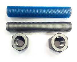
Full Threaded Stud Bolt
We provide best quality and best material of Full Threaded Stud Bolt, Threaded Bar, Threaded Stud, 6Mm-8Mm-10Mm-12Mm Threaded Rod, B7 Threaded Rod, A36 Threaded Rod, Stainless Steel ASTM 193 316H Full Thread Stud Manufacturer in India.
0 notes
Text
Eye Bolts and Eye Nuts Manufacturing Process — Complete Guide
Eye bolts and eye nuts are vital components extensively used in industries like construction, marine, transportation, and lifting applications. These fasteners are designed to create secure anchor points for lifting or rigging heavy loads. Given their critical use, especially in high-load applications, the manufacturing process of eye bolts and eye nuts must adhere to strict quality standards to ensure safety, durability, and performance.
In this comprehensive blog, we will walk through the step-by-step manufacturing process of eye bolts and eye nuts, from raw material selection to final inspection and packaging.
What Are Eye Bolts and Eye Nuts?
Eye bolts are fasteners with a threaded shaft and a loop, or "eye," at one end, designed for lifting or securing loads. They are primarily used to secure ropes, cables, chains, or slings to objects for lifting or tensioning.
Eye Nuts are internally threaded components that are screwed onto externally threaded rods or bolts. They serve a similar purpose as eye bolts, acting as an anchor point for securing loads.
Industrial Applications
Lifting and rigging equipment
Structural anchoring
Marine and offshore applications
Load-bearing attachments
Industrial machinery and assemblies
Utility and power distribution hardware
Raw Material Selection
The manufacturing process begins with selecting the appropriate raw materials, which vary depending on the application and desired properties. Common materials include:
Carbon Steel (e.g., ASTM A36)
Stainless Steel (304, 316 grades)
Alloy Steel
Brass or Bronze (for corrosion resistance)
Galvanized Steel (for outdoor and marine use)
Each material is selected based on factors such as strength, corrosion resistance, temperature tolerance, and mechanical properties.
Manufacturing Process of Eye Bolts
1. Cutting the Raw Bar Stock
The process starts with cutting the raw metal rod or bar stock into appropriate lengths based on the bolt size.
2. Forging the Eye
The bolt's shank is heated in a furnace until it becomes soft and malleable. The heated end is shaped into a circular eye using either a closed-die forging process or an open-die hammer.
For machined eye bolts, the eye is formed by bending the shank and then welding the joint (less common for heavy-duty use due to weaker structural integrity).
3. Trimming and Flash Removal
After forging, excess material (known as flash) is trimmed off to ensure a smooth and uniform shape. This also helps in achieving better dimensional accuracy.
4. Threading
Threads are added to the shank using one of the following techniques:
Thread Rolling: Preferred for high-strength bolts as it displaces material without cutting, preserving grain structure.
Thread Cutting: Used for smaller volumes or special threads.
Threads can be standard (UNC, UNF, or metric) depending on the application.
5. Heat Treatment (Optional)
For high-strength eye bolts, heat treatment like quenching and tempering is done to improve hardness, strength, and fatigue resistance.
6. Surface Treatment / Coating
To improve corrosion resistance and enhance appearance, various finishes are applied:
Hot-Dip Galvanizing
Zinc Plating
Black Oxide Coating
Electropolishing (for stainless steel)
Manufacturing Process of Eye Nuts
1. Raw Material Preparation
Round bars or metal blanks are used to manufacture eye nuts, depending on size and specification.
2. Forging or Casting
Forging: The blank is heated and pressed into shape using forging dies. Forged eye nuts are stronger and more durable.
Casting: Used for decorative or non-load-bearing applications, molten metal is poured into a mold to form the eye nut.
3. Machining and Drilling
The eye nut is then drilled and tapped to create internal threads that match standard bolt sizes. Precision machining ensures accurate dimensions and fit.
4. Threading
Internal threads are machined using tapping machines, often to UNC or metric specifications.
5. Heat Treatment (Optional)
As with eye bolts, heat treatment is applied to improve mechanical properties if required by standards or customer specifications.
6. Finishing / Surface Coating
The surface is polished or coated based on end-use requirements, such as:
Galvanizing
Powder Coating
Zinc Plating
Mirror Polishing (for marine-grade stainless steel)
Quality Control and Inspection
Quality assurance is critical throughout the manufacturing process:
Dimensional Inspection: Using calipers, thread gauges, and micrometers
Load Testing: Eye bolts and nuts are subjected to tensile load testing to ensure safe working load limits
Magnetic Particle Inspection (MPI): For detecting surface cracks
Hardness Testing
Salt Spray Testing: Used to assess the corrosion resistance of coated products.
Compliance with standards like DIN, ISO, ASTM, BS, or ASME is essential for product acceptance.
Packaging and Shipping
Once the components pass all inspections:
They are marked based on their grade, size, and heat number.
Packed in moisture-resistant or customized packaging.
International shipments are packed in export-ready pallets or containers.
Ananka Group – Your Trusted Source for Eye Bolts & Eye Nuts Manufacturing
At Ananka Group, we specialize in manufacturing high-quality Eye Bolts and Eye Nuts using top-grade materials and modern machinery. With a strong focus on precision, safety, and performance, we supply standard and custom fasteners to clients worldwide, catering to various industries and specifications.
Why Choose Us?
In-house Forging & Threading
Adheres to International Standards such as DIN, ASTM, and ISO.
Custom Sizes & Coatings Available
Fast Turnaround Times
Stringent Quality Checks
Conclusion
The manufacturing of eye bolts and eye nuts involves a highly controlled and precise process, starting from material selection to forging, threading, finishing, and quality inspection. These fasteners play a vital role in ensuring safety in critical applications, and their quality must never be compromised.
By choosing a reliable manufacturer like Ananka Group, customers can rest assured of the highest quality and performance of these components.
Frequently Asked Questions (FAQs)
Q1. What is the difference between an eye bolt and an eye nut?
Eye bolts are externally threaded and attached to structures, while eye nuts are internally threaded and screw onto bolts or threaded rods.
Q2. Are eye bolts and eye nuts load-rated?
Yes, especially for lifting applications, they are rated for safe working loads (SWL) based on material and size.
Q3. What standards govern the production of eye bolts and nuts?
Common standards include ASTM A489, DIN 580 (eye bolts), and DIN 582 (eye nuts).
Q4. Can eye bolts and nuts be customized?
Absolutely. Manufacturers like Ananka Group offer custom thread sizes, lengths, coatings, and materials.
Q5. What coatings are best for corrosion resistance?
Hot-dip galvanizing, stainless steel, and zinc plating are ideal for protection against corrosion.
#ananka#anankafasteners#fasteners#fastenersmanufacturer#manufacturing#eyebolts#eyenuts#liftingeyenuts#eyeboltsmanufacturing#boltmanufacturing#articles#blog#manufacturer#tumblr#blog tumblr
0 notes
Text
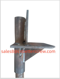
CAP
New Construction Pier Cap
Top Plate Conforms to ASTM A36 for Hot Rolled Carbon Steel
Surface: Hot-Dip Galvanized/Powder Coated or Zinc-plated Pipe Weld 90 Degrees to Plate Pipe material to be ASTM A500 Grade B or C Type1: 8" x 8" x 1/2" Steel Plate 2 3/8"OD x 1/8" wall x 5" Length Type2: 8" x 8" x 0.315" Steel Plate 4"OD x 0.158" x 3.937" Short pipe 3.149" x 1.535" x 0.197" Triangle Supporter Type3: φ9.449" x 0.394" Steel Plate 4.291"OD x 0.374" Wall x 8.661" Length Type4: φ9.449" x 0.394" Round Plate 3.937" x 3.937" x 0.394" Wall x 7.874" Length Square Tube 4.724" x 4.724" x 0.394" Thickness Square Plate Φ4.291" x 0.374" Wall x 8.661" Length Surface: Hot-Dipped Galvanized, plain or others Type 5: 7.874" x 7.874" x 0.315" or 0.394", 0.472" Top Steel Plate Grade 4.8 Thread Rod 2.362" - 5.512" Outer Diameter Round Pipe
0 notes
Text
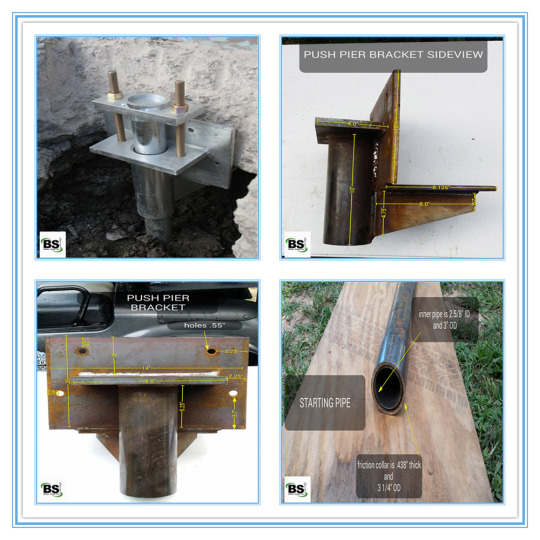
Helical Bracket
Bracket Material: ASTM A36, Made of three different thickness of plates.
Cap Plate: ASTM A572 Grade 50
Bracket Hardware: (2)-3/4”X16”Long Grade B7 All thread Rod with Nuts
All welding to be in accordance with AWS D1.1
Brackets and Caps are all available as either plain steel or Hot-dipped galvanized in accordance with ASTM A123
Bracket Hardware is provided as Electro-zinc plated in accordance with ASTM B633
0 notes
Text
Helical Bracket
Bracket Material: ASTM A36, Made of three different thickness of plates.
Cap Plate: ASTM A572 Grade 50
Bracket Hardware: (2)-3/4”X16”Long Grade B7 All thread Rod with Nuts
All welding to be in accordance with AWS D1.1
Brackets and Caps are all available as either plain steel or Hot-dipped galvanized in accordance with ASTM A123
Bracket Hardware is provided as Electro-zinc plated in accordance with ASTM B633
0 notes
Photo

Steel Thread rod with DIN ISO standard
Click here to see more of this product
#Steel Thread rod#Threaded rod DIN ISO standard#stainless steel threaded rod#m6 threaded rod#m16 threaded rod#m4 threaded rod#m5 threaded rod#12mm threaded rod#m3 threaded rod#m20 threaded bar#galvanized threaded rod#b7 threaded rod#m8 rod#ss threaded rod#a36 threaded rod#m2 threaded rod#m16 threaded bar#threaded rod m10#fully threaded rod#threaded rod m8#high tensile threaded bar#m14 threaded bar#black oxide threaded rod#galvanised threaded bar#threaded rod material#m24 stainless steel threaded bar#threaded bar m12#m24 zinc plated threaded bar
0 notes
Text
Helical Brackets
Bracket Material: ASTM A36, Made of three different thickness of plates.
Cap Plate: ASTM A572 Grade 50.
Bracket Hardware: (2)-3/4”X16”Long Grade B7 All thread Rod with Nuts.
All welding to be in accordance with AWS D1.1.
Brackets and Caps are all available as either plain steel or Hot-dipped galvanized in accordance with ASTM A153.
Bracket Hardware is provided as Electro-zinc plated in accordance with ASTM B633.
Notes: OEM service is available, different materials and specifications can be customized according to your demands.
0 notes
Text
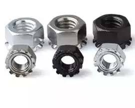
What is the use of a star washer?
The star washers are meant to boost locking force by resisting nut torque and preventing the nut from unscrewing or splitting. There are many star washer manufacturers in India, among which you should choose the best. Star washers include either internal or external tabs, allowing them to be used in a broader range of applications. In contrast, outer tabs run along the outside diameter, giving superior locking capabilities and making them excellent for applications requiring constant reliability.
Know about stainless steel dowel pins
A stainless steel dowel pins manufacturer cuts the cylindrical rods dowels into a shorter length known as a pin, often fashioned from wood, metal, or plastic. Externally threaded dowel pins are commonly employed in a variety of other applications as structural reinforcements.
There are no moving or actuating components in Grade 303 Stainless Steel Dowel Pins. The stainless steel lock nut can help you to increase the strength of your alloy. The properties of the Stainless Steel Extractable Dowel Pins are derived from the high coefficient of friction. You can also use other adhesives if you want to increase the strength.
Know about the stiffness of the stainless steel dowel pins.
The Stainless Steel Threaded Dowel Pins' stiffness allows them to keep assembled parts aligned without needing metal attaching later. You should also know about Astm a453 grade 660 as they are also solid. For a secure fit, the hole you make for them should be either the same size as the hole you made for them or slightly smaller.
The Stainless Steel Imperial Dowel Pins and grade 8 hex bolts could be used as movable game pieces or pegs; furniture shelf supports or wheel axles in toys, hooks for apparel, keyrings, tools, etc. detents in gymnastics grips. Slotted, tapered, or grooved Grade 316 Stainless Steel Dowel Pins are available.
What are Grade 660 ASTM A453 alloys?
THE SPECIFICATION OF the ASTM f593 bolts is for studs, bolts, nuts, and other fasteners used in high-temperature bolting operations. The ASTM A453 Grade 660 is divided into four property classes each having its own set of tensile and stress rupture qualities. The 12.9 Grade Allen Bolt is excellent for installing in tight locations where standard wrenches are ineffective.
Grade 660 fasteners are utilized in the bolting of high-temperature boilers, pressure tanks, pipeline flanges, and valves. ASTM A453 Grade 660 stainless steel alloys, also known as alloy A286 and UNS S66286, are chemically identical to ASTM B638 grade 660 stainless steel alloys, heat-treated to attain qualities stated in ASTM A453 specification. The material is corrosion-resistant and can withstand temperatures of up to 889 degrees Celsius due to the combination.
Properties of ASTM A36
ASTM A36 bolts specify structural carbon steel forms' chemical and mechanical properties and offer general structural applications. ASTM A36 is hot-rolled and mild steel robust, flexible, and easily machinable, making it one of the most popular steel forms in widespread use. So be wise while choosing the steel alloys for more strength.
0 notes
Text
Special Design of Heavy Mass Base Foundations Methods in Rocks and Clay Soil Sub-Surfaces Techniques

Abstract
These paper constitute consists of parts of foundations design of under and sub structural plans. First of all, foundations are the lowest artificially prepared parts of the structures which are in direct contact with ground surfaces are known as Foundations. But its different categories for the zones of ground ability. Most of the foundations are normal status and load distribution neutralizations in normal bearing values of depends upon the soils. But rocks and clay soil zones areas not suited for normal sub structural design methods. Its followed by high precious design sections and execute the better results. And followed design methods is used for high precious focus in mountain and steep constructions, Water-bearing area, it's also better suitable in heavy constructions mass base foundation methods of high rise buildings system.
Keywords: Rock boring; Grout hole; Anchorage bolting systems; Mass base trapezoidal foundations designs
Introduction
The soil ground on which the foundation's rest is that foundation bed or foundation soil and it ultimate bearing of loads and interact with the foundations of structure [1]. Case study and objective of foundations to distribute the total load coming on the structure on a large area as well as great supported on the structure and required enough stability of the structures against various disturbing forces such eradicated climatic barriers. And to prepare the level of surfaces for concreting and masonry work. Inspections of sites its desirable to recognize the site of works and inspect them carefully from the viewpoints of foundation details [2]. And to analyse the nature and thickness of strata of soil may be estimated by studying the excavation detail of nearby constructionor by examining the open side of a nearby well etc. the general inspection of site of works serves of a good guide for determining the type of foundation to be adopted for the proposed work and in addition, it helps in getting the data with respects to used for design purposes. That following data is used for items. The behaviour of ground due to variation in depth of water table, Capacity of percolation of storm water at the site, nature of the soil and visual analyzation, movement of ground due to any reason [3]. Examinations of grounds, The load of the structure is ultimately transferred to the soil it becomes, therefore, essential to know the quality and thickness of soil undergrounds and such as a study would assist in selecting an economical but safe design for the foundation of the structure [4].
Methods
That Figure 1& 2 represents the special form of trapezoidal foundation mass basements and deep grout anchorage systems. Its, essentially high interlock grip effect with substructures to superstructures. Its typically handled in 50mm deep boreholes and required depth essentially carrying out of deep boring for big important engineering structure [5]. Its methods anchor bolts rock concrete grout such as the addition to the of the ability of superstructure, importance is to be given to various other factors such as the same application in dams. Boring is followed by the 2-methods, Percussions boring machines and core rotary equipment.
In this process, the heavy cutting tool is dropped into the ground by means of a series of blows. That method used to prefer in a semi layer hard rock soil and rock layer zones areas. The broken rock material is brought to the ground by adding water into the core and then the paste is lifted to the ground. The material thus obtained is made dry and it is then examined. The percolations of boring machines is very much use of hard rock zones areas [6], And another condition it is very old method better results values and created a large number of vibrations in heavy blowing. Some problems cracking in nearest structures.
Core and rotary drilling machines
In this process, a hollow tube is driven by rotary motion which cuts a solid core. Water is used to facilitate the cutting process [7], That machines can be used either for soft or hard rocks materials. If the tube passes through a hard material, the core is retained and this has to be cut at the bottom and lifted up [8], This is done by pouring sand at the inner side between the core and inner surface of the tube and then the tube is slightly rotated [9], The core is then broken and caught in the tube along with sand and it is lifted up.
Anchorage bolts and concrete systems assembly
After the 25 to 50mm boreholes and provided the bolting anchorage rods used in the rock in required foundations depths [10], And its mostly used in peikko anchorage systems in better in rock foundation methods. At one head of fixed bolt head into the provided in required depth of rock. And after pouring the settling concrete. And setting properly and to tighten the top of the bolting rod. Its better frictions joints of the basement and foundations to substructures levels [10]. Referred the design approach of followed in ASTM, A36, A307 (Grade B), A325, A449 and A687 [11]. Used in concrete. The Bolt threads at the surrounded closing stages of apiece threaded steel bar are stake at top and bottom places below the grave curse nut. That concrete is placed in well-hardened status in 14- days after to tightening to bolt rotation.
Rock grouting
Boreholes in sufficient number are driven in the ground. The concrete grout is then forced under pressure through these bore holes [12]. These any of crack fissures of the rock are thus filled up, resulting in the increased of bearing power of rock. Its process aided to some other chemical treatment certain chemicals are used in place of cement grout to solidify the but this process is adopted by small-scale construction is costly it is only in case of important building.
Figure 3 & 4 Represents the Mass Trapezoidal basement foundations on clay and clayey soils. Clay and clayey soil is a partial work in cohesive and cohesive less in seasonal climatic conditions [13]. It is highly preferred in irrigations systems and not preferred in shallow foundations. That foundation is broadly shallow spread over the construction site area. Its possibly to constructed foundations are termed trapezoidal basement foundation. In such spread case of overall in a raft. And to assemble the assembly structural column sections. Its high economical evaluation in compared to other pile foundations better load transparent in cohesive soils.
Design criteria of special mass basement footing
The total load to be transmitted by the walls or columns to the foundation beds. The results of foundation pits and the corresponding bearing capacity of each stratum of soil [14]. It respects to 2 aspects.
Width of foundations
A width of the special footing basement is decided by adopting the following rules:
If no footing is to be provided to the constructional site area, it will provide the assumption columns should be provided in required depth and equal areas as shown in Figure 1. The total load including dead load and wind load coming on the columns per meter length at are in case of heavy construction the load aspects in the centre of the basement, it worked out. Then the width of the foundation is obtained from the following relation.
a. For column,
The width of foundation basement = {Total load per meter length /allowable bearing capacity of the soil}
b. For piers,
The width of foundations basement = {Total load on the pier/allowable bearing capacity of the soil}
Usually, the wall, columns, piers are given with of basements connects to plinth level. By adding the width of offset of concrete, the total width of foundation can be obtained. And this width of increased bearing pressure is vice versa to increase Table 1.
Depth of foundations
As a general rule, all the heavy mass base foundation should be taken to a minimum depth of 80 cm below natural ground level unless the hard soil is available within 80 cm. the total load is transferred to the soil per square meter can be worked out and after the study of the results of the trial pits, the foundation should be taken to such a depth at which the soil has an allowable bearing capacity greater than the value. The depth of foundations can also be obtained by drawing the lines of angles 450 and 600 as shown in Table 2. Rafting methods are increased the bearing power of soil becomes very useful when the load coming on the soil is practically uniform while soil yielding nature.
Conclusion
It is a final conclusion of the paper is special mass base heavy foundation technique is followed by critical soil and Rock category suitable preferred of the important structure. Such structure has to be designed for heavy loads and ordinary methods of providing foundations may not be suitable for structure. In that such case, methods handling in special heavy basement footings is resisted to heavy loads and increased the bearing capacity pressure of soil. That concept of a method of increasing the bearing power of clayey soil becomes useful, especially when there is used in a ground floor structure.
To Know More About Trends in Technical and ScientificResearch Please click on: https://juniperpublishers.com/ttsr/index.php
To Know More About Open Access Journals Please click on: https://juniperpublishers.com/index.php
#Juniper Publishers#Open acess journals#Peer review Journals#Juniper publisher reviews#Juniper Publisher journals
0 notes
Text
New AD/CVD Petitions – Carbon and Alloy Steel Threaded Rod from China, Thailand, India, and Taiwan
Vulcan Steel Products Inc. (Petitioner) on February 19, 2019, filed antidumping (AD) and countervailing duty (CVD) petitions against Carbon and Alloy Steel Threaded Rod (“Steel Threaded Rod”) from China, India, Taiwan and Thailand.
Under U.S. trade laws, a domestic industry can petition the U.S. Department of Commerce (“DOC”) and U.S. International Trade Commission (“ITC”) to investigate whether the named subject imports are being sold to the United States at less than fair value (“dumping”) or benefit from unfair government subsidies. For AD/CVD duties to be imposed, the U.S. government must determine not only that dumping or subsidization is occurring, but also that the subject imports are causing “material injury” or “threat of material injury” to the domestic industry.
— Scope
The proposed scope definition in the petition identifies the merchandise to be covered by these AD investigations as:
The merchandise covered by the scope of these investigations is carbon and alloy steel threaded rod. Steel threaded rod is certain threaded rod, bar, or studs, of carbon or alloy steel, having a solid, circular cross section of any diameter, in any straight length. Steel threaded rod is normally drawn, cold-rolled, threaded, and straightened, or it may be hot-rolled. In addition, the steel threaded rod, bar, or studs subject to these investigations are non-headed and threaded along greater than 25 percent of their total actual length. A variety of finishes or coatings, such as plain oil finish as a temporary rust protectant, zinc coating (i.e., galvanized, whether by electroplating or hot-dipping), paint, and other similar finishes and coatings, may be applied to the merchandise.
Steel threaded rod is normally produced to American Society for Testing and Materials (“ASTM”) specifications ASTM A36, ASTM A193 B7/B7m, ASTM A193 B16, ASTM A307, ASTM A320 L7/L7M, ASTM A320 L43, ASTM A354 BC and BD, ASTM A449, ASTM F1554-36, ASTM F1554-55, ASTM F1554 Grade 105, American Society of Mechanical Engineers (“ASME”) specification ASME B18.31.3, and American Petroleum Institute (“API”) specification API 20E. All steel threaded rod meeting the physical description set forth above is covered by the scope of these investigations, whether or not produced according to a particular standard.
Subject merchandise includes material matching the above description that has been finished, assembled, or packaged in a third country, including by cutting, chamfering, coating, or painting the threaded rod, by attaching the threaded rod to, or packaging it with, another product, or any other finishing, assembly, or packaging operation that would not otherwise remove the merchandise from the scope of the investigation if performed in the country of manufacture of the threaded rod.
Carbon and alloy steel threaded rod are also included in the scope of this investigation whether or not imported attached to, or in conjunction with, other parts and accessories such as nuts and washers. If carbon and alloy steel threaded rod are imported attached to, or in conjunction with, such non-subject merchandise, only the threaded rod is included in the scope.
Excluded from the scope of these investigations are: (1) threaded rod, bar, or studs which are threaded only on one or both ends and the threading covers 25 percent or less of the total actual length; and (2) stainless steel threaded rod, defined as steel threaded rod containing, by weight,1.2 percent or less of carbon and 10.5 percent or more of chromium, with or without other elements.
Excluded from the scope of the antidumping investigation on steel threaded rod from the People’s Republic of China is any merchandise covered by the existing antidumping order on Certain Steel Threaded Rod from the People’s Republic of China. See Certain Steel Threaded Rod from the People’s Republic of China: Notice of Antidumping Duty Order, 74 Fed. Reg. 17,154 (Dep’t Commerce Apr. 14, 2009).
Steel threaded rod is currently classifiable under subheadings 7318.15.5051, 7318.15.5056, and 7318.15.5090 of the Harmonized Tariff Schedule of the United States (“HTSUS”). Subject merchandise may also enter under subheading 7318.15.2095 and 7318.19.0000 of the HTSUS. The HTSUS subheadings are provided for convenience and U.S. Customs purposes only. The written description of the scope is dispositive.
— Alleged AD Margins.
Petitioner calculated estimated dumping margins of:
China: 53.57% to 55.60% India: 25.43% to 28.34% Taiwan: 32.10% Thailand: Not Yet Available
— Named Exporters/ Producers
Petitioner included a list of companies that it believes are producers and exporters of the subject merchandise. See attached list here.
— Named U.S. Importers
Petitioner included a list of companies that it believes are U.S. importers of the subject merchandise. See attached list here.
— Estimated Schedule of Investigations.
February 21, 2019 – Petitions filed
March 13, 2019 – DOC initiates investigation
March 14, 2019 – ITC Staff Conference
April 7, 2019 – ITC preliminary determination
July 21, 2019 – DOC CVD preliminary determination (assuming extended deadline)
September 19, 2019 – DOC AD preliminary determination (assuming extended deadline)
February 1, 2020 – DOC AD/CVD final determination (assuming extended deadlines)
March 17, 2020 – ITC final determination (extended)
March 24, 2020 – DOC AD/CVD orders issued (extended)
This product has previously been subject to other AD/CVD investigations. In 2009, AD/CVD orders were imposed on carbon steel threaded rod from China. In 2013, although Petitioner tried to get AD/CVD orders imposed on carbon steel threaded rod from India and Thailand, the ITC made a negative determination (i.e, no injury or threat of injury caused by the subject imports). This Petitioner appears to be a serial user of US trade laws repeatedly trying to get the US government to issue protective duties against subject imports. Given that the Petitioner’s most recent attempt to get AD/CVD duties imposed was unsuccessful, foreign exporters or US importers of this product may be able to use similar arguments to explain why these new AD/CVD actions should also be rejected.
New AD/CVD Petitions – Carbon and Alloy Steel Threaded Rod from China, Thailand, India, and Taiwan syndicated from https://immigrationattorneyto.wordpress.com/
0 notes
Text
Building a vise - couple questions
Hi all,
I've been wanting a vise for a long time but have not been able to score any deals on craigslist or at local shops. Today I was at the local steel yard and found a chunk about 18" long of 1-1/4" x 5tpi ACME rod with some surface rust in the scrap bin. $0.50/lb, sounds good! I decided on a whim to pick up some other parts to make the remainder of the vise out of. 74lbs of steel later, I've got some decent stuff to make a really heavy duty unit.
The questions:
I need one or more matching ACME nuts for the screw. I've seen several designs online, some people use a single nut welded to the base, others line up multiple nuts and weld them all together. I'm thinking that welding multiple nuts together would pose challenges with alignment of the threads... in other words, unless you somehow preloaded all the nuts, only one of them would end up handling the majority of the load. What's the correct or best configuration?
I see most vises have a slot cut in the bottom of the movable jaw's bar that allows a 'post' to stick up, holding the leadscrew nut on the fixed base. As I understand it, the closer the leadscrew is to the jaws, the less twisting forces are applied to the whole vise. Is there a reason that the slot isn't cut in the top of the movable jaw's bar?
Should I attempt to case-harden the jaws and/or anvil and/or entire vise body? The steel I bought is A36 mild steel.
submitted by /u/cathode_01 [link] [comments]
0 notes
Photo

Steel Thread rod with DIN ISO standard
Click here to see more of this product
#Steel Threaded rod#Threaded rod with ISO standard#Threaded rod with DIN standard#stainless steel threaded rod#m6 threaded rod#m16 threaded rod#m4 threaded rod#m5 threaded rod#m3 threaded rod#m20 threaded bar#galvanized threaded rod#stainless threaded rod#b7 threaded rod#stainless steel threaded bar#m8 rod#ss threaded rod#a36 threaded rod#m16 threaded bar#m12 stainless steel threaded rod#fully threaded rod#threaded rod m8#m10 stainless steel threaded rod#high tensile threaded bar#m14 threaded bar#threaded steel bar#stainless threaded bar#m5 threaded bar#316 stainless steel threaded rod#stainless steel all thread rod#astm a307 threaded rod
0 notes
Text
FAQs Regarding Strong-Rod Anchor Tiedown Systems (ATS) for Shearwall Overturning
How would a six-story light-frame wood building perform in a large earthquake? Back in 2009, Simpson Strong-Tie was a partner in the World’s Largest Earthquake Test, a collaboration of the NEESWood project, to answer that question. This was a full-scale test which subjected the building to 180% of the Northridge earthquake ground motions (approximately a M7.5). Within the building, Simpson Strong-Tie connectors and Strong-Frame SMF were used, with the Strong-Rod™ anchor tiedown system (ATS) serving as holdown for each shearwall.
The NEESWood building was designed under Performance-Based Design methodology, and the test was conducted as validation for the approach. Buildings of similar size to the NEESWood building are built to current codes using similar products. Mid-rise light-frame wood structures continue to be a popular form of construction in various densely populated cities across the country. As part of the lateral-force-resisting system, continuous rod systems are used as the holdown for the shearwall overturning restraints. Simpson Strong-Tie has been involved with continuous rod systems since the early 2000s when we launched the Strong-Rod anchor tiedown system.
Today, rod manufacturers design the continuous rod systems with design requirements (loading, geometry, etc.) Supporting documents (e.g., installation details, layouts, RFI/markups and calculations) are submitted for each unique project. Over the years, engineers have asked many questions related to the design of these systems. In this week’s blog, we will explore Frequently Asked Questions pertaining to Strong-Rod ATS systems used as shearwall overturning restraints (holdowns).
Is there a code report for the system?
The Strong-Rod ATS system is a series of rods (fully threaded rods and proprietary Strong-Rods), coupler nuts, bearing plates, nuts and shrinkage compensation devices (ATUD/TUD and RTUD).
The majority of these components are designed in accordance with the building code and reference standards (e.g., NDS, AISC). A project-specific calculation package is submitted for each job that addresses the evaluation of these elements. Therefore, these elements are not listed in evaluation reports.
Shrinkage compensation devices, on the other hand, are proprietary components which are not addressed by the building code or reference standards. Therefore, they are tested in accordance with ICC-ES acceptance criteria AC316 and are listed in ICC-ES ESR-2320.
What is the material specification of the rods used above concrete?
The specified rod materials are shown in Table 1.
Table 1. ATS Rod Material Specifications
Can threaded rods or couplers be welded to steel beams?
Simpson Strong-Tie generally does not recommend this practice. Of the materials listed in Table 1, ASTM A307 material is the only specification that contains supplementary requirements for welding. When standard strength rod is supplied to the job, it is not guaranteed that this will be the material provided.
ASTM A449 and A193-B7 high-strength rods develop strength and ductility characteristics through controlled quenching and tempering treatments. Quenching is the rapid cooling of metal (usually by water or oil) to increase toughness and strength. This process often increases brittleness. Tempering is a controlled reheating of the metal which increases ductility after the quenching process. Precise timing in the application of temperature during the tempering process is critical to achieving a material with well-balanced mechanical properties. It is unlikely that field welding will satisfy the requirements of quenching and tempering.
Coupler nuts are generally fabricated from material exhibiting characteristics similar to high-strength rods. Thus, it is not recommended to weld coupler nuts to steel beams due to the potential for embrittlement.
Simpson Strong-Tie specifies a weldable cage which is fabricated from ASTM A36 material for such applications.
How do you calculate the Maximum ASD Tension Capacity provided in the job summary?
Simpson Strong-Tie provides a comprehensive design package for continuous rod systems used as holdowns for multi-story stacked shearwalls. The individual run calculations, as shown in Figure 1, provide the Maximum Tension Capacity, which correlates to the maximum force the system can deliver. Plan check often requests justification on how these values are derived at each level. These values are calculated, and the process explained below may be used on any Simpson Strong-Tie ATS Job Summary as justification.
Figure 1. Sample ATS Run Type SW9
The maximum tension capacity published within the Job Summary and the Installation Details is derived using the following procedure:
Step 1: Evaluate the top-most level. Compare the published capacities of the rod in tension, plate in bearing and the take-up device. The lowest of these three will govern and becomes the Maximum Tension Capacity for this level.
Step 2: Evaluate the next level down. (a) Sum the Maximum Tension Capacity from Step 1 and the published capacity of the take-up device from this level. (b) Sum the Maximum Tension Capacity from Step 1 and the published capacity of the plate in bearing from this level. (c) Compare derived values from (a) and (b) to the published capacity of rod in tension. The lowest of these three values will govern and becomes the Maximum Tension Capacity of this level.
Step 3: Repeat Step 2 as necessary until the bottom-most level is reached.
Applying this procedure to the sample run, SW9, will wield the following result:
Step 1: Evaluate capacities published at Level 4
Plate in bearing (PBRTUD5-6A) = 7.06 kips governs
Take-up device (RTUD6) = 20.83 kips
Rod in tension (ATS-R6) = 9.61 kips
The lowest value in Step 1 is the plate in bearing, hence 7.06 kips is the maximum load that can be delivered at Level 4 and is the Maximum Tension Capacity.
Step 2: Evaluate capacities at Level 3
Maximum Tension Capacity from Level 4 = 7.06 kips (See Step 1)
Maximum Tension Capacity from Level 4 + take-up device (ATS-ATUD9-2) = 7.06 + 12.79 = 19.85 kips
Maximum Tension Capacity from Level 4 + plate in bearing (PL9-3×5.5) = 7.06 + 10.03 = 17.09 kips
Rod in tension (ATS-R7) = 13.08 kips governs
The lowest value in Step 2 is the rod in tension, hence 13.08 kips is the maximum load that can be delivered at Level 3 and is the Maximum Tension Capacity.
Step 3: Evaluate capacities at Level 2
Maximum Tension Capacity from Level 3 = 13.08 kips (See Step 2)
Maximum Tension Capacity from Level 3 + take-up device (ATS-ATUD9-2) = 13.08 + 15.56 = 28.64 kips
Maximum Tension Capacity from Level 3 + plate in bearing (PL9-3×5.5) = 13.08 + 10.03 = 23.11 kips
Rod in tension (ATS-R7) = 13.08 kips governs
The lowest value in Step 3 is the rod in tension, hence 13.08 kips is the maximum load that can be delivered at Level 2 and is the Maximum Tension Capacity.
Step 4: Evaluate capacities at Level 1
Maximum Tension Capacity from Level 2 = 13.08 kips (See Step 3)
Maximum Tension Capacity from Level 2 + take-up device (ATS-ATUD14) = 13.08 + 24.39 = 37.47 kips
Maximum Tension Capacity from Level 2 + plate in bearing (PL14-3×8.5) = 13.08 + 13.98 = 27.05 kips governs
Rod in tension (ATS-R11) = 32.30 kips
The lowest value in Step 4 is due to the plate in bearing, hence 27.05 kips is the maximum load that can be delivered at Level 1 and is the Maximum Tension Capacity.
In the System Deflection Summary page(s) of the Job Summary, is the Total System Deflection provided at Allowable or Strength levels?
Immediately following the individual run calculations in each job summary, Simpson Strong-Tie provides a summary of deflection of the rod system similar to what is shown in Figure 2. This breaks down the deformation of all components being considered. In the example below, the rod elongation and deflection of the take-up device are summed to provide the total deflection.
The calculated system deflection is presented at ASD level. See section below for how to use these system deflections for your drift calculation.
Figure 2. Sample System Deflection Check
What system deflection limit do you typically design to, and what does that include?
Unless otherwise specified on the plans or required by the building jurisdiction, Simpson Strong-Tie will design the continuous rod system to satisfy the deformation limits set forth in ICC-ES Acceptance Criteria (AC316). In some instances, the Designer may need a more restrictive deformation due to project specific conditions (e.g., tight building separations) and will require rod manufacturers to design for a lower deformation. Some jurisdictions (e.g., City of San Diego, City of San Francisco) may also have specific design requirements that continuous rod systems must conform to. The minimum recommended per-floor deformation limit set forth in AC316 is:
(Rod Elongation) + (Shrinkage Compensation Device Deflection) ≤ 0.2” (ASD),
Or (PDL/AE) + [ΔR + ΔA(PD/PA)] ≤ 0.2” (ASD)
Where:
PD = ASD demand cumulative tension load (kips) L = length of the rod between restraints – i.e., floor-to-floor (in.) A = net tensile area of the rod (in.2) E = Young’s Modulus of Elasticity (29,000 ksi) ΔR = seating increment of the shrinkage compensation device (as published in ICC-ES evaluation report) ΔA = deflection of the shrinkage compensation device at the allowable load (as published in ICC-ES evaluation report) PA = Allowable capacity (kips)
Should deformation limits be specified in the construction documents?
Simpson Strong-Tie strongly recommends this information be included in the construction documents. Along with the cumulative tension and compression forces, the required deformation limits for the holdown are important to ensure that rod manufacturers are designing the holdown to satisfy the desired shearwall performance.
How do I use the system deformation limit?
The System Deflection is the total deformation of the holdown system from floor to floor (refer to the last two columns in Figure 2). This information represents the total ASD holdown deformation term, Δa, for each level and is to be used in the shearwall drift equation from the Special Design Provisions for Wind and Seismic (2015 SDPWS 4.3-1).
ASCE 12.8.6 requires that shearwall drift be calculated at strength level. Therefore, the information provided within the System Deflection Summary page needs to be converted from ASD to Strength Level. The conversion factors in Table 2 can be used to convert the ASD deformations to strength level. For discussions and methodology in converting bearing plate deformation to strength level, please refer to the WoodWorks Design Example of a Five-Story Wood Frame Structure over Podium Slab found here.
Table 2. ATS Rod Deflection ASD to LRFD Conversion Factors
Can rod systems be used in Type III construction?
Yes! 2015 IBC §2303.2.5 requires that Fire Retardant-Treated Wood (FRTW) design values be adjusted based on the type of treatment used on the project. Adjustment factors vary for each FRTW manufacturer; refer to the ICC-ES evaluation report of the specified FRTW manufacturer for the unique adjustment values. Rod manufacturers need to know what treatment is being used so this information can be taken into consideration when designing compression posts and incremental bearing (bearing plates).
For more information and previous discussions on fire protection in mid-rise construction, see our previous posts: Fire Protection Considerations with Five-Story Wood-Frame Buildings Part 1 and Part 2, and Connectors and Fasteners in Fire-Retardant-Treated Wood.
What are Simpson Strong-Tie’s guidelines for fire caulking material?
While there are many options for fire-rated caulking, these products can be used in conjunction with the Simpson Strong-Tie ATS system. Below is a list of considerations when selecting and specifying a material for use where the rods penetrate the top and sole plates:
The fire-rated caulking shall not be corrosive to metal when used in contact with ATS components.
Direct contact with shrinkage compensating devices (e.g., TUD, ATUD, RTUD) shall be avoided. Shrinkage compensating devices have moving components and may not function properly with debris interference.
Indirect contact with shrinkage compensating devices shall also be avoided. Shrinkage compensation accumulates up the building and therefore the largest shrinkage occurs at the top of the building. As such, when the building shrinks, remnants of the material may still be stuck to the threads of the rod and may be detrimental to the performance of some shrinkage compensating devices (e.g., an RTUD). It is recommended to detail the installation with shrinkage taken into consideration.
The fire-rated caulking should be pliable to accommodate wood shrinkage and the building moving down during this process.
The performance and the suitability of fire-rated caulking are outside the scope of Simpson Strong-Tie.
Why doesn’t your design include compression post design?
If the Engineer of Record has already specified compression posts to be used with a continuous rod system, Simpson Strong-Tie will not provide these on the holdown installation drawings. This is primarily done to prevent discrepancies between the specification in the contract documents and what is shown on the installation drawings.
What is the maximum spacing between compression posts?
For platform-framed structures, the maximum spacing between compression posts is 9″. The large majority of Simpson Strong-Tie bearing plates will fit within the 9″ spacing requirement, eliminating the need for notching compression posts. In some framing conditions, such as balloon framing or a top chord bearing truss, the maximum spacing will be reduced to 6″. This is due to the limited amount of space between the top of the compression posts transferring uplift (via bearing) into the point of restraint (e.g., bearing plate) at the level above. To ensure this load path is complete, the posts need to be spaced closer.
What is the nailing schedule for the bridge block to the king studs?
Simpson Strong-Tie doesn’t recommend nailing the bridge block to the cripple as the bridge block member will shrink. Locking the bridge block in place may result in a gap forming between the bottom of the bridge block member and the top of the cripple studs, which is not accounted for in the Total System Deflection.
Are there any published documents with design examples of continuous rod systems used in mid-rise construction?
There are two resources publicly available that provide discussion and examples. The first is a manual published by the Structural Engineers Association of California (SEAOC). Titled 2015 IBC SEAOC Structural/Seismic Design Manual Volume 2 – Examples for Light-Frame, Tilt-Up and Masonry Buildings, this document provides two examples – one for a four-story wood hotel building, and the other for a three-story cold-formed steel apartment building on concrete podium deck.
Another useful resource is published by WoodWorks and is a design example of a five-story wood-frame structure over podium slab. This document can be found here.
What questions do you have about the Strong-Rod ATS System? Leave them below.
The post FAQs Regarding Strong-Rod Anchor Tiedown Systems (ATS) for Shearwall Overturning appeared first on Simpson Strong-Tie Structural Engineering Blog.
from Simpson Strong-Tie Structural Engineering Blog http://ift.tt/2oO4g6g
FAQs Regarding Strong-Rod Anchor Tiedown Systems (ATS) for Shearwall Overturning published first on your-t1-blog-url
0 notes
Photo

ASTM a193 b7 threaded rod bolt All Threaded Rod UNC UNF
click here to see more of this product
#ASTM threaded rod bolt#ASTM threaded rod#b7 threaded rod#a193 threaded rod#Threaded Rod UNC#Threaded Rod UNF#astm a307 galvanized bolts#a307 threaded rod#Hex bolts#astm a193 grade b7 threaded rod#astm a307 bolt properties#weldable threaded rod#astm a325 threaded rod#astm a354bd threaded rod#astm a325 all thread#astm a307 threaded rod#threaded rod grades#threaded rod color code chart#a36 threaded rod#Threaded rods#grade 55 threaded rod#b7 threaded rod portland bolt#b7 threaded rod spec sheet#b7 threaded rod load capacity#58 b7 threaded rod#34 b7 threaded rod#b7 threaded rod fastenal#grade b7#b7 threaded rod specs#b7 threaded rod torque specs
0 notes