#chamfer ring
Explore tagged Tumblr posts
Visit Tumblr Blog
Explore Tumblr blogs with no restrictions, modern design and the best experience.
Last Seen Tumblr Blogs


Fun Fact
Tumblr has been banned in Indonesia for providing people with access to pornographic content.

Text
Leather Coat Strider inspired by the Aragorn's duster (LOTR)
The “Strider” coat is a leather coat based on Aragorn’s duster from the Lord of the Rings trilogy. We used our replica patterns, but this time we chose slightly more glossy and textured Italian leather. All allowances of the main seams were chamfered so as not to give extra volume and not to spoil the appearance. This model is a transformer product (vest, camisole, tabard and duster), which…
#aragorn#aragorn coat#aragorn cosplay#aragorn costume#cosplay#geek#handmade#LARP#leather#leather goods#LOTR#lotr cosplay#lotr fan#SvetliySudarWorkshop
4 notes
·
View notes
Text

Locked to the strip. The NW105 5-Lug Beadlock wheel is very similar to our original NW105 5-Lug one piece forged monoblock wheel with one big exception: It has been re-engineered to include a special bolt-on outboard beadlock ring that, like the wheel itself, is also precision-machined from forged 6061-T6 aluminum. This forged aluminum ring holds the tire securely in place, to limit unwanted tire slip against the wheel, and to keep the tire from unseating, at very high speeds. The forged beadlock ring is secured to the wheel with a series of 21 standard lightweight titanium bolts. The Forgeline forged monoblock NW105 5-Lug Beadlock features a split 7-spoke design with tapered angular spokes and pronounced chamfered edges that creates a high-tech appearance on par with its advanced engineering technology and standard-setting performance capability. It is is available to order immediately in 17-inch, 18-inch, and 19-inch diameters in a range of widths and custom offsets & fitments. And just like any Forgeline wheel, the NW105 5-Lug Beadlock is available with fully customizable finish options. Learn more (including sizes and pricing) at: https://forgeline.com/wheel/nw105-5-lug-beadlock
🇺🇸🇺🇸🇺🇸
#forgeline#forgelinewheels#forgedwheels#customwheels#forgedmonoblock#NW1055LugBeadlock#ForgelineNW1055LugBeadlock#beadlock#dragracing#notjustanotherprettywheel#doyourhomework#madeinUSA#PRIShow#PRI2023
8 notes
·
View notes
Text
What is the Best Selling Precast Concrete Product?
When it comes to the construction industry, precast concrete products have revolutionized modern building practices. Offering unmatched durability, consistency, and speed of installation, these products are in high demand across various sectors. However, among the wide range of options available, one product consistently outperforms others in terms of sales volume, demand, and utility: precast concrete manholes.
Why Precast Concrete Manholes Dominate the Market
Precast concrete manholes are the backbone of underground infrastructure. Used extensively in municipal, industrial, and residential projects, they form critical components in stormwater systems, sewer systems, telecommunications, and electrical utilities.
Their massive demand is driven by ongoing urban development, infrastructure upgrades, and their adaptability across numerous applications. Contractors and civil engineers prefer precast manholes due to their uniform quality, time-saving installation, and resistance to corrosion and environmental damage.
Key Features that Make Precast Concrete Manholes a Top Seller
High Structural Strength: Engineered to withstand high loads and pressure, making them ideal for both light-duty and heavy-traffic areas.
Precision Manufacturing: Produced in controlled environments, ensuring consistent quality, smooth finishes, and accurate dimensions.
Customizable Design: Available in a variety of shapes, sizes, and configurations, including risers, grade rings, eccentric cones, and flat tops.
Quick Installation: Delivered ready-to-install, reducing on-site labor and associated costs.
Sustainability: Long service life and made from locally available materials with minimal waste generation.
Other High-Selling Precast Concrete Products
While manholes lead the pack, the following products are also among the most commercially successful:
1. Precast Paver Stone Pathways
Paver stones are widely used in landscaping, residential developments, and public spaces. These modular, aesthetically pleasing stones are engineered to create durable, low-maintenance walkways, driveways, patios, and plazas.
Benefits Include:
Superior visual appeal with a variety of textures and colors
High load-bearing capacity, suitable for both pedestrian and light vehicular traffic
Permeable options available for effective stormwater management
Easy maintenance and replacement of individual units
Paver stones not only enhance curb appeal but also offer long-lasting durability and a customizable solution for modern outdoor environments.
2. Precast Concrete Walls Panels
From highway embankments to landscape architecture, retaining walls are a staple in projects requiring earth retention and aesthetic boundary solutions.
Key Features:
Modular construction
Reduced excavation needs
Consistent architectural finish
3. Precast Wall Coping Stones
Wall coping stones are another high-demand product used to cap the tops of masonry or precast walls, protecting them from weather damage while providing a polished architectural finish.
Notable Advantages:
Prevent water ingress and structural deterioration of walls
Available in various styles, including flat, sloped, and chamfered edges
Enhance the visual continuity of fences, retaining walls, and parapets
Quick installation with consistent finishes
Wall coping stones are a critical finishing component in residential, commercial, and civic architecture, offering both functional integrity and elevated design appeal.
4. Precast Concrete Stair Treads
In residential and commercial buildings, precast stair units offer a practical solution for quick installation without sacrificing design or safety.
Top Benefits:
Slip-resistant surfaces
Fire-resistant materials
Ready-to-finish surfaces
Why Precast Products Are Becoming the Industry Standard
Modern construction demands materials that are cost-effective, reliable, and compliant with strict quality standards. Precast concrete products meet all these expectations and offer the added advantage of reducing construction timelines, which directly translates into lower project costs.
The move towards prefabrication and modular construction continues to accelerate the demand for precast elements across both private and public sector projects.
Innovations in Precast Manufacturing Driving Sales
The precast concrete industry is no longer limited to traditional shapes and uses. Advancements such as:
Self-healing concrete
Fiber-reinforced concrete
Embedded smart sensors
…are enhancing the functionality and appeal of precast products, attracting more contractors and infrastructure developers.
Moreover, 3D formwork systems and automated reinforcement placement are pushing the limits of customization and precision, allowing manufacturers to deliver tailored solutions at scale—another reason why products like precast manholes continue to dominate the market.
Choosing the Right Precast Supplier Matters
Given the widespread use and importance of precast concrete products, partnering with a reputable precast manufacturer is essential. The best suppliers offer:
Comprehensive product catalogs
Certified quality assurance
On-time delivery capabilities
Technical support and design assistance
These factors ensure that projects proceed smoothly and that the products perform reliably for decades.
Conclusion: Precast Concrete Manholes Reign Supreme
When analyzing sales performance, market demand, and application diversity, precast concrete manholes emerge as the best selling precast concrete product. Their versatility, engineering reliability, and widespread adoption across sectors make them an indispensable element in modern infrastructure.
#Precast Paver Stone Pathways#Precast Wall Coping Stones#Precast Concrete Walls Panels#Precast Concrete Stair Treads
0 notes
Text
Cooler Master Mobius 120P ARGB Radiator Fan White Edition - Ring Blade Design (PWM), Loop Dynamic Bearing System (max. 75.2 CFM, 3.63 mmH2O, 30 dBA), Chamfered Air-Focus Frame - Addressable Gen 2 RGB
Price: (as of – Details) Cooler Master Mobius 140P ARGB is a new cooling fan designed with radiator cooling performance and acoustics in mind. Featuring an advanced ring fan blade design, the Mobius 140P generates minimal noise (max. 30 dBA) with maximum airflow (76.5 CFM, 2.3 mmH2O). Anti-vibration dampers ensure a stable, silent performance by reducing vibration & rattling. An angled inner…
0 notes
Text
Louis Erard once again joins hands with independent watchmaker Vianney Halter to launch a new joint watch - Régulateur Louis Erard x Vianney Halter Chapter II
Louis Erard has once again joined hands with Vianney Halter, the master of independent watchmaking, to present a new co-branded watch, the Régulateur Louis Erard x Vianney Halter Chapter II. The limited edition of 178 pieces continues the aesthetics of Steam Pang and incorporates more symbolic design language, and is another innovative result of the collaboration between the brand and the watchmaker.

Since the brand's inception, Louis Erard has continued to expand its portfolio of special editions through collaborations with watchmakers and designers. Collaborations with Kudoke, Alain Silberstein, Cédric Johner and Massena LAB are among the brand's innovative expressions in design and craftsmanship. This is the second collaboration between Louis Erard and Vianney Halter, and Sensei inherits Halter's classic Antiqua design style, with more modern elements. Régulateur Louis Erard x Vianney Halter II combines the design language of Steam Ponk with the classic watchmaking process to reinterpret the traditional Régulateur three-point line, revealing Halter's emphasis on detail and its unique design qualities.
With steam pneumonics at its core, the new watch combines ancient futurism and deconstructive aesthetics to show a double charm. With a diameter of 43 mm and a thickness of 10.95 mm, the case adopts a three-piece structure of stainless steel, with polishing and haze hair texture to create a rich and delicate appearance. The watch ring is adorned with 12 rose gold polished hammers, which are designed with a striking steam punk character and structural beauty. The crown shifted to 2 o'clock is inlaid with a rose gold hammer, which echoes the inclined layout of the movement and the language of the bezel design. The curved lugs are ergonomically designed for comfort and stability, and the lugs are spaced at 49.6 mm for a more elegant and sleek shape.
The design of the watch is ingenious, with a pen-type blue steel indicator for the central disc, an eccentric hour at 11 o'clock and a small seconds at 5 o'clock. Through a special inclined layout, an asymmetrical dynamic aesthetic is revealed. The minute scale ring is designed with raised design, with Louis Erard and Vianney Haller logos and red gold or bronze rings for added depth and visual tension. The ring is round-strapped and diamond-cut chamfered and dotted with black transcribing scales to highlight the fine craftsmanship of watchmaking. Depending on the version, the watch base is available in either a red and gold or a gold and gold color scheme, with the retail model being a red gold base with a gold trim ring, while the brand's official website model is reversed with a gold and red gold trim ring.

The watch lens is made of double-sided anti-glare bluestone crystal glass for clear vision and exceptional durability. The strap is made of dark brown grained calfskin, with a tonal sewing cable and a black inner sleeve for both comfort and elegance, and a quick-release design allows the wearer to easily change the strap to meet the needs of personalization. The overall design strikes a perfect balance between the ancient and the modern, and the dual value of design and craftsmanship can be felt, whether worn for everyday wear or collectible.
This watch is equipped with a Sellita SW266-1 self-winding movement, which oscillates 28,800 vibrations per hour and has a power storage of about 38 hours, making it stable and reliable for daily use. The transparent backing showcases a special Hollow Automator Wheel, which is inspired by the Louis Erard logo and features 5N rose gold electro-silver craftsmanship in a meticulous design that fully demonstrates the brand's pursuit of the art of watchmaking.
This imitation watches is water-resistant to 50 metres, making it ideal for everyday use. The dark brown grained calfskin strap is not only equipped with a quick-release design, but also comes with a stainless steel buckle for a flexible and comfortable fit. Limited to 178 pieces, each with a limited edition number, this co-branded watch showcases the high degree of integration between design and technology, as well as the brand's and master's profound interpretation of the concept of "Endless Prosperity and Prosperity".
The second collaboration between Louis Erard and Vianney Hater combines the two parties' quests for watchmaking aesthetics and craftsmanship to further explore the possibilities of revival, futurism and modern design. With its limited edition and unique design, the Régulateur Louis Erard x Vianney Halter II embodies the creative spark sparked by the collaboration between the brand and the masters.
0 notes
Text
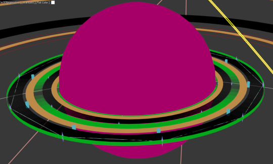
Creating the Milky Way and Sesaris Paired Birch World Complexes part 3
after the Alderson Discs I figured out how to make the Ringworlds and got started on them although I basically just started working from the middle outwards


first group of Ringworlds
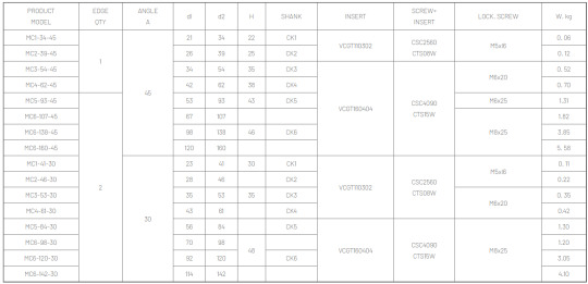
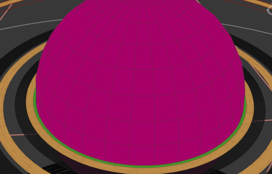
the way I made Ringworlds was by making a torus with R1 of the radius of the ring and R2 of 0.001 then I would elongate the z scale up to create the vertical height

first group of habitats
the way I made the habitats was by taking a cylinder with 10 height segments (12 if it was particularly tall) then converting to editable polly, collapsing the top and bottom edge loops into points and then going through and scaling the other edge loops until they looked good then chamfering them all to create a smooth curve

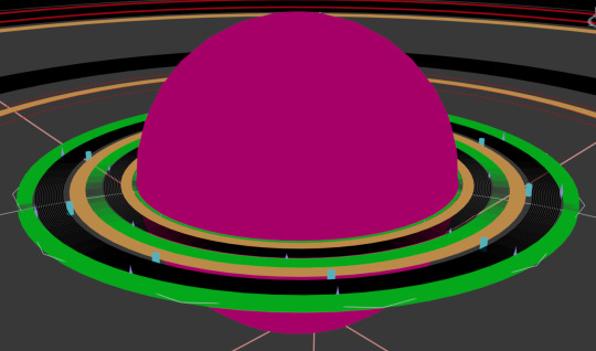
group 2 of Habitats and Ringworlds
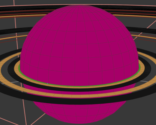
first lot of Farming Disc stacks and starting group 3 habitats
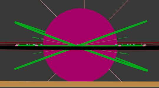
the angular shape coming off the habitat is my refence shape, it was a torus that I set to a segment count equivelant to the number of habitats or whatever in a group so I could place them on the corners to get an accurate 10 or 12 or 16 or however many neatly arranged habitats or whatever
those group 3 habitats done, you can see how my reference shape goes between the corners
third group of ringworlds

adding the first lot of little Birch Worlds to the structure


fourth group of Ringworlds, this is where I get to the first tilted structures, technically it should've happened before but I forgot to tilt those until now
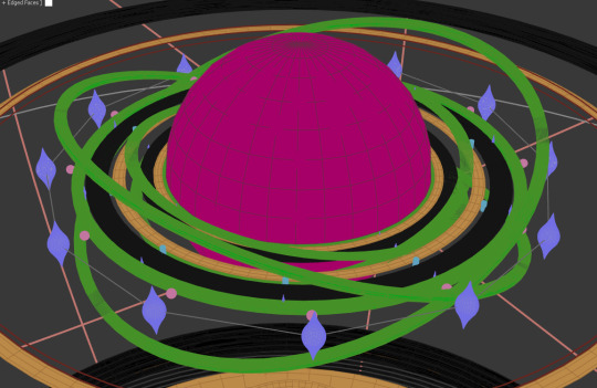
group 4 Habitats
0 notes
Text
The First Project Part 3 (Unwrapping)

We're creating smooth edges and hard edges. The hubcap's seams should be hard, but the outer ring of it should be smooth.
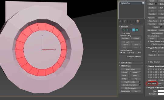
Select the ring, then auto smooth.

I've smoothed the other ring too, then i hardened the edges between the tire and the final ring.
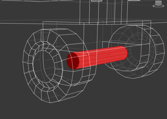
Select an object a part of the whole plane, then go into F3 to kind of isolate it. I'm just checking I've beheaded the cylinders.
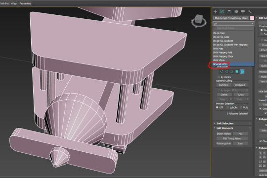

Applied the UVW unwrap modifier.
Ctrl A, select all faces

2. Flatten Mapping.
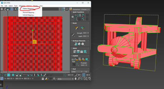
3. Slarp ok button.
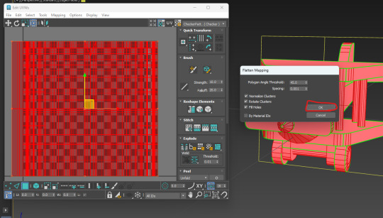
Now we have some edge, face, and vertex select for this screen separate from the main 3ds editor.
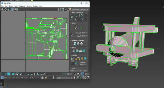
Moving the UVs out of the area.

Now select the tail fin in the main 3ds and that will select it's islands in the UV editor. I drag them out of the main cluster.

Click the edge of this chamfer, then click stich custom.

That will stich the disconnected parts back together as they connect on the model itself.
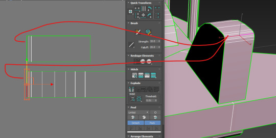
As you can see here, these two edges connect on the model, but are disconnected in the UV unwrap. This is why I will use the custom stich tool, to bring these back together.
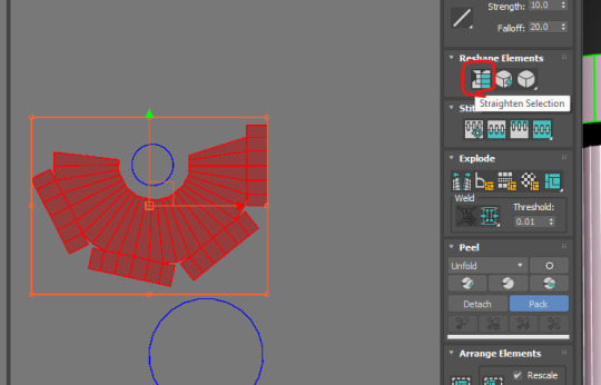
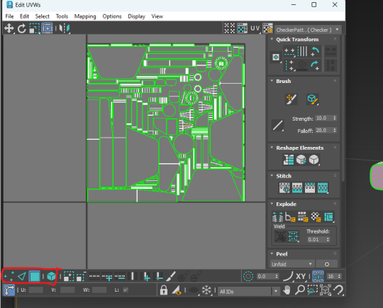
After connecting the cone's edges click straighten selection (I've been doing the simple connections for the rest of the things).

actually don't do that last step that will fuck shit up. Instead break off these bits using the break tool, then flatten the skirt, then re-stitch the stuff back to it.
the result.

Disconnect the hub from the wheel.

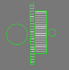
for the smaller bits, select their origin (the outer ring), hen click quick planar map to connect them up.
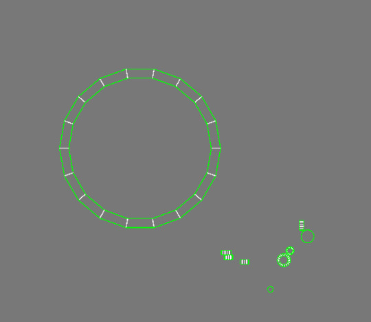
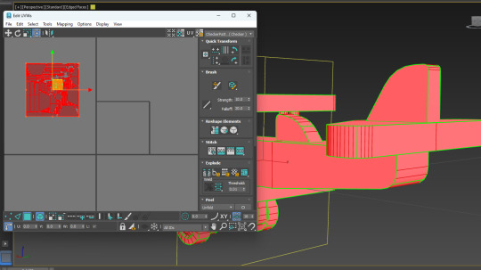
I'll get this giant circle, but the size doesn't really matter.
For packing to ensure maximum space is used I must break some parts into smaller pieces:

These long pieces can be split near the middle using the break tool, these are the seams I'm splitting. There's some wasted space in that top right area.
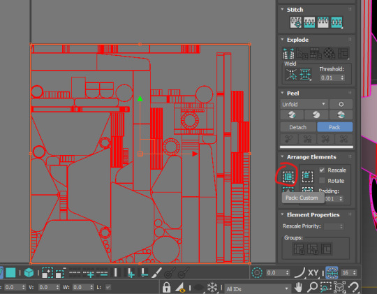
Now I repack the whole thing (I forgot to document packing, but basically you just ctrl+a all the islands then click pack custom).

Now you can see some of the wasted space is reduced, though it might be required to cut down on some more pieces to squeeze a little more space, maybe not though.
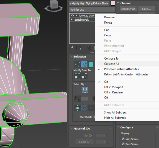
Now we right click on unwrap UVW and collapse all.
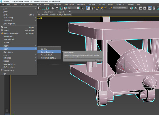
export.
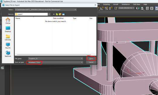
sexport.

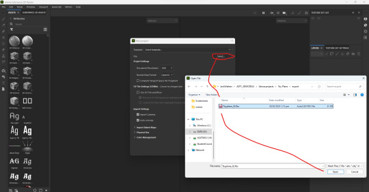
Going to Substance painter
0 notes
Text
Finishing Touches
For the last few modeled parts, I thought I'd pull them all together, since they are rather short 'n sweet.
..............................................................................................................................
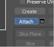
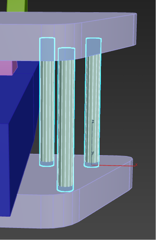
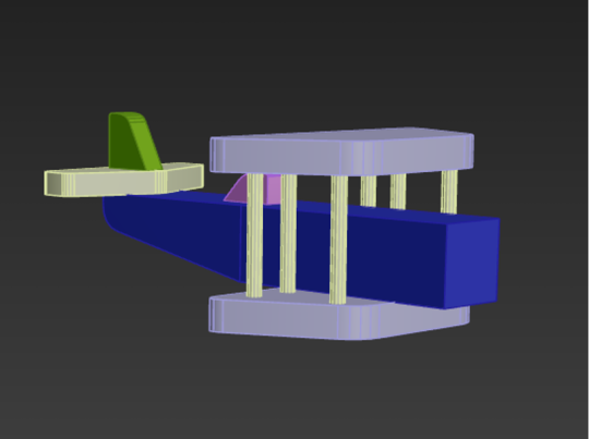
For the rods on either side of the planes wings, we duplicated a cylinder three times, spacing them out into a triangle shape. Then, with one cylinder still selected, we navigated to the right side of the screen and clicked the 'attach' button. We could then go around and click the other two pillars. This would combine the meshes together. You'll be able to tell if this endeavor was successful by clicking one of the pillars and having all three light up. A successful combining:

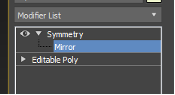
Then all that had to be done was mirror the object, which had to be done in a way that felt rather non-intuitive, but worked none the less.
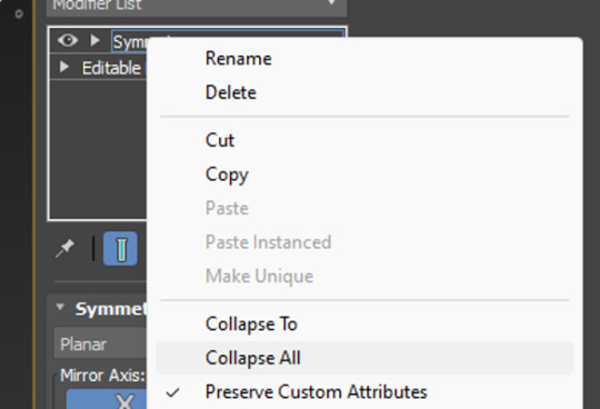
By accessing the 'modifier list' above the objects parameters, we could click the inbedded list and scroll through till we found symmetry. Once symmetry was added above our object mesh, we could click it's drop down and select mirror. Then using W,E,R, it's as easy as pulling on the mesh which will essentially duplicate it, but mirrored. To clean up, we can also collapse (basically a fancy way of saying merge) the symmetry drop down into our mesh to solidify it into one object. The many, many drop-downs needed to get there:
..............................................................................................................................
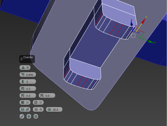
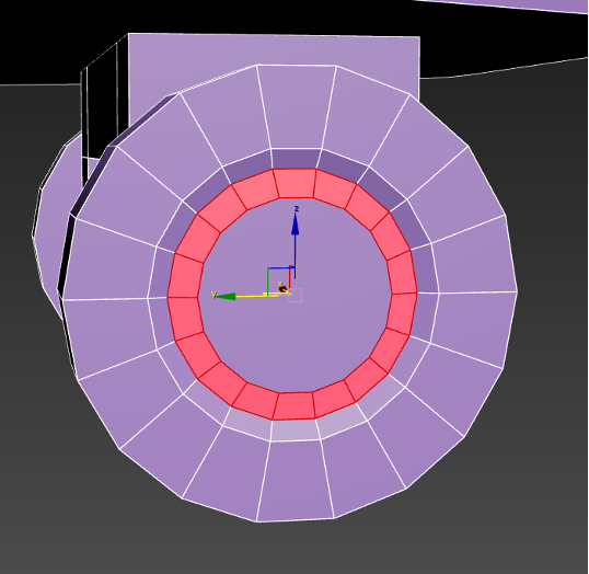
For the wheels and axle, we stuck a box on the underside of the bottom wing and added two cuts into it using the connect button (just like we did for the plane body). This time, instead of sliding the cut, however, we pinched it instead, allowing us to manipulate it and move it equally across the box. Cuts made in equal measure:

From there, we extruded the two faces either side of the cut, which adds protrusions to the original box shape, something I was familiar with thanks to last year. The height could be adjusted, and then I chamfered the edges for that nice rounded appearance.
Side note: Extruding is ten times easier in 3DS Max apparently. It tended to just... break a Maya model. Extruding protrusions:

Adding the wheels was simple. All we had to do was add a large cylinder, and inset three inner circles into it– another option that becomes available through the click of a button once the item becomes a polygon. All of this was create the illusion of hubcaps and depth on our wheels. Adding insets to the wheels to create a hubcap:
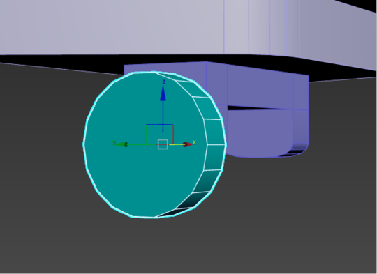
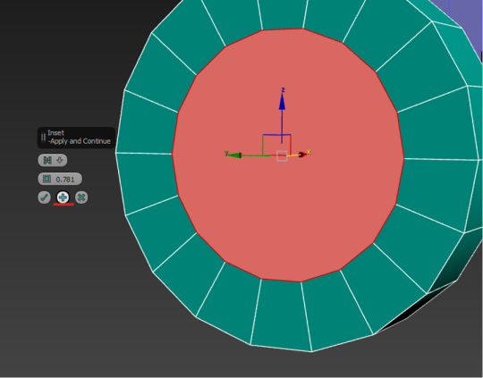
With three insets, I could double-click and use W,E,R to drag back the middle on to create a nice hubcappy illusion. I was pleasantly surprised at how nicely this worked.
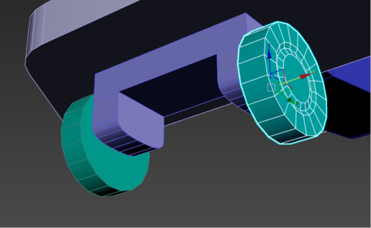
The single wheel could then be duplicated and flipped using W,E,R. I chose to snap mine to my plane for accuracy, though it could have just as equally been eyeballed. A hubcap!:
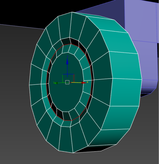
And, for a little extra flare, we smoothed out the faces we created, to get rid of the janky hard-edged looked. This was as simple as selecting the ring of faces we wanted, and going to the bottom right to apply an auto-smooth. The smoothing process:


..............................................................................................................................
The final little pieces were the front cone and propellers! The propellers were easy, just another box that got the chamfer treatment, but the cones were actually a little different.
Instead of using an actual cone primitive shape, we used a simple cylinder. By cutting a connecting loop into it and sliding it down to the base, we could then select the front and scale it using W,E,R. This was the top wouldn't be entirely pointed! Though be sure to use the triangle between the side and up arrows, this ensures you'll pull the mesh in and down in a pinching motion.
Cone-ception! It's actually a cylinder:

..............................................................................................................................
0 notes
Text
Single Row cylindrical Roller Bearing
Single Row cylindrical Roller Bearing Single-row cylindrical roller bearings are designed to support heavy radial loads and operate at high speeds. These bearings consist of a single row of cylindrical rollers in contact with the inner and outer raceway lines. This design allows for efficient load distribution and low friction, making it ideal for high-load and high-speed applications in industries such as automotive, aerospace and heavy machinery.
FTM single row cylindrical roller bearing customization: 1. Accuracy level: P2,P4 2. Material selection: bearing steel, Gcr15, 45 steel, stainless steel, etc 3. Size: diameter 10mm-25mm 4. Processing technology: chamfer, drilling, thread, groove, arc, heat treatment, electroplating, blackening, etc 5. Shape: Customize various shapes, car parts, casting, forging, etc
Design variables: Types N and NU: These types allow for axial displacement between the inner and outer rings, adapting to axial expansion caused by temperature changes. This is useful in applications with large thermal variations. Type NJ: Provides axial load capability in one direction, making it suitable for applications requiring limited axial support. NUP type: Provides axial load support in both directions and axial positioning in applications requiring light axial guidance.
Structure and components: Separable: Single-row cylindrical roller bearings are usually separable, which means that the inner and outer rings can be removed independently. This design simplifies installation, inspection and maintenance. Roller profile: Rollers are precision-machined with slightly raised tops to prevent edge stress, enhance load distribution, reduce wear and extend bearing life.
Application program: Motors: Ideal for high-speed motors because they are able to reduce friction while supporting significant radial loads. Gearboxes and transmissions: Often used for gearboxes with high radial loads because they provide stability under heavy and fluctuating loads. Pumps and compressor shafts: Common in applications that require reliability, low friction and high durability under constant radial loads.
Advantages: High radial load capacity: These bearings can support higher radial loads compared to ball bearings due to the linear contact of the cylindrical rollers. Low friction: They have low rolling friction, making them efficient for high-speed applications. Thermal expansion adjustment: Some designs (N and NU) allow for axial movement that helps accommodate thermal expansion without putting pressure on the bearing.
0 notes
Text
2.5mm Slight Court Standard Polished Chamfered Edges With Matt Centre Wedding Ring In 18 Carat Yellow Gold - Ring Size P
From the Goldsmiths Wedding Ring Collection, This 2. 5mm Slight Court Standard polished chamfered edges with matt centre Wedding Ring in 18 Carat Yell... http://dlvr.it/TFgLFr
0 notes
Text
Expert Guide to Installing Hydraulic Cylinder Seals for Optimal Performance
The usage of hydraulic cylinders is imperative across numerous industrial applications, while the efficiency much depends on what sort of seals are used within it. The hydraulic cylinder seals are crucial to keeping everything well sealed and contaminant free so the clogged up or leaking other wise they can end up costing you a lot of money not only in repairs but due to lost product to MJ downtimeowan over time. High demands placed on hydraulic systems over time can cause these seals to degrade and need replacement. This detailed guide offers how-to advice on replacing hydraulic cylinder seals to maximize life and maintain peak system operation.
The Importance of Hydraulic Cylinder Seals
Seals for hydraulic cylinders are critical for keeping pressure up, fluid moving well and debris out of the system. Piston seals, Rod Seals and V-Ring Seals several these types of seals doing different things at various points in the cylinder. Although different types of hydraulic cylinder seals serve as the game-changer in system performance. If seals wear out or fail, it can result in fluid leaks causing efficiency loss and even equipment shutdowns.
Installation of Hydraulic Cylinder Seal
Preparing to Replace Hydraulic Cylinder Seals Gather Your Tools Before you start fixing the hydraulic cylinder seals, it is important that yo only have get ready your workspace and but all tools on hand. In addition to making install a breeze, proper preparation can save you from the avoidable mistakes that cause most seals to fail.
a. Organize Your Workspace
First off, establish a neat and organized sanctuary designed for hydraulic cylinder maintenance. This will prevent contamination which can third new seals. Make sure that all tools and parts are clean, free of dirt It even helps you to easily track all the parts in installation.
b. Check the Work Materials and Supplies
Before we get to the point of installation, go over these components and make sure that everything with which your new seal will be interacting is in good condition. Ideally all the way in) inspecting the housing, lead-in chamfers and any other section where seal will be installed. Every surface must be clean, dry and free of any burs or cuts that could affect the seal. Also check your tools, if they are in good condition and capable of fulfilling this job.
c. Read Your Equipment Manual
Seal Installation Requirement for Each Hydraulic Cylinder Remember always to read the manual for that piece of equipment if there are special steps or precautions with a particular model. This is especially true on custom hydraulic cylinders or other applications where seal configurations can differ depending on the manufacturer and application.
Steps on How to Set Up Hydraulic Cylinder Seals
Installation of hydraulic cylinder seals is crucial to the longevity and efficiency of your equipment. Here is how to do it with confidence when changing the worn, or broken seals.
a. Remove the Old Seal
First, very cautiously take out the old or weaken seal from a hydraulic cylinder. You will likely need a seal pick or something similar. You also want to be very careful not to damage the surface of that cylinder in any way, because a scratch as small as what would fit into one cell from an 18-cell [inaudible] tubular battery can cause it later on down the road.
b. Install the New Seal
After removing the old seal, assemble a new hydraulic cylinder seal. Some are a little tricky to get in depending o the type of seal so it is good idea tto use just alitttr oil on the rubber. Place new seal around components and into groove. Part of the necessity is that a seal has to be placed in the groove properly or it could fail prematurely.
C. Covering Connections and Additional Links
Attach any fittings and secondary seals once the main seal is in position. These parts work in tandem to keep pressure and avoid leaking, so coming properly from the manufacturer is important at this point. Apply pressure against the new seal and wipe any oil or debris from where it was before, using a cloth
3) Final Inspection and Testing
Take this opportunity while the hydraulic cylinder is disassembled to give it a thorough cleaning. Don't forget to check the new seal for breaks or ensure it is fully nestled in ¶ Last but not least, make sure the cylinder is operational and functioning properly without leaks at all: The cylinder should be re-installed in its normal location only after these checks have been completed.
How to Choose the Correct Hydraulic Cylinder Seal Kit
Selecting the proper seal kit is paramount to hydraulic cylinder servicing success. Seal kits are available for each individual model of cylinder and come with all the necessary parts to completely rebuild it. However, if you are not sure which kit is right for you then it always best to get in contact with your hydraulic cylinders manufacturer. At XSLHydraulics.com , we produce top quality seal kits and make recommendations for your requirements.
This is Why Its Important to Install a Hydraulic Cylinder Seal Right
Because the seals you install have a direct effect on how your hydraulic cylinders will perform and for how long. By investing a little bit extra on quality seals and proper maintenance techniques, you can save time and money later by minimizing the risks of leaks, breakdowns or other equipment failures. Precision is vital when building components such as custom hydraulic cylinder manufacturing.
Conclusion
For replacement, hydraulic cylinder seals are the task that requires precision and done properly. If you just follow the instruction that this guide provides, then your hydraulic cylinder will work well for a longer time period and downtime can be reduced in many situations. Tie-rod, welded and telescopic hydraulic cylinders all require careful installation of seals for optimal functionality.
To learn more about hydraulic cylinder maintenance or to buy quality seal kits, go to XSLHydraulics.com. Our team of professionals are at the ready with our wealth of hydraulic cylinder knowledge, and equipment needed to keep you up and running around the globe.
0 notes
Text
Injection Mold Checklist
Excellence in manufacturing depends on injection frisbee quality. Our injection Mold Checklist simplifies this procedure, walking you through the necessary stages to uphold high standards. This checklist is an essential tool for any injection molding expert, as it includes all the necessary steps to optimize injection molding solutions, reduce errors, and increase productivity from original design to final inspection.
Mold appearance and dimension
Is the kind of water connector correct? Is there sufficient clearance in the hole for the water connector? The hole's outside border must be consistent and chamfered.
Indicate the water lines with "IN," "OUT," and neatly and legibly number them. For instance, INT1, OUT1.
Pneumatic or oil connection numbers must begin with the prefix "O" or "G," for example, G IN1, O IN1.
The gas, oil, and water plugs' screw threads all match the Tooling datasheet.
Are the KO pattern and size up to par?
The Locating ring's diameter and fastening type comply with the Tooling specification.
The tooling datasheet's sprue bushing sphere radius must be met.
The total size of the mold must satisfy the customer's press (tie bar space), and the clamping technique must satisfy the customer's demand.
When installing a mold that requires installation instruction, the cavity or core plate should be etched with an arrow that reads "UP."
Each part must have a unique number. Moreover, the standard mold datum needs to be etched.
It is not permitted to make any of the components within the home.
Using the right steel is important, and the molding injection company must submit the steel certification.
All connection screw threads, including K.O. and eyebolt holes, must be precise.
Wear plates should employ oil grooves whose designs adhere to client specifications.
The shut-off pieces must fulfill customer requirements and have a disparity in hardness.
Does Slide Gib require a dowel pin?
Are side locks properly purchased and installed?
Cycle Installing a counter as per the mold design sketch.
Make a vent opening for the guide bush.
Is a dustproof sheet required?
Are the slides assembled and properly fit the molding injection company?
The PL vent needs to be planned and cut. Is it directly cut to the part location and appropriate for parting?
Clearance space should be designed and created in the region beyond the portion wall. There is no need to invest in a grinding machine.
Sprue bushing should be OK and should not break.
Ejection, Return, Pull system and Removing
Smoothly ejecting, No unique sound, no get stick.
Lifter surfaces must be polished, lubricant slots must be made, and heat or nitride treatment must be applied (depending on the client's needs).
A & B plate guide pins, guide bushings, and ejector plate guide pins must satisfy client requirements.
Uneven ejector pins need to be placed in the molding injection company.
The ejecting plate ought to fully retract.
A flat-surfaced space block must be utilized for the ejecting stroke.
A return spring must be a normal part; it cannot be split or polished.
Does the material for the lifter, wedge block, and gib match the requirements of the customer? It must be heat-treated or nitride-treated.
Install a restricted switch on a hydraulic cylinder or slide.
The lifter stroke or slide must be sufficient to satisfy the requirements.
Both the ejector pin and the ejector plate must have the ejector number stamped on them.
Return pin top surfaces must be level and free of welding; bottom surfaces cannot have pillows or welding. The required hole clearance is 0.07 mm.
Unless otherwise noted, there should be 0.05mm of space between the B plate and the ejector guide pin (Conform to the molding injection company design specification).
With a sufficient stroke, the runner stripper plate moves smoothly.
The steel dimensions must be examined, and a steel check report must be submitted.
Cooling System
Water line seals must be leak-free, and utilize Teflon sealing tape.
Is the flow appropriate for cooling? To determine this, a flow metre must be used and the flow value recorded.
Cooling manifold installation must be done accurately and by client specifications.
The water baffle needs to fit the molding injection company specifications
Cold Runner System
Sprue bushing inside surface must be polished to design specifications.
It is necessary to polish the runner channel to the drawing standard.
For multi-molding injection company, the short-shot has to be tesmolding injection company.
Hot Runner System
Specifying the desired kind and size of sockets and installing safety settings is necessary.
Is there mold protection equipment placed on the outside of the connection box? The wiring must match the shop's given design.
To prevent breakage, wires must be bundled and covered with a plate.
When both connector sizes are the same, they must be carefully marked to prevent incorrect assembly.
Wires that are visible outside of the mold surface are prohibited.
The transition slot that allows the wire to pass through the plate and manifold must be rounded to prevent damage.
Does a mold-insulating plate exist? If not, has the consumer given their approval?
Mold Packing
The steel type, certification, and heat treatment must satisfy the client's needs.
Safety locks (at least two pieces) ought to fulfill the design specification, and a rest hole must be created.
The CD's files are full?
Are there any particular requirements for the outside surface of mold?
Are all the spare components filled up? And it must be supplied with a thorough list.
Mold must be wrapped in a plastic membrane.
After marking the positioning direction, spread mold # with lacquer.
Everything on the packing list must be packed.
Conclusion
In conclusion, obtaining consistent quality and operational efficiency requires the use of an injection mold checklist. You may drastically lower mistakes, raise the caliber of your output, and increase productivity by using this thorough guidance. By putting this checklist into practice, you can revolutionize your cheap injection molding process and make sure every project surpasses customer expectations and industry standards.
#plastic injection mold design#injection molding solutions#best injection molding company#injection frisbee#injection molding maker
0 notes
Text
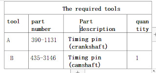
Caterpillar 311F LRR - JFT Crawler Excavator Engine Camshaft gear Removal and Installation
This article introducesCaterpillar 311F LRR - JFT Crawler Excavator Engine Camshaft gear Removal and Installation
-Removing and installation
Caterpillar ET 2024A & 2023C & 2019C Electronic Technician Diagnostic Software Download and Installation
Removing steps

begin:
A. Remove the rocker shaft and pushrod. For the correct steps, see Disassembly and Assembly, "Rocker Shaft and Purod-Remove".
pay attention to
Keep all the parts clean without impurities.
Impurities can cause rapid wear and shorten the service life of the components.
pay attention to
When inspecting, maintaining, testing, adjusting and repairing products, be careful to ensure that the liquid is held in the container. Before opening any chamber or disassembling any part with stored storage.
Dispose of all liquids in accordance with local regulations and instructions.
1. Remove the idler wheel. See Disassembly and Assembly, "Idler-Disassembly" for the correct steps.
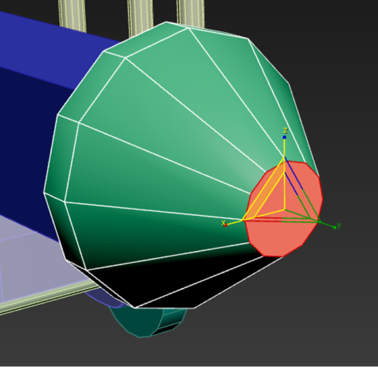
2. Ensure that the tool (A) is kept in place during the removal and installation steps of the camshaft gear.
3. Remove the tool (B).
graph 1
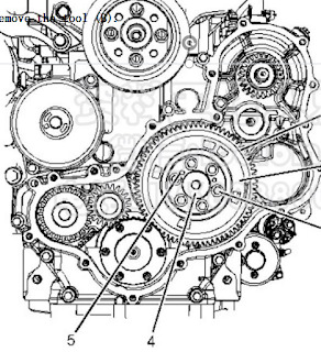
4. Remove the bolts (3) from the camshaft (4).
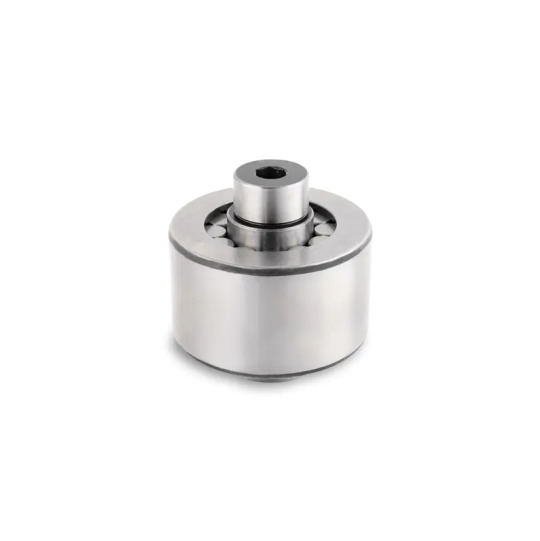
5. Remove the camshaft timing ring (2) from the positioning pin (5).
6. Remove camshaft gear (1) from camshaft (4) using tool (C). Caterpillar 18 Digits Factory Password Calculator One-Time Calculate Service
Installation steps
1. Ensure that all parts are clean and free from wear or damage. If necessary, replace all worn or damaged parts. 2. If tool (A) is not installed, install tool (A). For the correct steps, see Disassembly and Assembly, "Idler wheel-" dismantle ". 3. Lubricate the wheel teeth of the gears (1) with a clean engine oil.
4. Align the timing mark on the camshaft (4) position (V) with the timing mark on the front housing position (W).
5. Position the camshaft gear (1) on the camshaft (4). Ensure the positioning pin (6) is mounted into the hole (X) of the camshaft.
6. Ensure that the chamferals on the crankshaft gear position (Y) are between the timing marks on the camshaft gear position (Z).
7. Install the tool (B). See Disassembly and Assembly, "Idler-Disassembly" for the correct steps.
8. Install the camshaft timing ring (2) on the positioning pin (5).
9. Install the bolts (3) into the camshaft (4). Tighten the bolts to a torque of 25 N-m (221 lb in). End By : a. Install the inert wheel. For the correct steps, refer to Disassembly and Assembly, "Idler wheel-Install". b. Install the rocker arm shaft and push rod. See Disassembly and assembly, "Rocker shaft and pushrod installation" for the correct steps. CAT Caterpillar ET 3 Diagnostic Adapter 317-7485/478-0235 Diagnostic Tool-high quality
0 notes
Text

Rose Gold Rings | The Beautiful Company UK
Explore exquisite rose gold rings by The Beautiful Company UK. Find stunning designs crafted with precision and elegance. Discover your perfect rose gold ring today by visiting our website: https://www.thebeautifulcompany.co.uk/rose-gold-wedding-ring-chamfered-edge-6mm-cei6-r
#womens palladium wedding rings#8mm platinum wedding band#7mm platinum mens wedding band#4mm platinum mens wedding band#2mm yellow gold wedding band#4mm white gold wedding band#8mm platinum wedding ring#black and blue wedding band#channel rings#channel set diamond eternity ring#rose gold ring#rose gold rings#womens wedding rings#gold wedding rings women#womens gold wedding bands#womens gold wedding rings#rose gold wedding bands#rose gold bridal rings#mens wedding rings rose gold#rose gold mens wedding band#rose gold wedding band for him#rose gold marriage ring#mens rose gold wedding rings#rose gold wedding band men#rose gold wedding rings#rose gold diamond rings#rose gold rings for women#mens rose gold ring#rose gold wedding rings for women
0 notes
Text
WIP Atlesian Conlang Goals
DISCLAIMER: goals subject to change.
End goal.
For fun.
potential use in fiction
Vague Descriptions.
Technologically militant.
Worst of Russian.
Worst of German.
Strictly hierarchical.
Machine civilization.
Naturalism.
More natural.
Some unnatural features.
Complexity.
Fairly complex.
Agglutinative.
Longer words.
Derivation.
Mostly regular.
Some irregularities.
Features.
Phonology.
Word final stops/affricates.
consonant clusters.
/x/.
Diphthongs.
Palatalization.
Grammar.
Case.
Person-marking.
Direct requests.
Mantle dialect.
Engineering register with indirect requests.
Pronouns for machines.
Evidentiality.
Culture
Metaphor for society as a Machine.
Slurs/Pejoratives for Faunus.
Technology terms.
Military terms.
Orthography.
Alphabet.
Right-to-left top-to-bottom direction.
Squares.
Perpendicular lines.
90-degree angles.
Circles/Rings.
Chamfered corners.
#mvtjournalist speaks#conlang#constructed language#conlang idea#conlang goals#conlanging#language creation#language construction#rwby headcanon#rwby fanfiction#rwby atlas#atlesian
1 note
·
View note