#encoder in digital electronics
Explore tagged Tumblr posts
Visit Tumblr Blog
Explore Tumblr blogs with no restrictions, modern design and the best experience.
Last Seen Tumblr Blogs


Fun Fact
Tumblr Inc. has $15.1M in annual revenue.
Text
it's exciting that we're digitizing a lot of old manuscripts, not only because it makes them more available but also because it makes them easier to preserve. but i do kinda worry about what will happen to everything that's not digitized (or digitized but not transcribed) in the next 50 years as most new writing is written and transmitted electronically and old printing presses gradually close.
Historically the transition from one medium of literature to another has resulted in a significant loss: oral literature that wasn't written down wasn't learned by people who now primarily read books, works in languages or even dialects that weren't spoken anymore ceased to be copied, papyrus rolls that weren't copied into parchment codices were abandoned, etc. At least it's cheaper to save things now digitally compared to paying for someone to copy it out by hand but I even wonder how much that's being scanned is actually going to make it, it seems like we're not doing that much to make sure that these scans ever end up in a more durable format or make them available in multiple locations.
Also yeah if technological civilization collapses we'll lose everything that's not printed out on archival paper. but even if that doesn't ever happen, files will still be corrupted, encoding standards will become obsolete, and drives will fail. So it still seems like a lot of it will just disappear, mostly without anyone noticing until later.
38 notes
·
View notes
Text

An earth-abundant mineral for sustainable spintronics
In 2023, EPFL researchers succeeded in sending and storing data using charge-free magnetic waves called spin waves, rather than traditional electron flows. The team from the Lab of Nanoscale Magnetic Materials and Magnonics, led by Dirk Grundler, in the School of Engineering, used radiofrequency signals to excite spin waves enough to reverse the magnetization state of tiny nanomagnets. When switched from 0 to 1, for example, this allows the nanomagnets to store digital information, a process used in computer memory, and more broadly, in information and communication technologies. This work was a big step toward sustainable computing, because encoding data via spin waves (whose quasiparticles are called magnons) could eliminate the energy loss, or Joule heating, associated with electron-based devices. But at the time, the spin wave signals could not be used to reset the magnetic bits to overwrite existing data.
Read more.
13 notes
·
View notes
Text
Residual Data Interruption (RDI) - Part donation and reuse is a common practice among Transformers, from both living and dead donors. When done properly, electronic parts are sanitized both physically and digitally, exposed to electromagnetic frequencies to wipe the parts clean of the donor's information before installing it into the recipient, where their frame will re-encode it to their specifications.
However, when this step is done improperly, or not taken at all, the data left on the transplanted part will express itself as it resumes its normal function. The recipient's datastream will occasionally process old code before returning to normal. Typically, this results in harmless expressions of the donor's code, like changes in appetite, physicality, and slight fluctuations of vitals.
Part rejection, which is possible even for properly wiped transplants, can result in illness or injury.
Symptoms vary depending on the nature of the transplant. The closer the part is to their central neural network, the more dangerous residual data becomes. Recorded extreme cases involve unusual nocturnal subroutines (dreams). Worst case is Idle Servos, which is a scenario that has luckily never been recorded happening.
It must be noted the Transformation cog is immune to RDI. It allows a Transformer to shift their frame the way it was designed, information which is not stored in the T-cog, and thus is interchangeable. Improperly transplanted or ill-fitting/incompatible cogs will merely disrupt the process of transforming.
Post-mortem donors can indicate their wishes prior to deactivation; in cases where they do not, permission must be given from a superior to harvest parts. The latter is typically done in times of hardship and scarcity.
12 notes
·
View notes
Text
Not Bad.
In my wandering around the internoise I find a lot of errors. Errors of fact which in turn lead to confusion and poor assumptions.
I often comment on two dichotomies in the audio world. One is of course tube versus solid state electronics. The other is digital versus analog recording and play back. In both areas either side can provide excellent performance.
I have and appreciate both digital and analog recordings.
I have and appreciate both tube and solid state electronics.
Each are different. I have preferences. Neither is inherently bad.
Other people get wound up and committed to this side or that. Recently I read a person saying that vinyl albums have a limited frequency response so they are obviously inferior just for that. London ffrr recordings claimed up to 16khz which is pretty good, and CDs are good to 22khz ( 1/2 of 44khz or the Nyquist frequency) end of debate, so there.
The CD could easily produce up to the theoretical limit of human hearing. I think all digital methods have a similar limit as even with very high carrier frequencies they are filtered to pass nothing above 20khz. That is to facilitate low slopes in the output filters of Class D amplifiers for example. Academic for me as my hearing quits at 12 khz.
But what is the actual limit of LP frequency response? How about 45 khz. Back in the 1970s several companies tried to make quadraphonic sound. They encoded rear channel signals using a high frequency modulation on top of the normal music signal. It did not work all that well, and there were several competing standards and nobody won. But it did fundamentally work.
They produced stereo phono cartridges and LPs with 45 khz information on them using basically the methods used before and since. They made LPs with ultrasonic signals on them. They developed styli that were finer to track this information such as the Shibata which are still made.
My Signet TK7E cartridge was rated to respond to 45 khz. The better Grado cartridges also go that high. The top of the line Grado is rated to 70 khz. This is vinyl technology we have here with at least double the frequency response of digital methods. So no vinyl is not inferior in terms of frequency response potential.
We are of course talking about best case potential, but they did put this stuff out in the market. It actually worked.
Oh CDs have superior dynamic range, but like 20khz high frequency limit can you even use it? If the information is not on the recording does it even matter? LPs have enough for 95% of the time. I have a single CD with an extreme dynamic range where the quiet is very quiet, but turning it up to hear that part of the music makes the loud bit deafening. (KODO)
More recent digital methods have even better dynamic range. The actual use for that is in the recordings, not the playback.
Analog versus digital quality depends on production more than potential. In terms of best neither is. Oh MP3s suck generally as the priority there was compactness not quality. CDs, DSD, High res streams are fine.
And as far as tube versus solid lumps of semi-conductors well it is kinda the same. Computers and Class D amplifiers use MOSFET materials and those run at gigahertz. There are consumer vacuum tube amps that respond up to 100khz fine, and go down to 10 Hz as well. Either technology has far more potential performance than anyone can use.
Both types can have very low distortion. At normal listening levels the percentage is minuscule. Different voice and such is real but due to other things which to me are almost like black magic. My freshly retubed ARC amp sounds far more clear than before. It is still different than my old SS amp.
This stuff is not bad.
2 notes
·
View notes
Text
New transistor’s superlative properties could have broad electronics applications
New Post has been published on https://thedigitalinsider.com/new-transistors-superlative-properties-could-have-broad-electronics-applications/
New transistor’s superlative properties could have broad electronics applications
In 2021, a team led by MIT physicists reported creating a new ultrathin ferroelectric material, or one where positive and negative charges separate into different layers. At the time they noted the material’s potential for applications in computer memory and much more. Now the same core team and colleagues — including two from the lab next door — have built a transistor with that material and shown that its properties are so useful that it could change the world of electronics.
Although the team’s results are based on a single transistor in the lab, “in several aspects its properties already meet or exceed industry standards” for the ferroelectric transistors produced today, says Pablo Jarillo-Herrero, the Cecil and Ida Green Professor of Physics, who led the work with professor of physics Raymond Ashoori. Both are also affiliated with the Materials Research Laboratory.
“In my lab we primarily do fundamental physics. This is one of the first, and perhaps most dramatic, examples of how very basic science has led to something that could have a major impact on applications,” Jarillo-Herrero says.
Says Ashoori, “When I think of my whole career in physics, this is the work that I think 10 to 20 years from now could change the world.”
Among the new transistor’s superlative properties:
It can switch between positive and negative charges — essentially the ones and zeros of digital information — at very high speeds, on nanosecond time scales. (A nanosecond is a billionth of a second.)
It is extremely tough. After 100 billion switches it still worked with no signs of degradation.
The material behind the magic is only billionths of a meter thick, one of the thinnest of its kind in the world. That, in turn, could allow for much denser computer memory storage. It could also lead to much more energy-efficient transistors because the voltage required for switching scales with material thickness. (Ultrathin equals ultralow voltages.)
The work is reported in a recent issue of Science. The co-first authors of the paper are Kenji Yasuda, now an assistant professor at Cornell University, and Evan Zalys-Geller, now at Atom Computing. Additional authors are Xirui Wang, an MIT graduate student in physics; Daniel Bennett and Efthimios Kaxiras of Harvard University; Suraj S. Cheema, an assistant professor in MIT’s Department of Electrical Engineering and Computer Science and an affiliate of the Research Laboratory of Electronics; and Kenji Watanabe and Takashi Taniguchi of the National Institute for Materials Science in Japan.
What they did
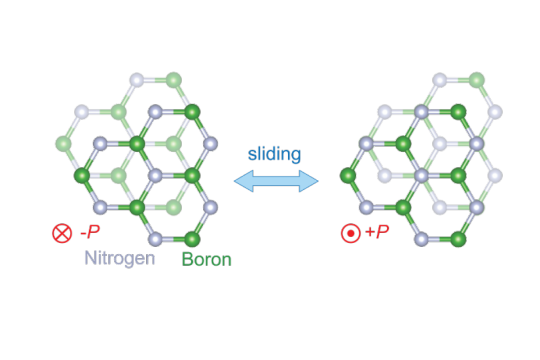
In a ferroelectric material, positive and negative charges spontaneously head to different sides, or poles. Upon the application of an external electric field, those charges switch sides, reversing the polarization. Switching the polarization can be used to encode digital information, and that information will be nonvolatile, or stable over time. It won’t change unless an electric field is applied. For a ferroelectric to have broad application to electronics, all of this needs to happen at room temperature.
The new ferroelectric material reported in Science in 2021 is based on atomically thin sheets of boron nitride that are stacked parallel to each other, a configuration that doesn’t exist in nature. In bulk boron nitride, the individual layers of boron nitride are instead rotated by 180 degrees.
It turns out that when an electric field is applied to this parallel stacked configuration, one layer of the new boron nitride material slides over the other, slightly changing the positions of the boron and nitrogen atoms. For example, imagine that each of your hands is composed of only one layer of cells. The new phenomenon is akin to pressing your hands together then slightly shifting one above the other.
“So the miracle is that by sliding the two layers a few angstroms, you end up with radically different electronics,” says Ashoori. The diameter of an atom is about 1 angstrom.
Another miracle: “nothing wears out in the sliding,” Ashoori continues. That’s why the new transistor could be switched 100 billion times without degrading. Compare that to the memory in a flash drive made with conventional materials. “Each time you write and erase a flash memory, you get some degradation,” says Ashoori. “Over time, it wears out, which means that you have to use some very sophisticated methods for distributing where you’re reading and writing on the chip.” The new material could make those steps obsolete.
A collaborative effort
Yasuda, the co-first author of the current Science paper, applauds the collaborations involved in the work. Among them, “we [Jarillo-Herrero’s team] made the material and, together with Ray [Ashoori] and [co-first author] Evan [Zalys-Geller], we measured its characteristics in detail. That was very exciting.” Says Ashoori, “many of the techniques in my lab just naturally applied to work that was going on in the lab next door. It’s been a lot of fun.”
Ashoori notes that “there’s a lot of interesting physics behind this” that could be explored. For example, “if you think about the two layers sliding past each other, where does that sliding start?” In addition, says Yasuda, could the ferroelectricity be triggered with something other than electricity, like an optical pulse? And is there a fundamental limit to the amount of switches the material can make?
Challenges remain. For example, the current way of producing the new ferroelectrics is difficult and not conducive to mass manufacturing. “We made a single transistor as a demonstration. If people could grow these materials on the wafer scale, we could create many, many more,” says Yasuda. He notes that different groups are already working to that end.
Concludes Ashoori, “There are a few problems. But if you solve them, this material fits in so many ways into potential future electronics. It’s very exciting.”
This work was supported by the U.S. Army Research Office, the MIT/Microsystems Technology Laboratories Samsung Semiconductor Research Fund, the U.S. National Science Foundation, the Gordon and Betty Moore Foundation, the Ramon Areces Foundation, the Basic Energy Sciences program of the U.S. Department of Energy, the Japan Society for the Promotion of Science, and the Ministry of Education, Culture, Sports, Science and Technology (MEXT) of Japan.
#2-D#affiliate#applications#atom#atoms#author#billion#boron nitride#career#Cells#change#chip#collaborative#computer#computer memory#Computer Science#Computer science and technology#computing#education#electric field#Electrical Engineering&Computer Science (eecs)#electricity#Electronics#energy#engineering#flash#Foundation#Fundamental#Future#green
2 notes
·
View notes
Text

Comprehensive Guide to Video Encoding and Content Delivery
In today's digital age, video content has become an integral part of our daily lives, from streaming movies and TV shows to video conferencing and online tutorials. Behind the seamless delivery of these videos lies the complex world of video encoding. This comprehensive guide aims to demystify video encoding, covering fundamental concepts, adaptive bitrate streaming (ABS), content-aware encoding (CAE), and the role of XML-based Electronic Program Guides (EPGs) in the television industry.
1. Introduction to Video Encoding
Fundamental Concepts
Video encoding involves the conversion of raw video data into a digital format that can be efficiently transmitted, stored, and played back. Key concepts include:
Codecs: These are algorithms used to compress and decompress video data. Popular codecs include H.264, H.265 (HEVC), and VP9.
Bitrates: Bitrates refer to the amount of data processed per unit of time and are crucial for determining video quality and file size.
Container Formats: These formats encapsulate video, audio, and metadata into a single file, with examples including MP4, AVI, and MKV.
Importance of Video Encoding
Video encoding plays a vital role in content delivery and distribution, impacting factors such as streaming quality, bandwidth consumption, and storage requirements. Efficient video encoding ensures optimal viewing experiences across various devices and network conditions.
2. Adaptive Bitrate Streaming (ABS)
Principles of ABS
Adaptive Bitrate Streaming (ABS) dynamically adjusts video quality based on the viewer's network conditions, ensuring smooth playback and minimizing buffering. It achieves this by delivering video in multiple bitrates and resolutions, allowing seamless transitions between them.
Benefits of ABS
ABS offers several benefits, including improved user experience, reduced buffering, and efficient bandwidth utilization. Popular ABS technologies such as HTTP Live Streaming (HLS) and Dynamic Adaptive Streaming over HTTP (DASH) are widely used for online video streaming and live broadcasts.
3. Content-Aware Encoding (CAE)
Concept of CAE
Content-Aware Encoding (CAE) optimizes video encoding based on the characteristics of the content itself. This approach focuses on maximizing visual quality while minimizing file sizes, leading to better quality-to-bitrate ratios and improved streaming efficiency.
Advantages of CAE
CAE techniques, such as scene-aware encoding and object-based encoding, offer advantages such as reduced file sizes, improved visual quality, and enhanced streaming performance. Content providers can leverage CAE to deliver high-quality videos while conserving bandwidth.
4. XML EPG for TV
Role of XML EPGs
XML-based Electronic Program Guides (EPGs) serve as comprehensive databases of TV programming information, including channel listings, show descriptions, and scheduling details. They enable viewers to access detailed program information and make informed viewing choices.
Benefits of XML EPGs
XML EPGs benefit both content providers and viewers by enhancing content discovery, supporting personalized recommendations, and enabling interactive TV experiences. They play a crucial role in modern television services, enriching the viewer's entertainment experience.
Video encoding and content delivery technologies continues to rise, shaping the way we consume and interact with video content.
Understanding the principles of video encoding, adaptive bitrate streaming, content-aware encoding, and xmltv schedule epg guide is essential for content creators, broadcasters, and streaming platforms.
By harnessing these technologies, the industry can deliver immersive, high-quality video experiences while adapting to diverse viewer preferences and network conditions.
Whether you're a video enthusiast, content creator, or industry professional, embracing these concepts can elevate the quality and accessibility of video content in today's digital landscape.
Stay tuned for more insights into the ever-improving world of video technology and content delivery. Get the needed info, to discover where to find the best xmltv schedule epg, and never miss a TV show again! Access reliable sources for up-to-date TV listings and enhance your viewing experience today.
youtube
5 notes
·
View notes
Text

2024-09-11: Episode 11 (We Interrupt This Broadcast...)
Original airdate September 9, 1992
Episode Synopsis
Local Fresno TV station KLIK is doing an interview with Dr. Beeker when a an unexpected lightning storm appears in the area. Right after Dr. Beeker's interview starts, the station is struck by lightning and the mass of cables and station equipment in the newsroom becomes a sentient hive-like amalgamation of video production equipment known as Spectrum. The gang must make their way to KLIK and fight their way through the hordes of electronics to rescue Dr. Beeker and put a stop to Spectrum's rampage.
Episode Sponsor: MagnaSphere
A science kit for kids age 5-12 that was somewhat unusual among the episode sponsors in that it was exclusively educational in nature and didn't rely on licensed characters or gimmicks to boost sales. Magnasphere's name came from the several round dipole magnets that were used to learn about magnetism in the "seven mind-blowing experiments you can do at home!"
Notable Element of the Episode: The Rig (Item)
In the closets and also in the news van are collections of video equipment known only as The Rig that is used for field reporting or backups in the event of a camera failure. Because they aren't plugged into the building's electrical system or it's video feed, these battery powered camera/microphone sets are not affected by Spectrum's presence and can be used to sneak through areas controlled by Spectrum, to act as reconnaissance, or to give orders to Spectrum controlled hardware (if the gang possesses the digital data stream to encode messages to make it seem like it's from Spectrum itself). There is one Rig in each of the two news vans, and another Rig in the hallway closet outside the studio. The Rig's reliance on batteries means that it can only operate for 10 minutes before running out of power, and although The Rig does not have to run continuously to save power, each time it is powered up takes a minimum of 2 minutes from the remaining run time.
2 notes
·
View notes
Text
Year of the Depend Adult Undergarment:
InterLace TelEntertainment, 932/1864 R.I.S.C. power-TPs w/ or w/o console, Pink2, post-Primestar D.S.S. dissemination,
menus and icons, pixel-free InterNet Fax, tri- and quad-modems w/ adjustable baud, post-Web Dissemination-Grids, screens so
hígh-def you might as well be there, cost-effective videophonic conferencing, internal Froxx CD-ROM, electronic couture, all-in-
one consoles, Yushityu ceramic nanoprocessors, laser chromatography, Virtual-capable media-cards, fiber-optic pulse, digital
encoding, killer apps; carpal neuralgia, phosphenic migraine, gluteal hyperadiposity, lumbar stressae

lions are very mean and like jellyfish
73K notes
·
View notes
Text
Encrypted Flash Drives Market : Size, Trends, and Growth Analysis 2032
Encrypted Flash Drives Market: Enhancing Data Security in a Digital Age
The Encrypted Flash Drives Market was valued at US$ 105.90 Million in 2024 and is expected to grow at a CAGR of 7.99% from 2025 to 2032. As data breaches and cyber threats continue to escalate globally, the demand for secure portable storage solutions such as encrypted flash drives is surging.
Understanding Encrypted Flash Drives
Encrypted flash drives are USB-based storage devices embedded with encryption technology to secure data at rest. Unlike conventional flash drives, these devices use sophisticated encryption algorithms — often hardware-based — to encode data, ensuring that unauthorized users cannot access stored information without the correct decryption key or password.
The hardware encryption offers a superior layer of protection compared to software-only encryption solutions, safeguarding against malware attacks, hacking attempts, or physical theft. These devices are widely used across industries such as finance, healthcare, government, and defense, where safeguarding sensitive data is paramount.
Market Drivers
1. Increasing Data Privacy and Security Regulations Stringent data protection laws worldwide, including GDPR in Europe, HIPAA in the U.S., and similar regulations in other regions, are compelling organizations to adopt robust data security measures. Encrypted flash drives help companies comply with these regulations by protecting data during transit and storage.
2. Rising Cybersecurity Threats With escalating cyberattacks, ransomware incidents, and insider threats, organizations seek reliable solutions to prevent unauthorized access. Encrypted flash drives provide a secure method for data transport without compromising confidentiality.
3. Growing Adoption Across Verticals Industries like healthcare require encrypted drives to secure patient data; financial institutions use them to protect transaction records; government agencies rely on them for classified information. The broad application across verticals fuels market growth.
4. Increasing Remote Work and Data Mobility The rise of remote work has amplified the need for secure portable storage. Employees and contractors often transfer sensitive data across networks and devices, and encrypted flash drives provide a secure physical medium for such transfers.
Key Features and Benefits
Hardware-Based Encryption: Many encrypted flash drives use AES 256-bit encryption, ensuring robust data protection independent of host device security.
Password Protection and Multi-Factor Authentication: Some models support biometric verification or require multi-layered authentication to unlock data access.
Tamper-Resistant Design: Devices often come with rugged casings, tamper-evident features, and self-destruct mechanisms to safeguard against physical attacks.
Cross-Platform Compatibility: These drives typically support multiple operating systems including Windows, macOS, and Linux, ensuring wide usability.
Challenges in the Market
Despite the growing demand, the encrypted flash drives market faces some challenges:
Higher Cost Compared to Conventional Drives: The added encryption and security features increase the price point, which can be a barrier for price-sensitive customers.
User Awareness and Adoption: Some organizations still rely on traditional storage methods or software encryption due to lack of awareness or perceived complexity of hardware-encrypted drives.
Potential Performance Overheads: Encryption and decryption processes may slightly affect data transfer speeds compared to non-encrypted flash drives.
Market Segmentation
By Product Type:
Hardware Encrypted Flash Drives
Software Encrypted Flash Drives
By Application:
Government & Defense
BFSI (Banking, Financial Services, and Insurance)
Healthcare
IT & Telecom
Consumer Electronics
Others
By Region:
North America
Europe
Asia-Pacific
Rest of the World
North America dominates the market due to stringent cybersecurity regulations and high adoption of advanced security technologies. Asia-Pacific is expected to register rapid growth owing to increasing digitalization and rising awareness about data protection.
Competitive Landscape
The encrypted flash drives market is highly competitive with several key players investing in R&D to enhance product features and expand their product portfolios:
ADATA Technology: Known for reliable and affordable encrypted drives with robust hardware encryption and rugged designs.
Samsung: Offers a range of secure flash storage solutions emphasizing speed and durability alongside encryption.
Kingston Technology: A leading manufacturer with a comprehensive lineup of encrypted flash drives featuring hardware encryption and multi-factor authentication.
Transcend Information: Focuses on enterprise-grade encrypted drives with advanced security management features.
Corsair: Provides high-performance encrypted drives targeting professional and consumer segments.
Seagate Technology: Combines storage capacity and data protection through advanced encryption technologies.
Micron Technology: Known for innovative memory and storage solutions including secure flash drives.
Apricorn: Specializes in hardware-encrypted flash drives with certified security standards suitable for government and corporate use.
Industry Trends and Innovations
Integration of Biometric Authentication: Emerging encrypted flash drives incorporate fingerprint sensors to enhance security and usability.
Cloud-Integrated Secure Storage: Some solutions now offer hybrid models combining encrypted flash drives with cloud backup and remote wipe features.
Compact and Rugged Designs: Manufacturers are focusing on making drives smaller, durable, and water-resistant for field use in harsh environments.
Enterprise Security Management: Advanced management software allows IT administrators to control, monitor, and audit encrypted flash drives deployed within organizations.
Future Outlook
The encrypted flash drives market is expected to witness consistent growth as digital transformation intensifies and data security becomes a top priority for enterprises globally. With cyber threats growing in sophistication, demand for hardware-based secure storage solutions will increase.
Companies focusing on innovation in encryption technologies, ease of use, and compliance with international security standards will likely gain competitive advantages. The proliferation of IoT, mobile computing, and edge devices will also boost demand for portable yet secure data storage options like encrypted flash drives.
Browse more Report:
Industrial Discrete Semiconductor Market
EUV Pellicle Market
Encrypted Flash Drives Market
Electronic Materials and Chemicals Market
E-Beam Wafer Inspection System Market
0 notes
Text
Understanding the Role of Hollow Shaft Rotary Encoders in Modern Robotics
Introduction to Rotary Encoders in Robotics
Rotary encoders are fundamental components in robotic systems, serving as critical feedback devices that measure the rotation, position, and direction of motor shafts. These sensors translate mechanical motion into electrical signals, which control systems then interpret to ensure precise movement. Among the various types of rotary encoders, hollow shaft rotary encoders have emerged as a key player due to their compact design, ease of integration, and high reliability. As robotics continues to permeate sectors like manufacturing, healthcare, logistics, and consumer electronics, understanding the specific contributions of hollow shaft rotary encoders becomes vital. Their importance lies not only in their functional capabilities but also in how they influence design flexibility and performance optimization in robotic applications. By integrating seamlessly into existing architectures, these encoders reduce mechanical complexity while improving feedback accuracy. This comprehensive examination will explore how these components are revolutionizing modern robotics, from their design advantages to their roles in various robotic subsystems.
Evolution of Rotary Encoders and Robotic Needs
The development of rotary encoders parallels the evolution of robotics itself. Early robotic systems relied on open-loop controls, often leading to inaccuracies and inefficiencies. As the demand for precision and repeatability grew, rotary encoders became indispensable. Initially, these sensors were bulky and susceptible to environmental interference. Over time, however, innovations in materials, signal processing, and miniaturization led to more robust and compact designs. Hollow shaft rotary encoders, in particular, emerged as a response to the need for space-saving yet highly accurate feedback devices. Robotics has evolved from simple pick-and-place machines to complex, autonomous entities requiring precise coordination across multiple axes. This shift necessitated encoders capable of delivering consistent, high-resolution feedback without contributing to design bulk. In mobile robots, surgical devices, and industrial arms, space is a premium commodity. Hollow shaft encoders allow engineers to route cables or mechanical shafts through the encoder's center, optimizing spatial configuration and reducing wear on moving parts. This evolution marks a significant turning point in the interplay between sensor technology and robotic capability.
Anatomy of a Hollow Shaft Rotary Encoder
At its core, a hollow shaft rotary encoder consists of a rotor, stator, and signal processing circuitry housed in a compact unit. What distinguishes it from other encoder types is the central hollow section through which a shaft or cabling can pass. This seemingly simple design offers substantial advantages. The rotor attaches directly to the rotating shaft, while the stator remains fixed to the structure. As the shaft turns, the encoder senses the angular displacement and transmits corresponding electrical signals. These signals may be digital or analog, depending on the encoder type and application. Typically, hollow shaft encoders utilize optical, magnetic, or capacitive technologies to detect movement. Optical encoders, for instance, use a light source and a photo-detector array to interpret interruptions in a coded disc. This method provides high-resolution data, essential for robotic operations requiring micrometer-level precision. Additionally, many hollow shaft encoders incorporate features like integrated bearings, multi-turn tracking, and error correction protocols, ensuring they maintain accuracy even under high-speed or high-vibration conditions.
Integration in Robotic Joint Systems
One of the primary applications of hollow shaft rotary encoders in robotics is within joint systems. Whether in humanoid robots or articulated industrial arms, joint movement must be monitored and controlled with utmost precision. Hollow shaft encoders facilitate this by being mounted directly onto the joint actuators, enabling real-time position feedback. Their hollow design allows power and data cables to pass through the joint axis, reducing external cabling and potential points of failure. This configuration not only enhances the mechanical efficiency of the joint but also simplifies maintenance and design. In collaborative robots, or cobots, where safety and fluid motion are paramount, these encoders help ensure smooth articulation and responsive behavior. They support closed-loop control systems that adjust motor output dynamically based on encoder feedback. This loop is crucial for tasks like pick-and-place operations, precision welding, or surgical manipulations, where even millimeter-level deviations can compromise functionality or safety. By offering a balance of compactness, accuracy, and reliability, hollow shaft rotary encoders are central to robotic articulation systems.
Enhancing Mobility in Autonomous Robots
Autonomous mobile robots (AMRs) require robust sensory systems to navigate complex environments accurately. Hollow shaft rotary encoders play an essential role in this context by providing reliable feedback on wheel or track rotation. Unlike incremental encoders that only track changes in position, absolute feedback systems offer the advantage of positional memory. This becomes crucial in navigation, where knowing the robot's exact orientation at any given time determines path planning and obstacle avoidance efficacy. In differential drive systems, for instance, encoders mounted on each wheel shaft measure relative speeds and directions, allowing for accurate steering and speed control. The compact nature of hollow shaft encoders is especially beneficial in mobile platforms, where every millimeter of space impacts battery size, payload capacity, or sensor load. Their integration also enhances durability since fewer external mechanical parts mean less exposure to dust, moisture, or mechanical wear. This synergy of design efficiency and functional robustness makes hollow shaft encoders indispensable in robotic mobility subsystems.
Role in Precision Tasks and Fine Manipulation
Modern robotics increasingly involves tasks requiring fine motor control, such as electronic assembly, 3D printing, and medical interventions. In these scenarios, the encoder’s resolution and responsiveness directly impact task accuracy. Hollow shaft rotary encoders contribute significantly by enabling micro-adjustments based on real-time positional data. In robotic arms used for electronic manufacturing, for instance, components must be placed with sub-millimeter accuracy. The encoder's feedback ensures that the tool tip follows the programmed path without deviation. Similarly, in 3D printing, layer consistency and nozzle positioning depend heavily on precise rotary feedback. Medical robotics, particularly in minimally invasive surgery, represents another frontier where precision is non-negotiable. Here, hollow shaft encoders are used in tool actuation systems, allowing surgeons to perform complex procedures remotely with high confidence in the robot's positional accuracy. The encoders’ inherent design also aids in sterilization and integration within tight surgical tool assemblies. Thus, their role extends from mechanical feedback to enabling new capabilities in high-precision robotic tasks.
Environmental Robustness and Industrial Viability
Robotic systems often operate in harsh environments—factories, outdoor settings, or hazardous locations. Devices integrated into such systems must exhibit resilience to temperature fluctuations, vibrations, dust, and moisture. Hollow shaft rotary encoders are increasingly engineered with these challenges in mind. Manufacturers offer variants with IP-rated enclosures, corrosion-resistant materials, and sealed optical systems. This robustness allows them to function reliably in automotive assembly lines, mining robots, or agricultural drones. In temperature-controlled warehouse automation, for example, encoders must perform consistently despite frequent exposure to cold or variable humidity levels. The absence of exposed cables and the encoder’s enclosed design minimize contamination risks and mechanical wear. These features contribute to lower maintenance demands and longer operational lifespans, which are critical in high-throughput industrial settings. Moreover, their compatibility with various communication protocols—such as EtherCAT, CANopen, and SSI—ensures that they can be integrated into diverse control architectures without extensive modification. This adaptability further cements their place in modern industrial robotics.
Supporting Safety and Redundancy Mechanisms
Safety is a fundamental concern in robotics, particularly in collaborative or human-facing environments. Encoders play a vital role in ensuring operational safety by providing accurate position feedback for motion verification and error detection. Hollow shaft rotary encoders are especially suited for redundant systems, where multiple sensors verify each other's outputs. This redundancy ensures that if one sensor fails, the system can continue operating safely or shut down in a controlled manner. In safety-rated robotic arms, encoders are often employed in tandem with other sensors to monitor limits and ensure compliance with predefined safety envelopes. Their high resolution and low latency make them ideal for such critical feedback loops. Additionally, their compact form factor allows for integration into secondary safety circuits without adding bulk. The feedback from these encoders also enables soft-limit programming, which prevents actuators from moving beyond safe zones. In service robots or exoskeletons, where human safety is paramount, this encoder-driven feedback becomes essential for real-time decision-making and reactive control.
Future Outlook: Smart Integration and Predictive Maintenance
As robotics evolves towards greater autonomy and intelligence, the role of feedback devices like hollow shaft rotary encoders is also transforming. Modern encoders are increasingly being equipped with smart features such as self-diagnostics, condition monitoring, and real-time data streaming. These capabilities feed into predictive maintenance systems, helping operators detect wear or misalignment before it causes failure. For example, by monitoring signal consistency or rotational anomalies, the encoder can alert the system to potential mechanical issues. This proactive approach reduces downtime and extends the life of robotic assets. Furthermore, as artificial intelligence becomes integral to robotics, encoder data can be used to train machine learning models for movement optimization and adaptive control. Smart encoders also support advanced communication standards that facilitate seamless integration into IoT-enabled infrastructures. This trend indicates a shift from passive sensing to active data contribution, where encoders not only report motion but also enhance system intelligence. Such evolution positions hollow shaft rotary encoders as foundational components in next-generation robotic ecosystems.
Precision Engineering Meets Practical Application
The intersection of precision engineering and practical robotic application is where hollow shaft rotary encoders demonstrate their full potential. As manufacturing tolerances tighten and robotic roles diversify, the demand for encoders that can deliver high-resolution feedback in compact, rugged packages continues to grow. These devices are not only vital for motion tracking but also contribute to reducing system complexity, enhancing safety, and enabling adaptive control. Their utility spans industries and use-cases, from autonomous warehouse robots to robotic-assisted surgery. As designers push the boundaries of what robots can achieve, they increasingly turn to encoders that offer a balance of size, accuracy, and integration flexibility. Among these, the hollow shaft rotary encoder stands out for its ability to combine mechanical elegance with technical performance. Its role in facilitating the compact, precise, and reliable movement is central to the continued advancement of robotics.
Enhancing Control Through Advanced Feedback Systems
In many robotic systems, especially those with complex kinematics, advanced feedback is necessary to synchronize multiple actuators. Here, the absolute rotary encoder proves instrumental. By providing unique position values that do not require recalibration after power loss, these encoders enhance system reliability and responsiveness. This becomes particularly valuable in automated systems that must resume operation immediately after interruptions. Their use simplifies control algorithms and reduces computational overhead, which in turn allows for more fluid and responsive robotic behavior. From industrial automation lines to mobile robotic platforms, absolute encoders bring consistency and predictability, even under dynamic load changes or complex trajectories. When integrated with real-time control loops, they enable smoother transitions, better torque management, and reduced mechanical stress. These benefits contribute to more agile and longer-lasting robotic systems.
Meeting Modern Demands with Cutting-Edge Solutions
The robotic landscape is shifting rapidly, driven by needs for flexibility, scalability, and intelligence. In this context, the absolute position encoder emerges as a critical component, especially in scenarios where exact positioning is non-negotiable. Whether it’s aligning robotic cameras, controlling prosthetic limbs, or managing the angular position of robotic grippers, these encoders deliver the granularity required for high-precision tasks. They also facilitate seamless feedback for AI-driven decisions, particularly in adaptive robotics that interact with unpredictable environments. The encoder's ability to provide exact position data without drift ensures consistent performance across repetitive tasks. In emerging sectors like robotics-as-a-service or modular robotics, where plug-and-play compatibility is essential, these encoders ensure that new modules or replacements can integrate smoothly and function reliably. As expectations for precision, speed, and autonomy grow, so too does the importance of dependable, high-performance feedback systems like the absolute position encoder.
0 notes
Text
How Does Digital Media Work? Explained Simply
In this article, I will discuss how digital media works focusing on its production, storage, distribution, and access. Digital media includes content in the form of video, image or text which is delivered through electronic devices and the internet. From binary encoding to sharing media on a worldwide scale through platforms, you will learn the ways modern communication and entertainment is…
0 notes
Text
Photonic processor could streamline 6G wireless signal processing
New Post has been published on https://sunalei.org/news/photonic-processor-could-streamline-6g-wireless-signal-processing/
Photonic processor could streamline 6G wireless signal processing

As more connected devices demand an increasing amount of bandwidth for tasks like teleworking and cloud computing, it will become extremely challenging to manage the finite amount of wireless spectrum available for all users to share.
Engineers are employing artificial intelligence to dynamically manage the available wireless spectrum, with an eye toward reducing latency and boosting performance. But most AI methods for classifying and processing wireless signals are power-hungry and can’t operate in real-time.
Now, MIT researchers have developed a novel AI hardware accelerator that is specifically designed for wireless signal processing. Their optical processor performs machine-learning computations at the speed of light, classifying wireless signals in a matter of nanoseconds.
The photonic chip is about 100 times faster than the best digital alternative, while converging to about 95 percent accuracy in signal classification. The new hardware accelerator is also scalable and flexible, so it could be used for a variety of high-performance computing applications. At the same time, it is smaller, lighter, cheaper, and more energy-efficient than digital AI hardware accelerators.
The device could be especially useful in future 6G wireless applications, such as cognitive radios that optimize data rates by adapting wireless modulation formats to the changing wireless environment.
By enabling an edge device to perform deep-learning computations in real-time, this new hardware accelerator could provide dramatic speedups in many applications beyond signal processing. For instance, it could help autonomous vehicles make split-second reactions to environmental changes or enable smart pacemakers to continuously monitor the health of a patient’s heart.
“There are many applications that would be enabled by edge devices that are capable of analyzing wireless signals. What we’ve presented in our paper could open up many possibilities for real-time and reliable AI inference. This work is the beginning of something that could be quite impactful,” says Dirk Englund, a professor in the MIT Department of Electrical Engineering and Computer Science, principal investigator in the Quantum Photonics and Artificial Intelligence Group and the Research Laboratory of Electronics (RLE), and senior author of the paper.
He is joined on the paper by lead author Ronald Davis III PhD ’24; Zaijun Chen, a former MIT postdoc who is now an assistant professor at the University of Southern California; and Ryan Hamerly, a visiting scientist at RLE and senior scientist at NTT Research. The research appears today in Science Advances.
Light-speed processing
State-of-the-art digital AI accelerators for wireless signal processing convert the signal into an image and run it through a deep-learning model to classify it. While this approach is highly accurate, the computationally intensive nature of deep neural networks makes it infeasible for many time-sensitive applications.
Optical systems can accelerate deep neural networks by encoding and processing data using light, which is also less energy intensive than digital computing. But researchers have struggled to maximize the performance of general-purpose optical neural networks when used for signal processing, while ensuring the optical device is scalable.
By developing an optical neural network architecture specifically for signal processing, which they call a multiplicative analog frequency transform optical neural network (MAFT-ONN), the researchers tackled that problem head-on.
The MAFT-ONN addresses the problem of scalability by encoding all signal data and performing all machine-learning operations within what is known as the frequency domain — before the wireless signals are digitized.
The researchers designed their optical neural network to perform all linear and nonlinear operations in-line. Both types of operations are required for deep learning.
Thanks to this innovative design, they only need one MAFT-ONN device per layer for the entire optical neural network, as opposed to other methods that require one device for each individual computational unit, or “neuron.”
“We can fit 10,000 neurons onto a single device and compute the necessary multiplications in a single shot,” Davis says.
The researchers accomplish this using a technique called photoelectric multiplication, which dramatically boosts efficiency. It also allows them to create an optical neural network that can be readily scaled up with additional layers without requiring extra overhead.
Results in nanoseconds
MAFT-ONN takes a wireless signal as input, processes the signal data, and passes the information along for later operations the edge device performs. For instance, by classifying a signal’s modulation, MAFT-ONN would enable a device to automatically infer the type of signal to extract the data it carries.
One of the biggest challenges the researchers faced when designing MAFT-ONN was determining how to map the machine-learning computations to the optical hardware.
“We couldn’t just take a normal machine-learning framework off the shelf and use it. We had to customize it to fit the hardware and figure out how to exploit the physics so it would perform the computations we wanted it to,” Davis says.
When they tested their architecture on signal classification in simulations, the optical neural network achieved 85 percent accuracy in a single shot, which can quickly converge to more than 99 percent accuracy using multiple measurements. MAFT-ONN only required about 120 nanoseconds to perform entire process.
“The longer you measure, the higher accuracy you will get. Because MAFT-ONN computes inferences in nanoseconds, you don’t lose much speed to gain more accuracy,” Davis adds.
While state-of-the-art digital radio frequency devices can perform machine-learning inference in a microseconds, optics can do it in nanoseconds or even picoseconds.
Moving forward, the researchers want to employ what are known as multiplexing schemes so they could perform more computations and scale up the MAFT-ONN. They also want to extend their work into more complex deep learning architectures that could run transformer models or LLMs.
This work was funded, in part, by the U.S. Army Research Laboratory, the U.S. Air Force, MIT Lincoln Laboratory, Nippon Telegraph and Telephone, and the National Science Foundation.
0 notes
Text

Introduction: What if Every Component Could Think?
The future of manufacturing isn’t just smart—it’s intelligent at the part level. In an era where edge computing, real-time data, and decentralized automation dominate strategic roadmaps, manufacturers are asking: What if every component could store, transmit, and verify its own identity, lifecycle, and function?
The answer may lie in nano-markings—laser-engraved identifiers so small they’re invisible to the naked eye, yet powerful enough to support secure authentication, lifecycle tracking, and even interaction with digital twins.
This article explores how nano-marking works, what it enables, and why it’s quickly becoming the foundation for part-level intelligence across sectors like aerospace, medical, electronics, and beyond.
What Are Nano-Markings?
Nano-markings are identifiers—like serial numbers, logos, or codes—engraved at sub-micron scales, often under 200 nanometers in line width. These markings:
Are created with ultrafast lasers or advanced nanofabrication methods
Can be applied directly to the surface of materials without altering performance
May be visible only under electron microscopes or high-powered optical sensors
Support data embedding, traceability, and counterfeit protection
The concept aligns closely with nanotexturing, covert laser marking, and optically variable devices (OVDs) in secure manufacturing.
Why Nano-Markings Matter in B2B Manufacturing
As B2B operations scale and digitize, manufacturers need more than just barcodes—they need:
Tamper-proof traceability
Lifecycle visibility at the micro level
Secure identification resistant to duplication
Integration with AI and digital twin models
Nano-markings provide a permanent, nearly invisible data layer for every component, enabling:
Compliance with global traceability standards
Validation in harsh or sterilized environments
Authentication for warranty, IP, and origin verification
Interaction with robotic or vision systems in automated workflows
How Nano-Markings Are Made
1. Ultrafast Lasers (Femtosecond and Picosecond)
Extremely short pulses ablate surface layers without heat damage
Can produce features <100 nm in width on metals, ceramics, and polymers
2. Laser Interference Lithography
Uses light interference patterns to generate repeatable nano-scale structures
Suitable for texturing surfaces for identification or adhesion purposes
3. Two-Photon Polymerization
A type of 3D laser writing inside transparent materials
Enables truly embedded marking in glass or biocompatible polymers
4. Nanosecond UV Lasers
Slightly lower resolution, but ideal for cost-effective covert marking on plastics or silicon
Applications of Nano-Marking by Industry
Aerospace & Defense
Nanotextured serial numbers on titanium or ceramic components
Invisible authentication to prevent counterfeit or tampered parts
Support for MIL-STD UID compliance with zero bulk marking
Medical Devices
Laser-annealed nano-QR codes on implants or surgical tools
Fully sterilization-resistant and biocompatible
Integrates with electronic health records (EHRs) and patient-matching systems
Electronics & Semiconductors
Sub-visible part-level IDs on microchips, MEMS, or wafers
Used in wafer-level testing, inventory control, and IP protection
Assists in reverse logistics and gray market surveillance
Luxury Goods & Optics
Nanographic logos or patterns engraved on high-end watches or lenses
Adds invisible anti-counterfeit features that don't affect aesthetics
Nano-Markings vs Traditional Marking
FeatureTraditional Laser MarkingNano-MarkingSizeMicronsSub-micronsVisibilityVisible to human eyeOften invisibleReadabilityOptical camerasMicroscopy or custom readersData DensityModerateHigh (with compressed encoding)SecurityModerateVery highUse CasesGeneral traceabilityHigh-stakes ID, anti-counterfeiting, embedded IoT
Nano-markings fill a gap traditional methods can't—covert, tamper-proof, and machine-readable intelligence.
Integrating Nano-Marking Into Smart Manufacturing
1. Mark-Verify-Log Process
Marking is done inline or post-process
Verification is done using embedded cameras or microscopes
Results are stored to the MES, ERP, or blockchain systems
2. Vision and AI Integration
AI helps identify and verify nano-patterns rapidly
Ensures each mark is validated without slowing production
3. Digital Twin Alignment
Each nano-marked part can be tied to a unique digital twin
Enables real-time updates on usage, wear, environmental exposure
4. Blockchain and Supply Chain Security
Nano-mark acts as a cryptographic key to access or verify product data
Protects against third-party tampering or substitution
Advantages of Nano-Marking
BenefitBusiness ImpactPermanentNo wear-off even in harsh environmentsCovertInvisible to tamperers or counterfeitersUniqueVirtually impossible to replicate or cloneLightweightNo additional weight or surface coatingHigh-speedAdvanced lasers can mark at production-line speeds
Limitations and Considerations
ChallengeSolutionEquipment costOffset by IP protection and compliance benefitsVerification complexityPartner with readers or AI-based scannersTrainingRequires new SOPs for QA and inspectionLimited public standardsEmerging ISO/IEC guidelines for nano-ID underway
It’s important to view nano-marking as part of a broader smart manufacturing strategy, not just a tech add-on.
Future Trends: Toward Embedded Intelligence
Nano-markings are paving the way for:
Smart components that trigger alerts when tampered with
Self-identifying parts that sync to digital twins via vision systems
Decentralized product passports on the part itself, not a label
Autonomous part sourcing using AI-driven procurement bots reading embedded marks
As smart factories evolve, nano-marking will be the smallest and most powerful building block for part-level intelligence.
Conclusion: Intelligence Starts at the Surface
Nano-markings represent a seismic shift in how we think about traceability, authentication, and data at the component level. As manufacturers move toward more secure, autonomous, and connected systems, the ability to embed intelligence into the surface of every part becomes not just valuable—but necessary.
From aerospace to semiconductors, the future of manufacturing is small, smart, and laser-engraved.
0 notes
Photo
Perhaps the most incredible thing is that this was both literally true and something that might have appealed to the kind of people they were selling to.
It's been like six months so someone's probably already pointed this out, but it's not visible in ten seconds checking the notes so I'm gonna do it.
In some fields, FLOPS — FLoating-point Operations Per Second — are actually an incredibly important metric. The acronym is a little tortured but it's way easier to work with, linguistically, than FPOPS would have been, so cut people some slack.
Some background: Floating-point numbers are one solution to a problem computers have: everything needs to be encoded into binary, so you can't represent where the integer part of a number ends and the fractional part begins with a special symbol like a decimal point the way we do on paper. If you're only dealing with whole numbers, that's not an issue, of course (there's no fractional part to deal with) and if all the numbers you care about are around the same size you can just say "okay, the first X binary digits are the integer part and the rest are the fractional part" and it's fine. Both of these are what's called fixed-point or fixed-precision numbers (because the point that separates the whole and fractional parts is in a fixed place, and you have a fixed number of digits of precision to work with). But what if you're dealing with numbers of various different sizes? That's where floating-point numbers come in. These store every number with two parts, one saying what size-range it's in and one saying where it falls. If you've come across scientific notation for decimal numbers (like calling two million 2×10⁶) you get this idea: you store what's called a "mantissa" (that's the "how much" part, the 2) and an exponent (the "in what range" part, the 6) and you have a convention for what base you're going to apply that exponent to which you don't necessarily bother storing because it's the same everywhere (for scientific notation that's 10, but in computers we use 2 because binary). These let you store a vast range of numbers without needing huge amounts of storage most of which is zeroes for very large or very small ones. But! Working with them is more complicated than working with integers or other fixed-point numbers.
Hertz is cycles per second, which for a computer usually means how many basic instructions the thing can do every second, but a floating-point operation (doing something with two floating-point numbers) might take several instructions. Alternatively, with specialised hardware (such as for example, what you find in your graphics card) you might be able to do the same operation to lots of floating-point numbers all at once. It's for that reason that we needed a separate measure of speed for floating-point numbers.
And this was the era where Apple was working hard to sell it's products as the ideal platform for creative work (often involving graphics, and 3d rendering needs FLOPS to go quickly) and scientific computing (again, you need fast floating-point electronics for this). They also couldn't keep up on processor speeds at the time, so downplaying the number of megahertz their processors ran at while emphasising what their other hardware could do was a solid move.
So yeah, it sounds stupid but this actually means something, and the people they were really trying to sell to would genuinely have found this to be a decent argument for at least considering buying a Mac.

Power Mac G4 (1999-2004)
44K notes
·
View notes
Text
HOUSE ABIDES


I wrote this for the WIRE June 2022 issue, you should subscribe to the WIRE, it's very good.
Narratives of futurism - Afro or otherwise - all too easily let themselves get overwhelmed by the culture that tells us it's futuristic, preferably in the most portentous terms possible. Within dance music, techno, techstep, deconstructed club and the like, with their laser zapping discombobulation, posthuman sonic fictions and digital overload, insist that they're cracking open fissures with the past and envisioning future possibilities. Less so house music. Classic house, with its bongos and pianos and singing, its fixation on emotions and socialising and the act of dancing, is human - all too human. It's comfortable with its past and seemingly happy to exist in the eternal here and now of the glitterball-lit dancefloor with the only thoughts of tomorrow being churchy pleas for better times.
And yet it's possible that house music has done more to build the future than any other electronic style. Just look at the amapiano explosion of the past two years: an African vernacular electronic style changing the fabric of global music, but one that is rooted in South Africa being the nation on Earth most in love with house. And not just any house, but bongos and pianos and singing house, virtuosic house, ten minute tracks designed for DJs who mix in tune house - the kind of house made by people like New York's Louie Vega and Chicago's Ron Trent.
Vega and Trent have made new albums that have no truck with sounding new, both packed with signifiers and collaborators from not just the 1990s but the 80s and 70s too. Vega's record offers 22 long tracks of unambiguous H-O-U-S-E. It is lavish from the off - "Igobolo" with Joaquin 'Joe' Clausell is nearly 13 minutes of solid groove with endless grand piano and monophonic synth jazz fusion soloing, and it's followed by the seven minutes of "Joy Universal", featuring massed horns and choirs led by Josh Milan's deep and rich voice in a cascade of full Rotary Connection/David Axelrod psychedelic soul preposterousness.
With all this flagrant musicianship and references to the past, a casual listener might think this is retro conservativism. Well, it might not reference robots and information overload, but this is still cyborg music, still capable of being dazzlingly in the now and still incredibly rich as a (sub) cultural repository. The rhythms might be steady four-to-the-floor, the lyrics may seem straightforwardly affirmative, but the rhythmic and harmonic encoding of Afro-Latin/ Black Atlantic/gospel church history, the inherent queerness of disco and the iteration of all this with the regularity and synthetic nature of technology, are endlessly complex in their recording of struggle, resistance and communality.
This is encapsulated in the most modernist track of the album, "All My Love" with Swedish pop dance star Robyn. Here the sexual ambiguity of Euro electropop fuses perfectly with Afro-Latin shuffle while the bass tone and relentless dynamic come very close to amapiano in being both woody and digital at the same time. It's even more dramatically done in the most classically jacking track. "How He Works", produced with Vega's son Nico, repeats the chanted "That's how He works" from The Joubert Singers' Paradise Garage disco gospel classic "Stand On The Word" over a carnival rhythm, rubbery bass and rising siren tones - short circuiting godliness with the "Work it, bitch" aesthetic of sweating bodies on multiracial polysexual dancefloors.
The album is sometimes very slick and commercial. But that is an encapsulation of house. There is only ever one degree of separation between disco pop - as on the fizzy "You Got Me Dancing" featuring Audrey Wheeler and Cindy Mizelle, who have sung with everyone from Madonna and Mariah Carey on down - to the ultra credible, like the sultry Moodymann collaboration "Seven Mile". But across all of this, there is a complex multipolar dialogue happening, between human and machine, between NYC and Detroit and Puerto Rico and Cuba and South Africa, between past and present - and for all the lack of conspicuous newness in that conversation, the future is still continually being negotiated and written.
Ron Trent's dialogue, meanwhile, is much more with Europe and Brazil. Unlike his steady stream of epic instrumental 12" releases What Do The Stars Say To You is emphatically not straightforward house. It's hardly even house. It's way downtempo, again with a lot of non-electronic musicianship and collaborators, and you could think that its touchpoints are mid-70s to mid-80s Balearic, kosmische and Italian cosmic disco. But the interzone it's referencing was part of Black American music too - the place where prog, fusion, new age and the more decadent and laid back remnants of soul and disco intersected was where people like Larry Heard and Trent himself first found their inspirations.
This zone too is wide open with possibility. The collaborators here are exquisitely chosen - Houston dub funk trio Khruangbin, 79 year old French jazz rock violinist and electronica experimenter Jean-Luc Ponty, 66 year old Italian new age explorer Gigi Masin, Alex Malheiros and Ivan Conti of Brazilian jazz funkers Azymuth - and the results are luxurious, balmy and very beautiful.
We're well outside the discotheque here, though perhaps still dancing in a loft or at a beachside party. But the message is similar to Vega's, that these subcultural conversations which began around the birth of disco and house - the birth of a club culture that was really creating the 21st century in many ways - are still ongoing, are still vital in the present moment, and though they're not shouting about the future are nonetheless making it.
#house#deep house#afro house#latin house#funky house#disco house#lgbtq+#house music#jazz house#soulful house#classic house#chicago house#New York house#Detroit house#South African house#h-o-u-s-e
0 notes
Text
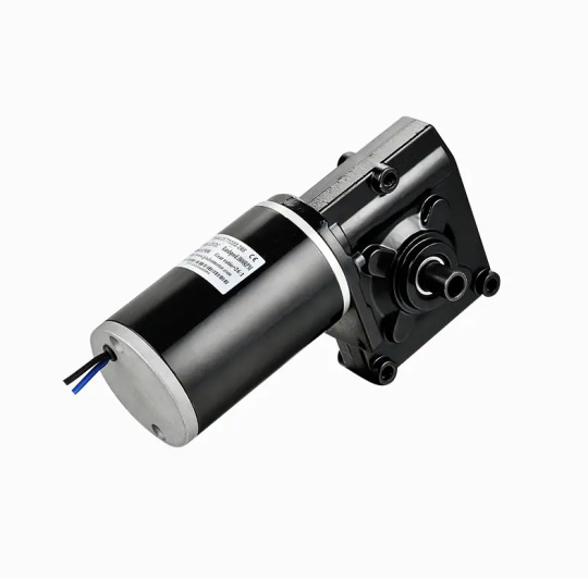
Exploring How the Speed of China DC Brushed Motor Can Be Effectively Controlled
The China DC Brushed Motor remains a widely used electromechanical component in various industries due to its cost-effectiveness, simplicity, and reliability. From small household appliances to industrial machines, these motors offer a straightforward solution for motion control. A critical aspect of their functionality lies in speed regulation. Whether for precision devices or variable-speed tools, controlling motor speed efficiently is essential. This article delves into the common methods used to manage the speed of a China DC Brushed Motor and how each technique impacts performance.
Voltage Control Method
One of the basic and direct ways to adjust the speed of a DC brushed motor is by varying the applied voltage. Since motor speed is nearly proportional to the supply voltage, increasing the voltage results in a higher rotational speed, while decreasing it slows the motor down. This method is simple and effective, especially in low-cost systems. However, it offers limited precision and may affect torque output and efficiency at lower voltages. Additionally, voltage drops under load can cause speed instability, making this approach less suitable for applications requiring consistent performance.
Pulse Width Modulation (PWM)
PWM is the commonly used method for precise speed control in a China DC Brushed Motor. Instead of reducing voltage directly, this technique turns the power on and off rapidly using electronic switches. By adjusting the duty cycle—the proportion of time the power is "on" during each cycle—PWM effectively controls the average voltage supplied to the motor. This allows for highly efficient speed modulation without significant power loss or heat generation. PWM also enables smoother acceleration and deceleration and is widely supported by microcontrollers and motor drivers, making it ideal for modern automation systems.
Closed-Loop Feedback Control
For applications where stable and accurate speed is critical, closed-loop systems are used. These systems integrate sensors, such as encoders or tachometers, that continuously monitor the motor’s speed and provide real-time feedback to a controller. The controller compares the actual speed to the desired value and adjusts the input (often via PWM) accordingly. This setup compensates for load changes or supply fluctuations and ensures consistent performance. Though more complex and costly, closed-loop control offers high precision and is frequently employed in robotics, CNC machines, and other demanding environments using China DC Brushed Motors.
Resistive Speed Control (Less Common Today)
In the past, series resistors were often used to drop voltage and thereby reduce motor speed. While still occasionally seen in low-tech or educational applications, this method is inefficient, as the resistor dissipates energy as heat. It also causes voltage instability under load and provides poor control resolution. As such, resistive methods are now largely obsolete compared to PWM and electronic controllers.
Digital Motor Controllers
Modern digital controllers bring together advanced techniques for controlling China DC Brushed Motors. These systems often combine PWM modulation, feedback loops, and interface options for programmable speed settings. Some even support communication protocols like CAN, UART, or I²C, allowing for integration into larger embedded systems. These controllers not only enhance speed control accuracy but also improve safety, protection, and diagnostics.
Conclusion
Controlling the speed of a China DC Brushed Motor involves a range of techniques, from simple voltage adjustments to advanced PWM and closed-loop systems. Each method has its strengths and trade-offs, with the choice depending on application requirements such as cost, precision, and energy efficiency. As technology evolves, smarter and more integrated control systems continue to expand the versatility of these reliable motors, ensuring their relevance across both traditional and modern industries.
Performance Highlights: Output Speed and Torque: The motor offers a versatile range of speed and torque options, allowing for customization to suit specific application requirements. The gearbox provides precise control over speed and torque output. Efficiency: With its brushed DC technology and precision gearbox, this motor delivers high efficiency, minimizing energy consumption and heat generation. Reliability: The 7712Z motor is designed for continuous operation with minimal wear and tear, ensuring a reliable performance over an extended lifespan.
0 notes