#flash download tool for esp32
Explore tagged Tumblr posts
Visit Tumblr Blog
Explore Tumblr blogs with no restrictions, modern design and the best experience.
Last Seen Tumblr Blogs


Fun Fact
The KCSC sent more than 20K requests to delete posts related to prostitution and porn to Tumblr from January to June 2017.
Text
ESP32 Daten als CSV exportieren: Einfacher Zugriff über den Webbrowser

In diesem Beitrag zeige ich dir, wie du die Verbrauchsdaten eines Shelly-Geräts auf einem ESP32-C3 Mikrocontroller speichern und anschließend bequem per REST-Schnittstelle als CSV-Datei exportieren kannst. Im vorangegangenen Beitrag „Shelly 1PM + ESP32: Daten speichern & zeitgesteuert senden“ habe ich bereits erläutert, wie sich die Messwerte lokal sichern und automatisch an ThingSpeak übertragen lassen. Nun erweitern wir das Projekt um eine einfache und praktische Möglichkeit zur lokalen Datenweitergabe per Webbrowser. https://youtu.be/S2qRoNZroCY Ein Leser hat daraufhin die sinnvolle Idee eingebracht, die gespeicherten Daten zusätzlich als CSV-Datei verfügbar zu machen – zum Beispiel für die Weiterverarbeitung in Excel oder zur lokalen Archivierung.
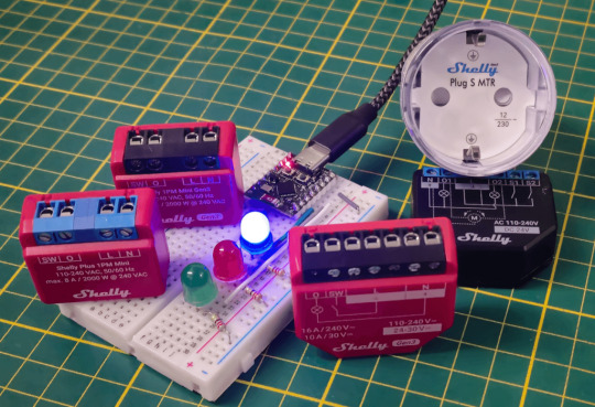
ESP32-C3 Super Mini mit Shelly PMs und Plug S In diesem Beitrag zeige ich dir, wie du genau das umsetzen kannst: Der ESP32 stellt über einen kleinen integrierten Webserver die erfassten Messwerte als CSV-Datei zum Download bereit. So kannst du bequem über deinen Browser auf die Daten zugreifen – ganz ohne zusätzliche Tools oder Cloud-Zwang.
Rückblick - Aufzeichnen der Daten auf dem Mikrocontroller
Die vom Shelly gelieferten Messdaten (Spannung, Strom, Leistungsaufnahme) werden über die integrierte REST-Schnittstelle regelmäßig vom ESP32-C3 Mikrocontroller abgefragt und lokal im Flash-Speicher gesichert. Die Speicherung erfolgt im JSON-Format, strukturiert nach Datum und Zeitstempel, sodass die Daten später einfach verarbeitet oder exportiert werden können – auch bei fehlender Internetverbindung. 👉 Tipp: Eine ausführliche Schritt-für-Schritt-Anleitung zum Aufbau, zur Programmierung und zur Datenspeicherung findest du in meinem Beitrag: „Shelly 1PM + ESP32: Daten speichern & zeitgesteuert senden“. Datenarchiv für 5 Tage – Speicher automatisch verwalten Um eine längere Verfügbarkeit der Daten zu gewährleisten, werden die erfassten Werte nun nicht mehr direkt nach dem Upload an ThingSpeak gelöscht. Stattdessen bleiben sie für maximal 5 Tage auf dem Mikrocontroller gespeichert. So kannst du die Daten zusätzlich als CSV-Datei im Browser abrufen oder lokal sichern – auch nachträglich. Außerdem wurde das Messintervall von 5 auf 15 Minuten angepasst, um den Speicherverbrauch pro Tag zu reduzieren. Bei einem Intervall von 15 Minuten entstehen ca. 96 Datensätze pro Tag, was selbst bei mehreren Tagen gut in den internen 4 MB Flash-Speicher passt. Die Datensätze werden nun täglich geprüft: Ist ein Datumseintrag älter als 5 Tage, wird dieser automatisch gelöscht. So bleibt der Speicherplatz effizient verwaltet, und du erhältst trotzdem eine kurze Historie deiner Energiedaten – ohne manuelles Eingreifen.
Auslesen der JSON-Daten vom Mikrocontroller
Wie bereits erwähnt, werden die erfassten Messdaten auf dem Mikrocontroller im JSON-Format gespeichert. Es gibt mehrere Möglichkeiten, diese Daten auszulesen. Die einfachste Methode besteht darin, die Datei direkt über die Entwicklungsumgebung Thonny vom Mikrocontroller auf den PC zu kopieren. Dazu ist allerdings eine aktive Verbindung über ein USB-Datenkabel erforderlich – was in manchen Szenarien nicht möglich oder praktisch ist. Eine clevere Alternative bietet eine einfache REST-Schnittstelle, die wir mit wenigen Zeilen Code selbst einrichten können. Das ist einer der vielen Vorteile von MicroPython: Es ermöglicht uns, schnell einen kleinen Webserver zu realisieren, über den wir die Daten bequem per Browser abrufen können – ganz ohne physische Verbindung.
Schaltung am ESP32-C3
Im Grunde benötigt man keine zusätzliche Schaltung denn es spielt sich alles ohne zusätzliche Komponenten ab. Jedoch habe ich drei LEDs angeschlossen um den aktuellen Zustand zu visualisieren.
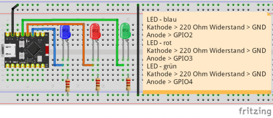
Schaltung - ESP32-C3 mit LEDs - Eine blaue LED für die aktive WiFi-Verbindung. - Eine rote LED für eventuelle Fehler. - Eine grüne LED als indikator für abruf der Daten vom Shelly.
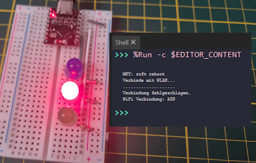
ESP32-C3 - Fehler keine WiFi-Verbindung
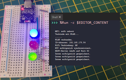
ESP32-C3 erfolgreicher Abruf der Daten
Programmieren einer REST-Schnittstelle in MicroPython
In diesem Abschnitt programmieren wir die REST-Schnittstelle direkt auf dem ESP32 in MicroPython. Ziel ist es, zwei zentrale UseCases abzubilden: - Download der Messdaten als CSV-Datei – zur einfachen Weiterverarbeitung z. B. in Microsoft Excel oder ähnlichen Anwendungen. - Bereitstellung der Rohdaten im JSON-Format – ideal für Entwickler, APIs oder Tools, die die Daten maschinell weiterverarbeiten möchten. Beide Varianten sind über den Webserver bequem über den Browser abrufbar – lokal, ohne Cloud-Anbindung, und ohne zusätzliche Software.

Ausgabe der gespeicherten Daten im JSON-Format

download der Daten als CSV-Datei vom ESP32-C3 Der Download der CSV-Datei funktioniert besonders komfortabel: Der Chrome-Browser bietet die Datei beim Aufruf der entsprechenden URL direkt zum Speichern an – ganz ohne zusätzliches Zutun. Alles, was wir im Code tun müssen, ist, die CSV-Daten korrekt an den Client zu senden. Der Browser übernimmt den Rest automatisch. Ich habe dir den Code bereits im Beitrag Shelly 1PM + ESP32: Daten speichern & zeitgesteuert senden ausführlich vorgestellt, hier soll es lediglich um die REST-Schnittstelle gehen. Du findest im nächsten Kapitel jedoch den kompletten Quellcode als ZIP-Datei zum download. Schritt 1 - initialisieren des Servers Da wir bereits eine aktive WiFi-Verbindung haben, können wir direkt mit der Initialisierung des Servers starten. Das Gute ist, das MicroPython dafür alles mitbringt und wir hier keine Zusätzlichen Module installieren müssen (wir müssen diese lediglich im Code importieren). # Module für Netzwerk, Datenverarbeitung und Zugriff auf gespeicherte Daten import socket import ujson import datastore import util import logger from configuration import REST_SERVER_PORT # Initialisiert den REST-Server auf dem angegebenen Port (Standard: 80) def init_rest_server(port=REST_SERVER_PORT): addr = socket.getaddrinfo('0.0.0.0', port) # Ermittelt die Adresse s = socket.socket() # Erstellt einen TCP-Socket s.bind(addr) # Bindet den Socket an die Adresse s.listen(1) # Wartet auf Verbindungen (max. 1 gleichzeitig) s.setblocking(False) # Setzt den Socket auf nicht-blockierend (wichtig für Main-Loop) logger.debugLog(f'REST-Server läuft auf Port {port}') return s Schritt 2 - Anfragen akzeptieren und senden der Daten Die nächste Funktion beinhaltet das akzeptieren einer Anfrage vom Client und das senden der Daten. parse_http_request(request) – HTTP-Anfrage analysieren Diese Funktion extrahiert aus der ersten Zeile der eingehenden HTTP-Anfrage die HTTP-Methode (z. B. GET) sowie den angeforderten Pfad (z. B. /data?format=csv). So wissen wir, auf welche Ressource zugegriffen werden soll. def parse_http_request(request): try: request_line = request.split('rn') method, path, _ = request_line.split() return method, path except: return None, None get_format_from_path(path) – Ausgabeformat bestimmen (JSON oder CSV) Hier wird geprüft, ob in der URL ein format=-Parameter übergeben wurde. Falls ja, wird das gewünschte Format zurückgegeben – standardmäßig ist json voreingestellt. Beispiel: /data?format=csv → Ausgabe als CSV-Datei. def get_format_from_path(path): format_type = "json" if '?' in path: query = path.split('?') params = query.split('&') for p in params: if '=' in p: key, value = p.split('=') if key == 'format': format_type = value.lower() return format_type respond_with_csv(client, data) – CSV-Antwort an den Client senden Diese Funktion übernimmt den CSV-Export: Die Daten werden in CSV umgewandelt und mit den passenden HTTP-Headern an den Client zurückgeschickt. Browser wie Chrome starten bei Content-Type: text/csv automatisch den Dateidownload. def respond_with_csv(client, data): csv_data = util.dict_to_csv(data) client.send("HTTP/1.1 200 OKrn") client.send("Content-Type: text/csvrn") client.send("Access-Control-Allow-Origin: *rn") client.send("Connection: closernrn") client.send(csv_data) respond_with_json(client, data) – JSON-Daten senden Hier werden die Daten als JSON an den Client gesendet. Das ist besonders hilfreich für Entwickler, APIs oder Automatisierungsskripte, die die Rohdaten weiterverarbeiten möchten. def respond_with_json(client, data): json_data = ujson.dumps(data) client.send("HTTP/1.1 200 OKrn") client.send("Content-Type: application/jsonrn") client.send("Access-Control-Allow-Origin: *rn") client.send("Connection: closernrn") client.send(json_data) handle_rest_request(server) – REST-Endpunkt zentral verarbeiten Dies ist die Hauptfunktion, die die REST-Schnittstelle steuert. Sie akzeptiert eingehende Verbindungen, wertet die Anfrage aus, lädt die Daten und entscheidet anhand des Formats, ob JSON oder CSV gesendet werden soll. Für ungültige Pfade wird eine einfache 404-Meldung zurückgegeben. def handle_rest_request(server): try: client, addr = server.accept() except OSError: return try: request = client.recv(1024).decode('utf-8') method, path = parse_http_request(request) if method == 'GET' and path.startswith('/data'): format_type = get_format_from_path(path) data = datastore.read_json_file() if format_type == 'csv': respond_with_csv(client, data) else: respond_with_json(client, data) else: client.send("HTTP/1.1 404 Not Foundrn") client.send("Content-Type: text/plainrnrn") client.send("Seite nicht gefunden.") except Exception as e: logger.debugLog(f"Fehler beim Verarbeiten: {e}") finally: client.close()
Quellcode zum Abrufen der Daten vom ESP32 via REST-Schnittstelle
Den Quellcode habe ich in mehrere Dateien aufgeteilt und so deutlich übersichtlicher gestaltet. - main.py => Hauptprogramm - wifi.py => Aufbau der WiFi-Verbindung - datastore.py => Funktionen zum Daten vom Mikrocontroller zu lesen und zu speichern - led.py => LEDs steuern (WiFi, Fehler, Datenabruf) - logger.py => Datenlogger für Fehler-/Infomeldungen - util.py => Hilfsfunktionen für das Programm (Datumformatieren, etc.) - configuration.py => Werte für die WiFi-Verbindung, Server-Port, etc. fertiges Programm zum speichern von Daten eines Shellys auf dem ESP32-C3 und abrufen via REST-SchnittstelleHerunterladen Quellcode - main.py # Standardbibliothek für Zeitfunktionen import time # Eigene Module import wifi # WLAN-Verbindung herstellen import led # LEDs zur Statusanzeige import fetchShellyData as shelly # Modul zum Abrufen von Shelly-Daten via HTTP import util # Hilfsfunktionen, z. B. zum Parsen der Daten oder RTC-Sync import logger # Debug-Logging import datastore # Daten lokal speichern/verwalten import machine # MicroPython-Hardwarefunktionen (z. B. Reset, Pin, etc.) import server as restServer # REST-API-Modul zum Bereitstellen von Daten # Zeitintervall zwischen zwei Datenabrufen (in Millisekunden) from configuration import FETCH_INTERVAL_MS # Zeitpunkt des letzten Abrufs merken letzter_aufruf = time.ticks_ms() # Aufgabe: Daten vom Shelly holen, aufbereiten und speichern def fetchData_task(): data = shelly.fetch_shelly_data() # Rohdaten vom Shelly abfragen (HTTP GET) shellyData = util.extract_shelly_values(data) # Wichtige Werte extrahieren (current, voltage, apower) led.receivedDataLED() # LED blinkt kurz zur Bestätigung des Dateneingangs datastore.read_json_file() # Vorherige Daten aus Datei laden datastore.remove_old_entries() # Alte Einträge ggf. löschen (z. B. > 5 Tage alt) datastore.add_entry(shellyData) # Aktuelle Daten hinzufügen datastore.save_data_to_file() # Daten wieder in Datei speichern # Hauptprogramm try: led.setErrorLED(False) # Fehler-LED ausschalten led.setWiFiActive(False) # WiFi-LED ebenfalls deaktivieren (wird gleich gesetzt) isWiFiConnected = wifi.connect_wifi() # Mit WLAN verbinden logger.debugLog('WiFi Verbindung: '+ ('AN' if isWiFiConnected else 'AUS')) if isWiFiConnected: if util.sync_rtc(): # Systemzeit mit NTP synchronisieren server = restServer.init_rest_server() # REST-API initialisieren while True: restServer.handle_rest_request(server) # HTTP-Anfragen bearbeiten jetzt = time.ticks_ms() # Aktueller Zeitstempel if time.ticks_diff(jetzt, letzter_aufruf) >= FETCH_INTERVAL_MS: fetchData_task() # Nur alle 5 Sekunden Daten abrufen letzter_aufruf = jetzt else: led.setErrorLED(True) # RTC-Sync fehlgeschlagen → Fehler anzeigen else: led.setErrorLED(True) # WLAN-Verbindung fehlgeschlagen → Fehler anzeigen led.setWiFiActive(False) # WLAN-LED am Ende wieder deaktivieren except Exception as e: led.setErrorLED(True) # Fehler-LED einschalten bei unerwartetem Fehler print(e) # Fehlerausgabe zur Analyse Quellcode - wifi.py # Importiere Netzwerksteuerung für WLAN import network import time import led from configuration import WIFI_SSID as SSID, WIFI_PASSWORD as PASSWORD # WLAN-Zugangsdaten (→ solltest du später z. B. in eine separate config.py auslagern) SSID = "FRITZBox7590GI24" PASSWORD = "22894580214767401850" # Verbindet das Gerät mit dem WLAN-Netzwerk def connect_wifi(): global SSID, PASSWORD # WLAN-Schnittstelle im Station-Modus (STA_IF = Client-Modus) wlan = network.WLAN(network.STA_IF) wlan.active(True) # Aktiviert WLAN # Wenn noch keine Verbindung besteht, versuche zu verbinden if not wlan.isconnected(): print("Verbinde mit WLAN...") wlan.connect(SSID, PASSWORD) # Warte auf Verbindung (max. 10 Sekunden) timeout = 10 # Sekunden while not wlan.isconnected() and timeout > 0: led.blink(0.25) # Status-LED blinkt während Verbindungsversuch timeout -= 0.5 print(".", end="") # Ausgabe eines Punkts pro Versuch (optional) # Ergebnis prüfen if wlan.isconnected(): print("nWLAN verbunden.") print("IP-Adresse:", wlan.ifconfig()) # Ausgabe der zugewiesenen IP-Adresse led.setWiFiActive(True) # WLAN-LED einschalten return True else: print("nVerbindung fehlgeschlagen.") led.setWiFiActive(False) # WLAN-LED ausschalten return False Quellcode - datastore.py # JSON-Verarbeitung und Logging import ujson import logger import util from configuration import DATASTORE_FILENAME as filename # Globale Datenstruktur zum Zwischenspeichern der Daten im RAM data = {} # Liest die JSON-Datei ein und lädt sie als Dictionary in die globale Variable `data` def read_json_file(): global data, filename try: with open(filename, 'r') as file: data = ujson.load(file) # Inhalt der Datei in `data` laden return data except OSError: logger.debugLog(f"Datei '{filename}' wurde nicht gefunden.", "ERROR") except ValueError: logger.debugLog(f"Fehler beim Einlesen der Datei '{filename}': Ungültiges JSON-Format.","ERROR") # Fügt einen neuen Messwert in die Datenstruktur ein def add_entry(values_dict): global data # Extrahiere Datum im Format DD.MM.YYYY und Zeitstempel (Unixzeit) timestamp_str = values_dict date_str = util.timestamp_to_date(values_dict) # Wenn der Tag noch nicht im Dictionary ist, anlegen if date_str not in data: data = {} # Entferne den Zeitstempel aus dem Dictionary der Messwerte (ist schon im Key enthalten) values_dict.pop('unixtime') # Werte unter dem entsprechenden Datum und Zeitstempel speichern data = values_dict # Speichert die globale `data`-Struktur als JSON-Datei def save_data_to_file(): global data, filename try: with open(filename, "w") as file: ujson.dump(data, file) # Schreibe Daten in Datei logger.debugLog("Daten erfolgreich gespeichert.") except OSError as osError: logger.debugLog("Fehler beim Schreiben der Datei. Read the full article
0 notes
Text
Flash Download Tool como Gravar Binários no ESP32
Este post é um tutorial de como gravar binários no ESP32 usando a Flash Download Tool disponibilizado pela Espressif.
Flash Download Tool é uma ferramenta disponibilizado pela Espressif para exportar arquivos binários para o ESP32. Baixar e instalar Flash Download Tool Antes de tudo é necessário baixar o programa Flash Download Tool no site de Espressif, após baixar, abra e defina chipType como ESP32. Além disso, haverá outras configurações mas não serão necessárias, por ultimo click ‘ok���. Entendendo o Flash…
Ver no WordPress
#download flash tool exe#esp 32#esp32 arduino#esp32 arduino ide#esp32 board#esp32 bootloader#esp32 flash download tool command line#esp32 wroom#esp8266 flash download tool#espressif esp32 flash download tool#flash download tool esp32#flash download tool for esp32#flash download tools#flash download tools (esp8266 e esp32 & esp32-s2)#usb flash download tool
0 notes
Text
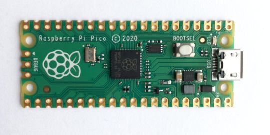
A Peek at the Pico, Raspberry Pi's Newest Petite Powerhouse
Raspberry Pi Pico
8.80 / 10
Read Reviews
Read More Reviews
Read More Reviews
Read More Reviews
Read More Reviews
Read More Reviews


Shop Now
Meet the new Raspberry Pi Pico; a tiny microcontroller filled with big possibilities.
Specifications
Brand: Raspberry Pi
CPU: Dual-core 133Mhz ARM
Memory: 264Kb
Ports: microUSB
Pros
Powerful ARM Processor
Micro-USB Connectivity
Breadboard Mountable
Easy-To-Use Interface
Absolutely Adorable
Inexpensive
Cons
No Wi-Fi or Bluetooth connectivity
No Header Pins
I/O Port Labelling on One Side Only
No USB-C Connectivity
Buy This Product
Raspberry Pi Pico other
Shop
// Bottom var galleryThumbs1 = new Swiper('.gallery-thumbs-1', { spaceBetween: 10, slidesPerView: 10, freeMode: true, watchSlidesVisibility: true, watchSlidesProgress: true, centerInsufficientSlides: true, allowTouchMove: false, preventClicks: false, breakpoints: { 1024: { slidesPerView: 6, } }, }); // Top var galleryTop1 = new Swiper('.gallery-top-1', { spaceBetween: 10, allowTouchMove: false, loop: true, preventClicks: false, breakpoints: { 1024: { allowTouchMove: true, } }, navigation: { nextEl: '.swiper-button-next', prevEl: '.swiper-button-prev', }, thumbs: { swiper: galleryThumbs1 } });
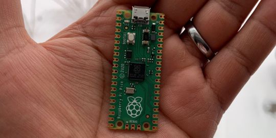
We’ve managed to get our hands on the coveted Raspberry Pi Pico. Today, we’re going to be looking at some of the most important features and putting it toe-to-toe with some of the biggest names in small electronics.
We’ll be showing you what the Pico can do, and we’ll get you started with MicroPython, one of Pico’s supported programming languages. We’ll even offer up some code to try in case you decide to buy a Pico of your own.
What Is a Raspberry Pi Pico?
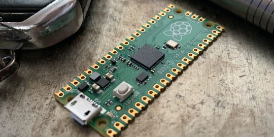
Raspberry Pi Pico is a new budget microcontroller designed by Raspberry Pi. It’s a tiny computer built around a single chip, with onboard memory, and programmable in/out ports. Historically, microcontrollers are used in a variety of devices from medical implants to power tools. If you have an electronic device sitting in your vicinity, there’s a good chance that there’s a microcontroller inside of it.
Key Features of the Pico

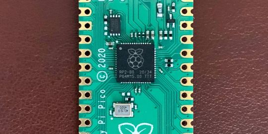
The Pico is built around the RP2040 microcontroller chip, which was designed by Raspberry Pi UK. It’s a Dual-Core ARM processor with a flexible clock that can run up to 133 MHz. The Pico also supports 1.8-5.5 DC input voltage, has a micro-USB input port, and an onboard temperature sensor.
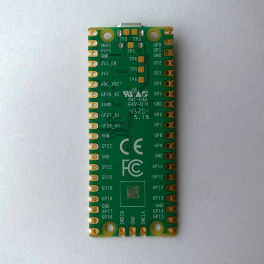
Flanking the chip on all sides are a series of castellations that allow easy soldering to a Veroboard or breadboard. This dual in-line package (DIP) style form factor is stackable, and can also be used in carrier board applications.
Technical Specifications
21 mm x 51 mm
264kb on-chip RAM
2 MB on-board QSPI flash
2 UART
26 GPIO
2 SPI controllers
2 ISC controllers
16 PWM channels
Accelerated integer and floating-point libraries
3-pin ARM Serial Wire Debug (SWD) port
What’s So Special About the Pi Pico?
The Pi Pico is a different kind of microcontroller. It’s Raspberry Pi’s first, and it features ARM technology in its RP2040 silicon chip. Many technology companies are embracing silicon ARM chips, with major manufacturers like Apple leading the charge.
The punchy little Pico packs a staggering 26 multifunction general purpose input/output (GPIO) ports, including 3 that are analog. Alongside these ports are 8 programmable input/output (PIO) ports. Compare this to other microcontrollers like the Arduino Nano, and the Pico packs roughly 18% more GPIO capability.
The most considerable difference between the Pico and its competitors, however, is the $4 price tag. Low cost is the main selling point of this unique offering.
At launch, many online retailers sold out of the device due to the interest and Raspberry Pi’s favorable reputation. By setting the price so low, the Pico opens the door for a new class of high-powered, budget microcontrollers.
There are many potential applications for the new Pico. With its onboard temperature sensor, the device is an obvious choice for IoT projects.
One talented retro gaming enthusiast even used a Pico to build a gaming console with full VGA video support.
youtube
This means that makers who have been curious about Raspberry Pi, or microcontrollers in general, now have the ability to experiment for less than the price of a fancy cup of coffee.
Related: The Raspberry Pi Comes of Age With the Pi 400 Desktop
The Raspberry Pi Pico Processor
The RP2040 ARM chip is an interesting choice for the Pico. At 133MHz, the chip is capable of leaving more expensive boards, like the Arduino Uno, in the dust.
Using ARM processors seems to be an emerging trend in the world of microcontrollers. In addition to Raspberry Pi, both Sparkfun and Adafruit also offer boards with similar ARM technology.
The industry-wide switch was made for a single reason—speed. ARM processors give a considerable boost over standard Atmel chips. In a board this size, using an ARM processor is like dropping a fully kitted Porsche engine into a Volkswagen. On the other hand, many microcontrollers don’t require that much processing speed. Yet.
Ramping up performance means that makers who want to push the limits of the Pico will have an abundance of power to do so.
The I/O Ports
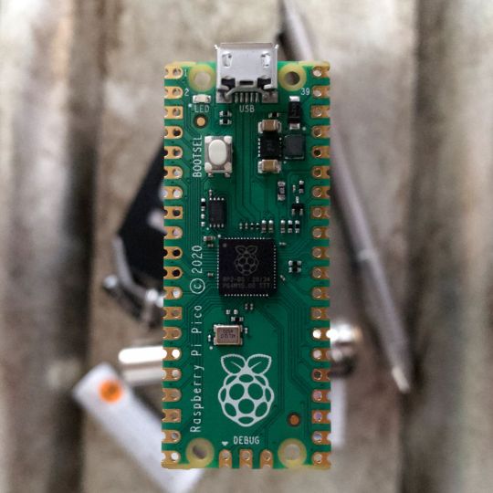
The GPIO ports on the Pi Pico feature several interesting functions for common uses such as operating a screen, running lighting, or incorporating servos/relays. Some functions of the GPIO are available on all ports, and some only work for specific uses. GPIO 25, for example, controls the Pico’s onboard LED, and GPIO 23 controls the onboard SMPS Power Save feature.
The Pico also has both VSYS (1.8V — 5.5V) and VBUS (5V when connected to USB) ports, which are designed to deliver current to the RP2040 and its GPIO. This means that powering the Pico can be done with or without the use of the onboard micro-USB.
A full list of the I/O ports is available on Raspberry Pi’s website in its complete Pico documentation.
Pico vs. Arduino vs. Others
One question on the minds of many makers is whether or not the Raspberry Pi Pico is better than Arduino?
That depends. Pound-for-pound, higher-end Arduino boards like the Portenta H7 make the Pico look like a toy. However, the steep cost for a board of that caliber might be a tough pill for the microcontroller hobbyist to swallow. That's why the smaller price tag on the Pico makes it a win for makers who enjoy low-risk experimentation.
Along with minimal cost, the Raspberry Pi jams an extensive feature set into the Pico, comparable to boards like the Teensy LC, and the ESP32. But neither of these competitors manage to challenge the budget-friendly Pico on price.
That's what makes the Pico such a fantastic value, and a great choice for hobbyists and power users alike.
The Pi Pico: What’s Not To Love?
Unfortunately, to drive the price of the Pico down, Raspberry Pi had to make a few compromises. The most notable of which is the lack of an onboard radio module. Neither Bluetooth nor Wi-Fi is supported without add-ons.
The Wi-Fi limitation can be eliminated by adding a module like the ESP-01. Bluetooth support may prove a bit more challenging. If you need an all-in-one solution for your products, you’re better off skipping the Pico, and spending a little extra for something like the Pi Zero W, or ESP32.
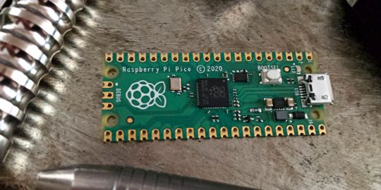
Additionally, many early adopters are complaining about the lack of GPIO labeling on the top of the board. Raspberry Pi provides an extensive amount of documentation on its website to address this, but pointing-and-clicking, or thumbing through paperwork when you have a hot soldering iron in your hands isn’t often desirable.
Lastly, the lack of I/O pin headers is something of an issue for some, as it means less convenience when swapping I/O components. This minor annoyance can be solved via the use of leads, soldering the component wiring directly to the Pico, or using a breadboard.
If you’ve been using microcontrollers or small electronics for any period of time, then an unpopulated board is most likely a non-issue. Of course, you could also add your own pin headers if you plan on regular experimentation with different external components.
The final rub with the Pico is the micro-USB port. With many other microcontrollers like the Portenta H7 moving toward USB-C, Raspberry Pi's micro-USB port seems dated.
Logically however, the decision to use micro-USB makes sense. It was done by Raspberry Pi to keep costs as low as possible, and to keep interface capability almost universal. Everyone we know has at least a few micro-USB cables tucked away somewhere in their homes.
However, with future versions, a USB-C interface would be a nice addition to an already spectacular package.
Related: A Beginners Guide To Breadboarding With Raspberry Pi
Programming the Raspberry Pi Pico
Interfacing with the Pi Pico can be done via C/C++, or via MicroPython in the Read-Eval-Print-Loop or REPL (pronounced “Reh-pul”). The REPL is essentially a command line interface that runs line-by-line code in a loop.
In order to access the REPL, you’ll need to install MicroPython onto the Pico. This process is simple and only involves four steps.
Installing MicroPython
Download MicroPython for Raspberry Pi Pico from the Raspberry Pi Website
Connect the Pico to your computer via micro-USB while holding the BOOTSEL button
Wait for the Pico to appear as an external drive
Copy the MicroPython file to the Pi Pico, and it will automatically reboot
You can access the REPL in a number of ways. We used the screen command in a macOS terminal window to access the serial bus connected to the Pico. To accomplish this with Terminal, you’ll first open a new terminal window, then type ls /dev/tty*
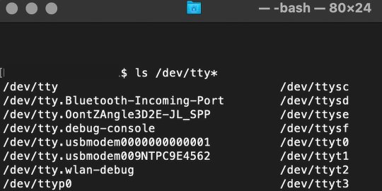
From there, find the port where the Pico is connected. It should be labeled something like /dev/tty.usbmodem0000000000001. Then run the command:
screen /dev/tty.usbmodem0000000000001
Your cursor should change. Hit Return and the cursor will change again to >>>.
In the image below we've included the classic Hello World (Hello, Pico) command-line program in the REPL, along with a few lines of code that will turn the Pico's LED on and off. Feel free to try them yourself.
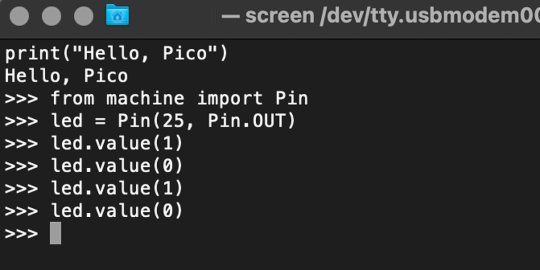
For more information, we recommend you invest in the official starter guide to MicroPython that Raspberry Pi has published on their website.
Download: MicroPython for Raspberry Pi Pico (free)
Using the Raspberry Pi Pico With Thonny
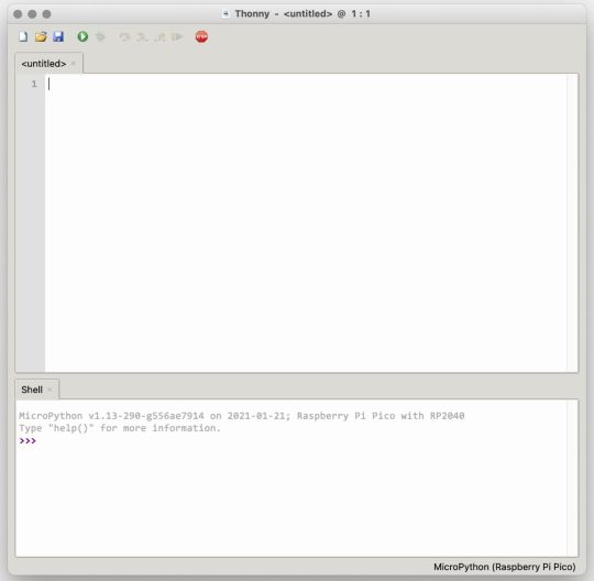
If you’re looking for a more proper coding environment, the Raspberry Pi Pico will also allow access to the REPL with Thonny. To enable this feature, first download and install Thonny. Once installed, connect your Pi Pico. Open Thonny and you'll see information indicating your Pico is connected in the Shell.
At the bottom right of the screen, you should see a version of Python. Click this version and select MicroPython (Raspberry Pi Pico) from the drop-down menu.
Now you can type commands into the Shell, or you can use Thonny’s editor to write or import multiple lines of code.
The abundance of interface possibilities make the Raspberry Pi Pico easy to program. For those who are familiar with MicroPython, this should be nothing new. For beginners, however, Thonny provides a powerful interface and debugger to get started with programming.
Download: Thonny (Free) Windows | Mac
Should I Buy the Raspberry Pi Pico?
The Raspberry Pi Pico is a powerful budget board that is perfect for hobbyists, or makers just starting out with microcontrollers. The documentation, low cost, and wide range of possibilities for the Pico also make it a great choice for seasoned small electronics wizards. If you’re a DIYer who loves to tinker, or you just want to challenge yourself to a weekend project, then you’ll love playing with the Pico.
On the other hand, if you don't have one or more projects in mind that need a microcontroller, then this board is probably not for you. Also, if your project needs Wi-Fi connectivity or Bluetooth, then the Pico won’t scratch that itch. And finally, for users who aren’t comfortable learning MicroPython, or exploring C/C++, the Pico isn't ideal. And remember: this Raspberry Pi is not like the others. It will not run a full Linux operating system.
But, if you dream in Python, or if you love the smell of solder, then you won't regret grabbing this tiny powerhouse. Most of all, if the sight of the sports-car-sleek RP2040 gets your creative gears turning, then we think you’ll really benefit from picking up the Pico.
Serving up Several Sweet Possibilities
While it isn’t perfect, the Raspberry Pi Pico is a strong entry into the world of microcontrollers. The reputation that Raspberry Pi has built for quality electronic components at a relatively low price extends to the Pico.
It’s everything a Raspberry Pi should be: small, sweet, and superb. It’s beautifully designed, and extremely inexpensive. But the best part isn’t the looks or the low cost.
The best part about this small wonder is picking it up, and holding it in your hands. It's feeling the tug of electronic inspiration. It's realizing just how powerful the Pico is, and what it means for microcontrollers going forward.
And truthfully, we think it's amazing that something as small as the Pico can offer so many unique possibilities.
A Peek at the Pico, Raspberry Pi's Newest Petite Powerhouse published first on http://droneseco.tumblr.com/
0 notes
Photo

[Amazon Web Services] ESP32-DevKitCにAmazon FreeRTOSをインストールする https://ift.tt/33JmN95
Amazon FreeRTOS(以下FreeRTOS)は様々なデバイスにインストールすることができエッジ側にAWSの環境を拡張する手段を提供しているが、ここでは手に入りやすいEspressif ESP32-DevKitC(以下ESP32)にFreeRTOSをインストールする手順を示す。
Espressif ESP32-DevKitC と ESP-WROVER-KIT の開始方法 (Amazon Web Services)
waves ESP32 DevKitC V4 ESP-WROOM-32 ESP-32 WiFi BLE 技適取得済 国内発送AMAZON JP
動作環境
FreeRTOSを使うにあたりあらかじめ以下をインストールしておく。
⦿ Pytyoh 2.7.10以降 (3.xでよいが、2.xを使う場面あり) ⦿ pip ⦿ AWS SDK for Python (boto3) ⦿ AWS CLI
$ python --version Python 3.6.8 $ python2 --version Python 2.7.15+ $ pip --version pip 19.3.1 from /usr/local/lib/python3.6/dist-packages/pip (python 3.6) $ pip list | grep boto3 boto3 1.9.253 $ aws --version aws-cli/1.16.263 Python/3.6.8 Linux/4.15.0-65-generic botocore/1.12.253
ツールチェーンインストール
まずEspressif公式サイトからUbuntu用のツールチェーンをダウンロードしてインストールする。
https://docs.espressif.com/projects/esp-idf/en/v3.1.5/get-started-cmake/linux-setup.html
�� 以下をダウンロード & インストール
xtensa-esp32-elf-linux64-1.22.0-80-g6c4433a-5.2.0.tar.gz
$ mkdir ~/esp $ cd ~/esp $ tar zxvf ~/Downloads/xtensa-esp32-elf-linux64-1.22.0-80-g6c4433a-5.2.0.tar.gz
⦿ 環境変数設定
export PATH="$PATH:$HOME/esp/xtensa-esp32-elf/bin"
⦿ バージョン確認
$ xtensa-esp32-elf-gcc --version xtensa-esp32-elf-gcc (crosstool-NG crosstool-ng-1.22.0-80-g6c4433a) 5.2.0 Copyright (C) 2015 Free Software Foundation, Inc. This is free software; see the source for copying conditions. There is NO warranty; not even for MERCHANTABILITY or FITNESS FOR A PARTICULAR PURPOSE.
CMakeインストール
次にFreeRTOSビルド用のCMakeをインストールする。
Amazon FreeRTOSではCMake 3.13以降がサポートされるが、Ubuntuのパッケージリポジトリには3.10しか用意されていないためCMake公式サイトからダウンロードしてインストールする。
https://cmake.org/download/
⦿ 以下をダウンロード & インストール
cmake-3.15.4-Linux-x86_64.tar.gz
$ mkdir ~/tmp $ cd ~/tmp $ tar zxvf ~/Downloads/cmake-3.15.4-Linux-x86_64.tar.gz $ sudo cp -r cmake-3.15.4-Linux-x86_64/{bin,doc,share} /usr/local
manファイルについては格納場所/usr/local/manが/usr/local/share/manへのシンボリックリンクのためmanファイルのみ以下のようにしてコピーする。
$ sudo cp -r cmake-3.15.4-Linux-x86_64/man /usr/local/share
⦿ バージョン確認
$ cmake --version cmake version 3.15.4
Amazon FreeRTOSダウンロード & 設定
ビルドの準備が整ったらAmazon FreeRTOS公式GitHubからソース一式をダウンロードする。
https://github.com/aws/amazon-freertos
$ cd ~/tmp $ git clone https://github.com/aws/amazon-freertos.git --recurse-submodules
次にセットアップスクリプト用の設定ファイルを編集する。
$ cd amazon-freertos/tools/aws_config_quick_start $ vi configure.json { "afr_source_dir":"../..", <----------- 上記ダウンロードディレクトリ(amazon-freertosディレクトリのフルパス) "thing_name":"$thing_name", <--------- ESP32に付けるThing Name "wifi_ssid":"$wifi_ssid", <----------- Wi-Fiネッ���ワークのSSID "wifi_password":"$wifi_password", <--- Wi-Fiネットワークの接続パスワード "wifi_security":"$wifi_security" <---- Wi-Fiネットワークのセキュリティタイプ }
設定ファイルが編集できたらセットアップスクリプトを実行する。
$ python SetupAWS.py setup
これによりAWS IoT上のリソースが自動的に作られ、リソース間の関連付けも行われる。
⦿ モノ(Thing)作成

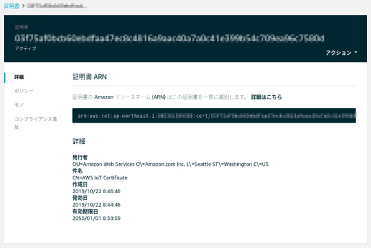
⦿ 証明書作成
⦿ ポリシー作成
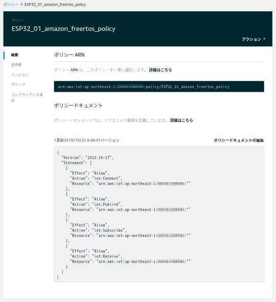
⦿ 証明書にポリシーをアタッチ
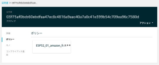
⦿ モノに証明書をアタッチ

⦿ 証明書関連のファイル作成
$ ls -l ESP32_01_* -r--r--r-- 1 xxx xxx 64 10月 22 08:46 ESP32_01_cert_id_file
⦿ MQTTエンドポイント、Wi-Fiネットワーク情報をデモ用aws_clientcredential.hファイルに追加
$ cat -n ../../demos/include/aws_clientcredential.h : 35 /* 36 * MQTT Broker endpoint. 37 */ 38 #define clientcredentialMQTT_BROKER_ENDPOINT "xxxxxxxxxxxxxx-ats.iot.ap-northeast-1.amazonaws.com" 39 40 41 /* Use of a "define" and not a "static const" here to be able to 42 * use pre-compile concatenation on the string. */ 43 #define clientcredentialIOT_THING_NAME "ESP32_01" : 56 /* 57 * Wi-Fi network to join. 58 */ 59 #define clientcredentialWIFI_SSID "xxxxxxxxxxxxxxxx" 60 61 /* 62 * Password needed to join Wi-Fi network. 63 */ 64 #define clientcredentialWIFI_PASSWORD "xxxxxxxxxxxxx" 65 66 /** 67 * @brief Security type 68 * WPA2 Security, @see WIFISecurity_t 69 * Possible values are - eWiFiSecurityOpen, eWiFiSecurityWEP, eWiFiSecurityWPA, 70 * eWiFiSecurityWPA2 71 */ 72 #define clientcredentialWIFI_SECURITY xxxxxxxxxxxxxxxxx 73 74 #endif
⦿ 証明書とプライベートキーをBase64エンコードしてデモ用
aws_clientcredential_keys.hファイルに追加
$ cat -n ../../demos/include/aws_clientcredential_keys.h : 29 /* 30 * PEM-encoded client certificate 31 * 32 * Must include the PEM header and footer: 33 * "-----BEGIN CERTIFICATE-----\n"\ 34 * "...base64 data...\n"\ 35 * "-----END CERTIFICATE-----\n" 36 */ 37 #define keyCLIENT_CERTIFICATE_PEM \ 38 "-----BEGIN CERTIFICATE-----\n"\ : 57 "-----END CERTIFICATE-----\n" 77 /* 78 * PEM-encoded client private key. 79 * 80 * Must include the PEM header and footer: 81 * "-----BEGIN RSA PRIVATE KEY-----\n"\ 82 * "...base64 data...\n"\ 83 * "-----END RSA PRIVATE KEY-----\n" 84 */ 85 #define keyCLIENT_PRIVATE_KEY_PEM \ 86 "-----BEGIN RSA PRIVATE KEY-----\n"\ : 112 "-----END RSA PRIVATE KEY-----\n" :
FreeRTOSデモプロジェクトビルド & ESP32書き込み & 実行
設定が終わったのでCMakeでFreeRTOSをビルドし、ESP32に書き込んで実行する。
⦿ ビルド
$ cd ../.. $ cmake -DVENDOR=espressif -DBOARD=esp32_devkitc -DCOMPILER=xtensa-esp32 -S . -B build $ cd build $ make all -j4 : [100%] Built target app
⦿ ESP32書き込み
ここでESP32をホストPCに接続し、まず以下を実行してESP32の中身を消去する。
$ cd .. $ ./vendors/espressif/esp-idf/tools/idf.py erase_flash -B build ESP-IDF currently only supports Python 2.7, and this is Python 3.6.8. Search for 'Setting the Python Interpreter' in the ESP-IDF docs for some tips to handle this.
ただ当該環境ではPython3がデフォルトなので上記のエラーになる。
idf.pyを書き換えてPython2を明示的に指定して再度実行する。
$ vi ./vendors/espressif/esp-idf/tools/idf.py (変更前) #!/usr/bin/env python (変更後) #!/usr/bin/env python2 $ ./vendors/espressif/esp-idf/tools/idf.py erase_flash -B build Setting IDF_PATH environment variable: ... : Chip erase completed successfully in 3.8s Hard resetting via RTS pin... Done
続いてFreeRTOSをESP32に書き込む。
$ cd build $ make flash [ 0%] Built target blank_ota_data [ 1%] Built target partition_table [ 1%] Built target idf_component_ulp : Wrote 953520 bytes (585067 compressed) at 0x00020000 in 14.5 seconds (effective 526.8 kbit/s)... Hash of data verified. Leaving... Hard resetting via RTS pin... [100%] Built target flash
⦿ AWS上のMQTTメッセージのモニタリング
AWS IoTコンソールでMQTTクライアントを使ってESP32がAWSに送信するメッセージをサブスクライブしておく。
[テスト]をクリックするとMQTTクライアントが開くので[トピックのサブスクリプション]フィールドに「iotdemo/#」と入力して[トピックへのサブスクラ…]をクリックする。

いまサブスクライブしたトピックの[iotdemo/#]をクリックしてメッセージを待ち受ける。

⦿ デモプログラム実行
この状態でデモプログラムを実行するとMQTTでパブリッシュが行われ、AWS IoTコンソール上でもメッセージが受信できていることが確認できる。
$ cd .. $ ./vendors/espressif/esp-idf/tools/idf.py monitor -p /dev/ttyUSB0 -B build : 157 914 [iot_thread] [INFO ][DEMO][9140] Demo completed successfully. 158 918 [iot_thread] [INFO ][INIT][9180] SDK cleanup done. 159 918 [iot_thread] [INFO ][DEMO][9180] -------DEMO FINISHED------- -> Ctrl + ]で終了

参考サイト
AWS IoT情報 (Qiita)
元記事はこちら
「[Amazon Web Services] ESP32-DevKitCにAmazon FreeRTOSをインストールする 」
November 13, 2019 at 12:00PM
0 notes
Text
Polish company Husarion launched CORE2 — its second generation robot hardware controller for rapid prototyping and development. CORE2 is compatible with ROS, relies on an RTOS-based open-source software framework, and can be programmed with free tools either via cloud or offline. The controller is also compatible with other building platforms such as LEGO Mindstorms or Makeblock via optional modules.
CORE2 and CORE2-ROS boards side by side | Image credit: Husarion
CORE2 was showcased earlier this year at the Hannover Messe trade fair, and just like previous generation it is part of Husarion’s robotic development platform which is focused on making robot building more accessible for everyone.
What can Husarion CORE2 do?
CORE2 comes in two flavors. There’s the standalone low-power real-time connected computer with on-board ESP32 WiFi module for energy efficient or cloud-based projects.
Robot Operating System
CORE2-ROS harvests the processing power of an attached single-board computer such as the Raspberry Pi 3 or ASUS Tinker Board, while retaining real-time capabilities. This combo can run an Ubuntu based ROS image and lets you develop more advanced projects such as the ROSbot autonomous robot.
Everything is on-board, this makes things easy primarily because no additional hardware shields or interfaces are required for connecting motors or sensors. There are 4 DC motor ports with integrated H-bridges, 6 servo interfaces, a DC/DC converter for selecting voltage independently for each servo, 42 I/O pins, WiFi and other communication interfaces.
Husarion CORE2 robot controller | Image credit: Husarion
CORE2 is compatible with Arduino libraries — for every sensor or peripheral you want to connect there’s already a library written for it you can use without modifications.
Real-time processing. CORE2 controllers do not use up CPU cycles for high frequency data polling, relying instead on dedicated timers, DMA channels and interrupts, all driven by a RTOS (real-time operating system) and optimized libraries.
CORE2brick is an optional add-on interface and accessory kit for easily connecting LEGO Mindstorms hardware, accepting 4 LEGO motors and 6 LEGO sensors.
CORE2 servo controller module can control up to 12 servos delivering a selectable output voltage of 5-8.6 V, and 4 A maximum current. Each CORE2 or CORE2-ROS accepts up to 4 such servo controllers.
CORE2block is an adapter kit with required electrical connections for the Makeblock platform.
Here you can find several interesting projects made with CORE2 and CORE2-ROS controllers.
And there’s also the programming.
Programming the CORE2 controller
The easiest method to start programming is of course through the online web-based IDE. Simply log into your Husarion Cloud account, and create a script using templates in a few easy steps. Build the generated code and download it to the CORE2 controller.
Husarion cloud IDE workflow
You can also create a web-based control interface with video streaming and WebRTC support in no time. Simply select your project, define access rights and everything will be in place at the generated URL. A secure SSL connection is established between your robot and the cloud.
Program your CORE2 robot offline either by installing the Husarion extension to Visual Studio Code, or simply use the Husarion SDK in any mainstream IDE.
The powerful hFramework open-source real-time library lets you write some pretty advanced code in a very efficient manner.
CORE2 controller board specs
CORE2 controller board features | Image credit: Husarion
Real-time MCU: STM32F4, ARM CORTEX-M4, 168 MHz, 192 kB RAM, 1 MB Flash;
hRPi – expansion port for add-ons depending on version:
CORE2-ROS: optional SBC – either Raspberry Pi 3 (ARMv8, 1.2GHz, 1GB RAM, 16GB Flash) or ASUS Tinker Board (ARMv7-A, 1.8GHz, 2GB RAM, 16GB Flash);
CORE2: included ESP32 based Wi-Fi module;
hMot: 4 DC motor outputs + 4 quadrature encoder inputs 1 A cont./ 2 A max. current per output (2 A/4 A current in parallel);
hServo: 6 servo ports with selectable supply voltage (5-8.6 V) 3 A cont./4.5 A max. current total;
hSens: 6 sensor ports (4xGPIO, ADC/ext. interrupt, I2C/UART, 5 V out);
hExt: Extension port (12xGPIO, 7xADC, SPI, I2C, UART, 2x ext. interrupt);
USB serial port through FTDI chip
USB host with 1 A charging capability
micro SD card slot;
CAN interface with onboard transceiver;
DBG SWD (Serial Wire Debug): STM32F4 debug port;
Supply voltage: 6-16 VDC (built-in overcurrent, overvoltage, and reverse polarity protection).
Let’s take a look at the CORE2 boards and some of their features.
#gallery-0-3 { margin: auto; } #gallery-0-3 .gallery-item { float: left; margin-top: 10px; text-align: center; width: 33%; } #gallery-0-3 img { border: 2px solid #cfcfcf; } #gallery-0-3 .gallery-caption { margin-left: 0; } /* see gallery_shortcode() in wp-includes/media.php */
jh
Nickel-cadmium battery inner structure
Lead-Acid battery inner structure
Sealed (valve regulated) lead-acid battery
Roof of a house plated with solar panels
sss
Solar power system diagram using a focusing collector
Lead-acid battery inner structure
Common Ni-Cd battery
Domestic hot water solar panel
Ni-Fe cell schematics
z
Pipe heated by focusing mirrors
Photovoltaic cell principle of operation
z
za
k
a
zz
s
Navigation scale
Navigation principles
Carnegie Mellon’s Tartan driving around
Triple Axis Accelerometer Breakout – ADXL335
DFRobot ±1.5, 2, 4, and 6g Triple Axis Accelerometer
Phidgets USB 9 DoF
Parallax MMA7455 3-Axis
ADXL321
WiTilt V3.0 Wireless Accelerometer (Photo source )
LilyPad ADXL335 (Photo source robotshop)
Machine Science Sensor / GPS Board (Photo source robotshop)
BMA180 Triple Axis Accelerometer Breakout (Photo source geeetech)
Senix TSPC-21S-232
Grove – Ultrasonic Ranger (Photo source seeedstudio.com)
Parallax PING (Photo source parallax.com)
Maxbotix LV-MaxSonar-EZ1 (Photo source pololu.com)
Devantech SRF01(Photo source robot-electronics.co.uk)
LV-MaxSonar-EZ4 (Photo source maxbotix.com)
Maxbotix XL-MaxSonar-WR1 (Photo source maxbotix.com)
DFRobot URM05 (Photo source dfrobot.com)
Smashing Robotics in Winter
smashing robotics
Smashing Robotics
Image credits: Husarion
Where to buy
There are only a few days to go of the CORE2 campaign. For US $89 you can get the standard CORE2 controller with WiFi.
For US $99 you can buy the CORE2-ROS board and accessory kit for attaching to a SBC. You will need to fork out about $140-160 for a complete CORE2-ROS kit including an SBC of your choice.
Complete robot building kits are also available — the CORE2 telepresence robot kit costs $249, while the complete ROSbot autonomous robot kit will set you back $1,290.
CORE2brick, CORE2block and servo controller optional modules cost $39 and 24 respectively.
Husarion CORE2: advanced robot development made simple Polish company Husarion launched CORE2 -- its second generation robot hardware controller for rapid prototyping and development.
1 note
·
View note
Video
youtube
Arducam IoTai – Video Demonstration – The best IoT board
What’s good about it:
Built-in ESP-32S Module
Support 802.11b/g/n/e/I and Bluetooth 4.2
Onboard 4MByte PSRAM, 32Mbit Flash
Parallel camera interface with onboard 2MP OV2640 camera module
24 digital input/output pins, IO ports are 3.3V tolerant
16 channels LEDC which is PWM
8 channels SigmaDelta which uses SigmaDelta modulation
2 channels DAC which gives a real analog output
Lithium battery input 3.7V
Battery recharging 3.7V/500mA max
Building in SD/TF card socket
Build-in USB-Serial download interface
Support ESP-IDF and Arduino IDE software develop tools
Supports three low power wake-up modes
FCC/CE compliance
Read the full blog here:
https://www.arducam.com/arducam-iotai-esp32-camera-module-arduino-uno-r3-board/
Learn more about the board here:
https://www.arducam.com/product/b0192-arducam-iotai-esp32-uno-psram-ov2640-camera/
Buy it from one of our distributors:
https://www.arducam.com/distributors/
0 notes
Text
ESP32 Bluetooth Tutorial: Using the BTstack library
The objective of this ESP32 tutorial is to explain how to get started with the Bluetooth functionalities that are supported by the ESP32 hardware. The Bluetooth tests of this tutorial were performed using a DFRobot’s ESP32 module, integrated in a ESP32 development board. Introduction
The objective of this ESP32 tutorial is to explain how to get started with the Bluetooth functionalities that are supported by the ESP32 hardware.
We are going to use the BlueKitchen’s BTstack library, which can be obtained from GitHub here. You can also read more about this library on its website. BTstack supports both Bluetooth Classic and Bluetooth Low Energy, making it a versatile choice to use.
This library has ports for many platforms, as can be seen here. Fortunately, the ESP32 is one of the supported microcontrollers. You can check at the GitHub page the setup guide for the ESP32, although we are also going to cover it on this tutorial.
We will be using the ESP32 IDF in order to use the BTstack library. If you don’t have IDF configured, please follow Espressif’s guide here. Setting up IDF is relatively straightforward since the guide is very comprehensive and most of the tools are already compiled for us. Nonetheless, using it is not so easy as the Arduino core.
Note that the BTstack exposes a very low level API. Although it gives us much more control over the functionalities, it is also more complex to use and it needs some knowledge about the Bluetooth stack. So, we are going to start with a very simple example that will start the Bluetooth on our ESP32 and make it discoverable for other Bluetooth devices.
The Bluetooth tests of this tutorial were performed using a DFRobot’s ESP32 module, integrated in a ESP32 development board.
Setting up the BTStack
As said in the introductory section, using the BTstack library requires a previous installation of the ESP32 IDF tool. If you have followed Espressif’s guide, then you should have installed msys32 somewhere on your computer.
In my case, I have my IDF folder under C:/msys32/home/myUser/esp/esp-idf. So, what we need to do next is getting the BTstack library from GitHub. You can either clone it using Git or manually download it from the GitHub page.
Note the download button in figure 1, which allows to get a copy of the libraries. In my case, I’ve manually downloaded it.

Figure 1– Downloading BTstack library from GitHub.
Then you need to save it on your msys32 working environment. In my case, I have it on the same folder of the IDF project, in C:/msys32/home/myUser/esp/.Once you have it on your working folder, open the msys32 terminal and navigate to the BTstack project folder. Then, still using the command line, navigate to the /port/esp32 folder. You can use the cd (change directory) command to navigate on the folders of the project.In that directory, you need to run the following command for the project example folders to be created [1]:
./create_examples.py
On that same directory, you should now have a lot folders with different examples from BTstack. In order to create our new program easily, we are going to copy one of these example folders and use most of the configurations already defined. So, make a copy the spp_counter folder in the same directory and rename it hello_world.Then, enter on the new hello_world folder and after that on the main folder. There, you should have a file called spp_counter.c. Rename it to hello_world.c.Finally, you can open the file and clear its contents, since we are going to write the code on the next section.
The code
On the top of our file, we will need to have the include for the btstack.h file, which contain some configurations and initialization. We will not change that file for this simple tutorial.
#include "btstack.h"
Now we are going to move on to the main function, which is called btstack_main. There we will put our Bluetooth code. In this simple tutorial, it will mainly consist on some initialization.
int btstack_main(int argc, const char * argv[]){ // ... }
Next, we need to call the l2cap_init function, which makes the setup of L2CAP and registers it with the HCI layer [2].On the Bluetooth stack, L2CAP (Logical Link Control and Adaptation Protocol) provides connection oriented and connectionless data services to the protocols built on upper layers [3]. One of the responsibilities of this layer is to provide multiplexing between the higher layer protocols, enabling multiple applications to utilize the same lower layer links [3].The mentioned HCI (Host Controller Interface) layer provides a uniform interface for accessing the Bluetooth hardware capabilities [4].
l2cap_init();
Next we need to call the sdp_init function, which sets up SDP (Service Discovery Protocol). This layer allows advertising services and discovering services provided by other Bluetooth devices.
sdp_init();
In the next steps, we will configure some settings of GAP (Generic Access Profile). GAP is a profile from the Bluetooth stack that defines how devices find each other and how they establish a connection [5].Keeping this in mind, we will first make the device discoverable by calling the gap_discoverable_control function, passing as input the value 1. This way, we will be able to discover the ESP32 from other Bluetooth devices.
gap_discoverable_control(1);
We will also set the name of the device, by calling the gap_set_local_name
function and passing as input the name that we want to set. We will call it “Hello world”. Note that this needs to be defined before the Bluetooth stack starts [2].
gap_set_local_name("Hello world");
Finally, we call the hci_power_control function to turn on the the power of the hardware Bluetooth controller. It receives as input a variable of HCI_POWER_MODE enum. In this case, since we want to turn it on, we should pass HCI_POWER_ON.The final code is shown bellow.
#include "btstack.h" int btstack_main(int argc, const char * argv[]){ l2cap_init(); sdp_init(); gap_discoverable_control(1); gap_set_local_name("Hello world"); hci_power_control(HCI_POWER_ON); return 0; }
Testing the code
First of all, we need to set the correct configurations to upload the code for our FireBeetle ESP32 board. To access the configurations menu, go the the msys32 command line and on the hello_world directory hit the following command:
make menuconfig
Note that this is a IDF specific command and not a BTstack particularity. A menu like the one shown in figure 2 should pop.

Figure 2 – ESP32 IDF menu config.
Navigate to serial flasher config entry and hit enter. There you should put the board’s specific configurations needed to upload the program. For the FireBeetle board / ESP-WROOM-32 module, you should put the ones shown in figure 3.

Figure 3– ESP32 FireBeetle board flash configurations.
Note that on the default serial port entry you should put you device’s serial port, which may differ from mine. If you are coming from a Arduino background, then using the Arduino IDE to find the port of your device is a simple way to do it.
Note that you can also find at the Arduino IDE the flashing configurations for your board if it is already supported in the Arduino environment. It can be found under the tools menu. You can also find a lot of board’s configurations here
.After configuring, go to the save button and hit enter to save the content and then go to exit. Back on the msys32 command line, with your board connected to the PC, hit the following command do compile and flash the code:
make flash
The code should now start to compile. Note that the first time it compiles it may take a while. After being compiled, the flashing to the ESP32 should start automatically. After the procedure is finished, it should end up like shown in figure 4.

Figure 4– Upload of the code finished.
To make sure the code is executing, you can send the following command on the terminal to open a serial monitor tool.
make monitor
Other alternative is using the Arduino IDE serial monitor. In my case I was having some problems with the msys32 monitor, so I used the Arduino IDE to confirm that the board was indeed running the Bluetooth program. A message like the one shown in figure 5 should be printed on the console.

Figure 5 – Output of the BTstack hello world program on Arduino IDE.
Note that you may need to reset the board with the onboard reset button or unplug and replug the power because after uploading a program the board sometimes stays in download mode.
It’s important to take in consideration that the output we see on the command line printed to the serial port was not defined in our code. It is defined on a file on hello_world/components/btstack/main.c. You can confirm in that file that there are indeed the prints defined, in the app_main function.
Finally, you can try to find the ESP32 from some Bluetooth device. In my case, I’m finding it from my computer, as shown in figure 6. Note that I’m on a laptop with Bluetooth classic, so we don’t need a BLE device to find the ESP32.

Figure 6 – Finding the ESP32 as a Bluetooth device.
DFRobot supply lots of esp32 arduino tutorials and esp32 projects for makers to learn.
0 notes
Text
ESP32-C3 mit LuatOS System

In diesem Beitrag möchte ich dir den ESP32-C3 mit LuatOS System vorstellen und zeigen, wie du diesen Mikrocontroller programmierst.

ESP32-C3 mit LuatOS System Einen Mikrocontroller mit ESP32-C3 Chip habe ich dir bereits im Beitrag Mikrocontroller ESP32 C3 mit LCD-Display vorgestellt.


Bezug des ESP32-C3 mit LuatOS System
Den mir vorliegenden Mikrocontroller habe ich auf aliexpress.com für wenige Euro gefunden und für sehr interessant befunden. Es gab im gleichen Shop zusätzlich auch ein LCD-Display, welches man auf diesen stecken kann, dieses habe ich gleich mitbestellt.

Artikel "ESP32 Entwicklung Bord ESP32 C3 LCD CORE" im Shop Aliexpress.com Lieferumfang Zum Lieferumfang des Mikrocontrollers und des LCD-Displays gehörte jeweils 2 Stiftleisten und Buchsenleisten. Was mich doch recht störte war, dass jede einzelne Stift- / Buchsenleiste einzeln eingepackt war. Diese Ressourcenverschwendung ist bezeichnend für Shops mit Sitz im asiatischen Raum.

ESP32-C3 mit LuatOS System verpackt

Air101 LCD-Display verpackt
ESP32-C3 Chip
Auf dem hier verwendeten Mikrocontroller ist der recht neue ESP32-C3 in der Version 342021 verbaut.

ESP32-C3 Chip auf dem Mikrocontroller
Was ist LuatOS?
Kommen wir zunächst zur Frage: "Was ist LuatOS?". LuatOS ist ein Embedded Script Running Framework, welches die Entwicklungseffizienz erhöhen soll. Dieses System ist für IoT-Geräte optimiert, welche einen geringen Speicherbedarf haben.
Einrichtung der Entwicklungsumgebung Visual Studio Code
Das LuatOS System wird in Visual Studio Code programmiert, wo du eine zusätzliche Erweiterung für dieses System installieren kannst.
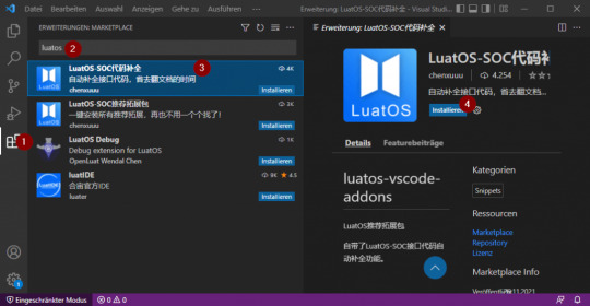
Installieren der Erweiterung "LuatOS" in Visual Studio Code Wenn dieses installiert wurde, dann muss noch die Datei "settings.json" für den aktuellen Workspace auf nachfolgenden Code angepasst werden. Diese erreichst du über "Datei" > "Einstellungen" > "Einstellungen" oder einfacher über die Tastenkombination "Strg + ,".
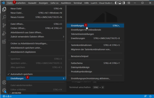
öffnen der Einstellungen in Visual Studio Code Wenn der Reiter "Einstellungen" geöffnet ist, findest du oben recht das Symbol "Einstellungen öffnen (JSON)" (siehe Bild).

Öffnen der Datei "settings.json" { "editor.fontFamily": "Consolas, 'Microsoft Yahei UI Light','Courier New', monospace", "editor.renderLineHighlight": "all", "editor.emptySelectionClipboard": false, "files.autoGuessEncoding": true, "editor.bracketPairColorization.enabled": true, "editor.guides.bracketPairs":"active", "luahelper.base.showOnline": false, }
Quellen
Für die nachfolgenden Kapitel habe ich mich aus diversen Quellen bedient, zum einen aus der offiziellen Dokumentation und auch aus dem russischen YouTube Video. Da ich aber weder russisch noch Chinesisch sprechen / lesen kann habe ich mich mit dem Google Translator und der Seite deepl.com bedient. Des Weiteren waren die Bilder auch schon recht aufschlussreich.
Flashen des Mikrocontrollers
Für den Upload des Codes benötigen wir ein zusätzliches Tool, welches unter https://cdndownload.openluat.com/Luat_tool_src/last_release/Luatools_v2.exe heruntergeladen werden kann. Mein Browser & Antivirus hatte zunächst die Verbindung abgelehnt, was ich manuell bestätigen musste. Wenn die EXE-Datei heruntergeladen und mit deinem doppelklick gestartet wurde, wird man mit einem Dialog darauf hingewiesen, dass Updates vorliegen. Diese installiere ich zunächst.
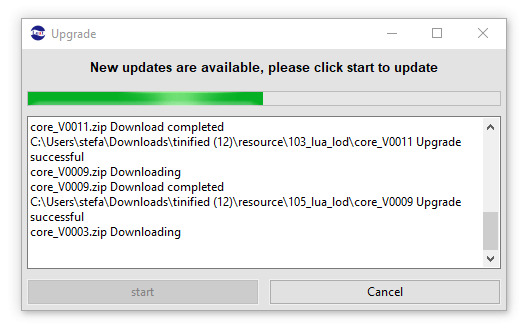
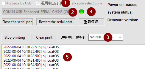
Installieren der Updates in Luatools Download des Flash-Files für den Damit wir mit dem Mikrocontroller kommunizieren können, müssen wir zunächst einige Einstellungen treffen. - zum einen muss die Checkbox (1) markiert werden, - der korrekte COM Port (2) muss gewählt werden, und - die Baudrate muss auf 921600 (3) eingestellt werden Wenn diese Einstellungen getroffen wurden, kann die Schaltfläche "Open Serial Port" betätigt werden und die kleine graue Lampe sollte sich grün verfärben (4). Im seriellen Output sollte man nun zeitgleich die Meldung " hi, LuatOS" finden.
Einstellungen für die Kommunikation mit dem ESP32-C3 aus luatools In meinem Fall verwende ich den Mikrocontroller ESP32-C3 und muss die Datei "luatoolsresourceesp32c3_lua_lodcore_V0003LuatOS-SoC_V0003_ESP32C3.soc" auswählen. Wenn die Datei ausgewählt wurde, kann die Schaltfläche "download" betätigt werden. Der Download dauert mit knapp 50 Sekunden recht lange und in der Zeit sollte der Mikrocontroller nicht abgesteckt werden!
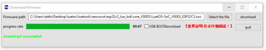
download der Firmware auf den ESP32-C3 mit luatools
Programmieren der Ausgabe "Hello World!"
Starten wir mit einem kleinen Programm und programmieren, dass die Ausgabe "Hello World!" auf der seriellen Schnittstelle ausgegeben wird.
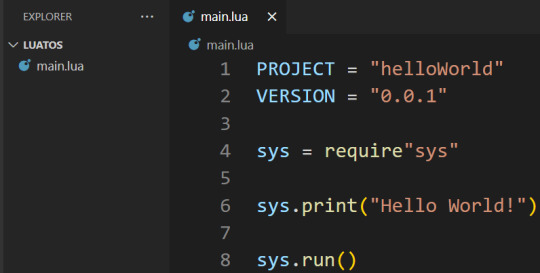
Programm "Hello World!" in Visual Studio Code In Visual Studio Code erstellen wir eine neue Datei "main.lua" und kopieren folgenden Code hinein. Die Datei muss den Dateinamen "main.lua" tragen denn sonst wird diese nicht hochgeladen! PROJECT = "helloWorld" VERSION = "0.0.1" sys = require"sys" print("Hello World!") sys.run() Diese Datei müssen wir jetzt mit dem zuvor wendeten luatool auf den Mikrocontroller hochladen.
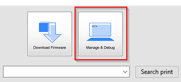
Im ersten Schritt klicken wir auf die Schaltfläche "Manage & Debug" oben rechts im Tool Luatools.
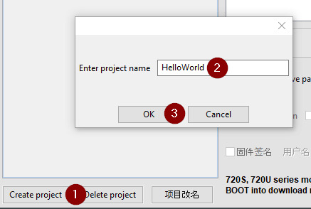
Im neuen Dialog erzeugen wir uns zunächst ein neues Projekt mit der Schaltfläche "Create project" (1), diesem müssen wir einen Namen vergeben (2) und dieses mit der Schaltfläche "OK" (3) bestätigen.
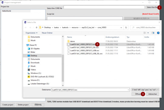
Wenn das Projekt erstellt wurde, dann wird die Schaltfläche "Select the file" (1) freigeben aus welcher wir die Firmware für den Mikrocontroller markieren (2) und diese über die Schaltfläche "Öffnen" (3) wählen.

Nun muss die zuvor erzeugte Datei "main.lua" gewählt werden, dazu klicken wir die Schaltfläche welche in der Grafik mit (1) markiert ist und navigieren in den Projektordner (2) und markieren die Datei (3) und betätigen dieses mit der Schaltfläche "Öffnen" (4).
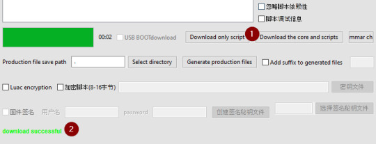
Im letzten Schritt betätigen wir die Schaltfläche "Download only script" (1), nach dem erfolgreichen Download wird die Zeile "download successful" in grün (2) angezeigt.

In meinem Fall musste ich einmal den Mikrocontroller über den Taster "RST" neu starten und die es wurde die Zeile "Hello World!" ausgegeben. Read the full article
0 notes
Text
A Peek at the Pico, Raspberry Pi's Newest Petite Powerhouse
Raspberry Pi Pico
8.80 / 10
Read Reviews
Read More Reviews
Read More Reviews
Read More Reviews
Read More Reviews
Read More Reviews

Shop Now
Meet the new Raspberry Pi Pico; a tiny microcontroller filled with big possibilities.
Specifications
Brand: Raspberry Pi
CPU: Dual-core 133Mhz ARM
Memory: 264Kb
Ports: microUSB
Pros
Powerful ARM Processor
Micro-USB Connectivity
Breadboard Mountable
Easy-To-Use Interface
Absolutely Adorable
Inexpensive
Cons
No Wi-Fi or Bluetooth connectivity
No Header Pins
I/O Port Labelling on One Side Only
No USB-C Connectivity
Buy This Product
Raspberry Pi Pico other
Shop
// Bottom var galleryThumbs1 = new Swiper('.gallery-thumbs-1', { spaceBetween: 10, slidesPerView: 10, freeMode: true, watchSlidesVisibility: true, watchSlidesProgress: true, centerInsufficientSlides: true, allowTouchMove: false, preventClicks: false, breakpoints: { 1024: { slidesPerView: 6, } }, }); // Top var galleryTop1 = new Swiper('.gallery-top-1', { spaceBetween: 10, allowTouchMove: false, loop: true, preventClicks: false, breakpoints: { 1024: { allowTouchMove: true, } }, navigation: { nextEl: '.swiper-button-next', prevEl: '.swiper-button-prev', }, thumbs: { swiper: galleryThumbs1 } });
We’ve managed to get our hands on the coveted Raspberry Pi Pico. Today, we’re going to be looking at some of the most important features and putting it toe-to-toe with some of the biggest names in small electronics.
We’ll be showing you what the Pico can do, and we’ll get you started with MicroPython, one of Pico’s supported programming languages. We’ll even offer up some code to try in case you decide to buy a Pico of your own.
What Is a Raspberry Pi Pico?
Raspberry Pi Pico is a new budget microcontroller designed by Raspberry Pi. It’s a tiny computer built around a single chip, with onboard memory, and programmable in/out ports. Historically, microcontrollers are used in a variety of devices from medical implants to power tools. If you have an electronic device sitting in your vicinity, there’s a good chance that there’s a microcontroller inside of it.
Key Features of the Pico
The Pico is built around the RP2040 microcontroller chip, which was designed by Raspberry Pi UK. It’s a Dual-Core ARM processor with a flexible clock that can run up to 133 MHz. The Pico also supports 1.8-5.5 DC input voltage, has a micro-USB input port, and an onboard temperature sensor.
Flanking the chip on all sides are a series of castellations that allow easy soldering to a Veroboard or breadboard. This dual in-line package (DIP) style form factor is stackable, and can also be used in carrier board applications.
Technical Specifications
21 mm x 51 mm
264kb on-chip RAM
2 MB on-board QSPI flash
2 UART
26 GPIO
2 SPI controllers
2 ISC controllers
16 PWM channels
Accelerated integer and floating-point libraries
3-pin ARM Serial Wire Debug (SWD) port
What’s So Special About the Pi Pico?
The Pi Pico is a different kind of microcontroller. It’s Raspberry Pi’s first, and it features ARM technology in its RP2040 silicon chip. Many technology companies are embracing silicon ARM chips, with major manufacturers like Apple leading the charge.
The punchy little Pico packs a staggering 26 multifunction general purpose input/output (GPIO) ports, including 3 that are analog. Alongside these ports are 8 programmable input/output (PIO) ports. Compare this to other microcontrollers like the Arduino Nano, and the Pico packs roughly 18% more GPIO capability.
The most considerable difference between the Pico and its competitors, however, is the $4 price tag. Low cost is the main selling point of this unique offering.
At launch, many online retailers sold out of the device due to the interest and Raspberry Pi’s favorable reputation. By setting the price so low, the Pico opens the door for a new class of high-powered, budget microcontrollers.
There are many potential applications for the new Pico. With its onboard temperature sensor, the device is an obvious choice for IoT projects.
One talented retro gaming enthusiast even used a Pico to build a gaming console with full VGA video support.
youtube
This means that makers who have been curious about Raspberry Pi, or microcontrollers in general, now have the ability to experiment for less than the price of a fancy cup of coffee.
Related: The Raspberry Pi Comes of Age With the Pi 400 Desktop
The Raspberry Pi Pico Processor
The RP2040 ARM chip is an interesting choice for the Pico. At 133MHz, the chip is capable of leaving more expensive boards, like the Arduino Uno, in the dust.
Using ARM processors seems to be an emerging trend in the world of microcontrollers. In addition to Raspberry Pi, both Sparkfun and Adafruit also offer boards with similar ARM technology.
The industry-wide switch was made for a single reason—speed. ARM processors give a considerable boost over standard Atmel chips. In a board this size, using an ARM processor is like dropping a fully kitted Porsche engine into a Volkswagen. On the other hand, many microcontrollers don’t require that much processing speed. Yet.
Ramping up performance means that makers who want to push the limits of the Pico will have an abundance of power to do so.
The I/O Ports
The GPIO ports on the Pi Pico feature several interesting functions for common uses such as operating a screen, running lighting, or incorporating servos/relays. Some functions of the GPIO are available on all ports, and some only work for specific uses. GPIO 25, for example, controls the Pico’s onboard LED, and GPIO 23 controls the onboard SMPS Power Save feature.
The Pico also has both VSYS (1.8V — 5.5V) and VBUS (5V when connected to USB) ports, which are designed to deliver current to the RP2040 and its GPIO. This means that powering the Pico can be done with or without the use of the onboard micro-USB.
A full list of the I/O ports is available on Raspberry Pi’s website in its complete Pico documentation.
Pico vs. Arduino vs. Others

One question on the minds of many makers is whether or not the Raspberry Pi Pico is better than Arduino?
That depends. Pound-for-pound, higher-end Arduino boards like the Portenta H7 make the Pico look like a toy. However, the steep cost for a board of that caliber might be a tough pill for the microcontroller hobbyist to swallow. That's why the smaller price tag on the Pico makes it a win for makers who enjoy low-risk experimentation.
Along with minimal cost, the Raspberry Pi jams an extensive feature set into the Pico, comparable to boards like the Teensy LC, and the ESP32. But neither of these competitors manage to challenge the budget-friendly Pico on price.
That's what makes the Pico such a fantastic value, and a great choice for hobbyists and power users alike.
The Pi Pico: What’s Not To Love?
Unfortunately, to drive the price of the Pico down, Raspberry Pi had to make a few compromises. The most notable of which is the lack of an onboard radio module. Neither Bluetooth nor Wi-Fi is supported without add-ons.
The Wi-Fi limitation can be eliminated by adding a module like the ESP-01. Bluetooth support may prove a bit more challenging. If you need an all-in-one solution for your products, you’re better off skipping the Pico, and spending a little extra for something like the Pi Zero W, or ESP32.
Additionally, many early adopters are complaining about the lack of GPIO labeling on the top of the board. Raspberry Pi provides an extensive amount of documentation on its website to address this, but pointing-and-clicking, or thumbing through paperwork when you have a hot soldering iron in your hands isn’t often desirable.
Lastly, the lack of I/O pin headers is something of an issue for some, as it means less convenience when swapping I/O components. This minor annoyance can be solved via the use of leads, soldering the component wiring directly to the Pico, or using a breadboard.
If you’ve been using microcontrollers or small electronics for any period of time, then an unpopulated board is most likely a non-issue. Of course, you could also add your own pin headers if you plan on regular experimentation with different external components.
The final rub with the Pico is the micro-USB port. With many other microcontrollers like the Portenta H7 moving toward USB-C, Raspberry Pi's micro-USB port seems dated.
Logically however, the decision to use micro-USB makes sense. It was done by Raspberry Pi to keep costs as low as possible, and to keep interface capability almost universal. Everyone we know has at least a few micro-USB cables tucked away somewhere in their homes.
However, with future versions, a USB-C interface would be a nice addition to an already spectacular package.
Related: A Beginners Guide To Breadboarding With Raspberry Pi
Programming the Raspberry Pi Pico
Interfacing with the Pi Pico can be done via C/C++, or via MicroPython in the Read-Eval-Print-Loop or REPL (pronounced “Reh-pul”). The REPL is essentially a command line interface that runs line-by-line code in a loop.
In order to access the REPL, you’ll need to install MicroPython onto the Pico. This process is simple and only involves four steps.
Installing MicroPython
Download MicroPython for Raspberry Pi Pico from the Raspberry Pi Website
Connect the Pico to your computer via micro-USB while holding the BOOTSEL button
Wait for the Pico to appear as an external drive
Copy the MicroPython file to the Pi Pico, and it will automatically reboot
You can access the REPL in a number of ways. We used the screen command in a macOS terminal window to access the serial bus connected to the Pico. To accomplish this with Terminal, you’ll first open a new terminal window, then type ls /dev/tty*

From there, find the port where the Pico is connected. It should be labeled something like /dev/tty.usbmodem0000000000001. Then run the command:
screen /dev/tty.usbmodem0000000000001
Your cursor should change. Hit Return and the cursor will change again to >>>.
In the image below we've included the classic Hello World (Hello, Pico) command-line program in the REPL, along with a few lines of code that will turn the Pico's LED on and off. Feel free to try them yourself.

For more information, we recommend you invest in the official starter guide to MicroPython that Raspberry Pi has published on their website.
Download: MicroPython for Raspberry Pi Pico (free)
Using the Raspberry Pi Pico With Thonny

If you’re looking for a more proper coding environment, the Raspberry Pi Pico will also allow access to the REPL with Thonny. To enable this feature, first download and install Thonny. Once installed, connect your Pi Pico. Open Thonny and you'll see information indicating your Pico is connected in the Shell.
At the bottom right of the screen, you should see a version of Python. Click this version and select MicroPython (Raspberry Pi Pico) from the drop-down menu.
Now you can type commands into the Shell, or you can use Thonny’s editor to write or import multiple lines of code.
The abundance of interface possibilities make the Raspberry Pi Pico easy to program. For those who are familiar with MicroPython, this should be nothing new. For beginners, however, Thonny provides a powerful interface and debugger to get started with programming.
Download: Thonny (Free) Windows | Mac
Should I Buy the Raspberry Pi Pico?
The Raspberry Pi Pico is a powerful budget board that is perfect for hobbyists, or makers just starting out with microcontrollers. The documentation, low cost, and wide range of possibilities for the Pico also make it a great choice for seasoned small electronics wizards. If you’re a DIYer who loves to tinker, or you just want to challenge yourself to a weekend project, then you’ll love playing with the Pico.
On the other hand, if you don't have one or more projects in mind that need a microcontroller, then this board is probably not for you. Also, if your project needs Wi-Fi connectivity or Bluetooth, then the Pico won’t scratch that itch. And finally, for users who aren’t comfortable learning MicroPython, or exploring C/C++, the Pico isn't ideal. And remember: this Raspberry Pi is not like the others. It will not run a full Linux operating system.
But, if you dream in Python, or if you love the smell of solder, then you won't regret grabbing this tiny powerhouse. Most of all, if the sight of the sports-car-sleek RP2040 gets your creative gears turning, then we think you’ll really benefit from picking up the Pico.
Serving up Several Sweet Possibilities
While it isn’t perfect, the Raspberry Pi Pico is a strong entry into the world of microcontrollers. The reputation that Raspberry Pi has built for quality electronic components at a relatively low price extends to the Pico.
It’s everything a Raspberry Pi should be: small, sweet, and superb. It’s beautifully designed, and extremely inexpensive. But the best part isn’t the looks or the low cost.
The best part about this small wonder is picking it up, and holding it in your hands. It's feeling the tug of electronic inspiration. It's realizing just how powerful the Pico is, and what it means for microcontrollers going forward.
And truthfully, we think it's amazing that something as small as the Pico can offer so many unique possibilities.
A Peek at the Pico, Raspberry Pi's Newest Petite Powerhouse published first on http://droneseco.tumblr.com/
0 notes