#esp8266 flash download tool
Explore tagged Tumblr posts
Visit Tumblr Blog
Explore Tumblr blogs with no restrictions, modern design and the best experience.
Last Seen Tumblr Blogs


Fun Fact
Tumblr was acquired by Yahoo for $1.1B in 2013.
Text
Flash Download Tool como Gravar Binários no ESP32
Este post é um tutorial de como gravar binários no ESP32 usando a Flash Download Tool disponibilizado pela Espressif.
Flash Download Tool é uma ferramenta disponibilizado pela Espressif para exportar arquivos binários para o ESP32. Baixar e instalar Flash Download Tool Antes de tudo é necessário baixar o programa Flash Download Tool no site de Espressif, após baixar, abra e defina chipType como ESP32. Além disso, haverá outras configurações mas não serão necessárias, por ultimo click ‘ok‘. Entendendo o Flash…
Ver no WordPress
#download flash tool exe#esp 32#esp32 arduino#esp32 arduino ide#esp32 board#esp32 bootloader#esp32 flash download tool command line#esp32 wroom#esp8266 flash download tool#espressif esp32 flash download tool#flash download tool esp32#flash download tool for esp32#flash download tools#flash download tools (esp8266 e esp32 & esp32-s2)#usb flash download tool
0 notes
Text
[Media] DSTIKE Deauther Watch
DSTIKE Deauther Watch Deauther Watch is still an ESP8266 development board, but you can wear it like a smartwatch. It comes installed with the latest ESP8266 Deauther software. With this software, you can perform different attacks to test WiFi networks. Please note that the ESP8266 does only support 2.4GHz. You can also use it to develop your own software. It is simple to use, just like any other ESP8266 development board. FAQ \ WiKi \ Software: https://github.com/SpacehuhnTech/esp8266_deauther Firmware Burning tool: https://github.com/nodemcu/nodemcu-flasher Hardware: https://github.com/lspoplove/Deauther-Project Video tutorial: https://www.youtube.com/watch?v=TMvpJiE8Yy8 Quick product upgrade tutorial: 1. Download CP2102 driver 2. Download the firmware 3. Download nodemcu-flasher 4. Click the gear to select the corresponding binfile. The programming mode selects DOUT. The rate selects 961200. Click Flash start and wait for the progress bar to reach the end and then power on. Buy online: 🛒 https://ali.ski/0n0Cab #dstike #watch #esp8266

10 notes
·
View notes
Text
How to Program NodeMCU ESP8266?
Requirements
An ESP8266 module.
Arduino UNO, UARTbee or any UART to the USB device.
Jumper wires.
Arduino IDE version 1.6.6 or higher.
Get Started
First, we’ll need to identify the pinout of ESP8266.

To set the ESP8266 in programming mode you need to connect its wires like this:

NOTE: If you are using an Arduino UNO you will need to set Arduino RST to GND. Please be careful with the VCC of the ESP8266, it works only with a 3.3V supply.
Setup the Arduino IDE
1. Download Arduino IDE.
2. Open your IDE and click on File -> Preferences".
3. In “Aditional Boards Manager URLs” add this line and click on “OK”:
http://arduino.esp8266.com/stable/package_esp8266com_index.json
4. Go to “Tools -> Board -> Boards Manager”, type “ESP8266” and install it.
5. Go again to “Tools -> Board” and select “Generic ESP8266 Module”.
Flash your code
Now you’re ready to use your ESP8266 as a stand-alone module without needing an external micro-controller.
ESP8266 NodeMCU Basics: Datasheet, Pinout, etc.>>
#esp8266#nodemcu#wifi module#program#arduino#tutorial#microcontroller#ic#ic world#ic chips#electronic#technology#technolovers#technolife
0 notes
Text
Home Automation with Raspberry Pi and OpenHab
his week we've got something special for you this is the first video in a series that we're putting together show you how to build your own home automation system using the open source software open tab we'll be building a Raspberry Pi touchscreen command center they can interface with over a hundred and fifty different smart home products and provides an interface for control and task scheduling instead of using an existing product though we'll build our own wirelessly controlled RGB LED strip that interfaces with openhab that allows you to control it from any smartphone or computer on your network openhab is great because it interfaces with so many products it's free it's open source and it's incredibly versatile it also runs on Windows OSX and Linux so you don't necessarily have to use a Raspberry Pi for this project if you have an old laptop or desktop kicking around you can just as easily run the same set up we also want to thank Aero for sponsoring this build they've given us access to their vast inventory of electronic components in order to make this project series possible we're really excited to share what we've come up with main parts for this build are a Raspberry Pi and touchscreen as well as the components used to control the neopixel strip you can purchase the component from Aero or other online electronics vendors you also need a few tools for soldering and programming microcontroller begin by assembling the Raspberry Pi touchscreen and mounting it to the PI then download the latest build of raspbian from the Raspberry Pi website and flash it onto an SD card plug in a keyboard and Wi-Fi adapter then insert the card into the pi and boot it up go through the configuration process for your setup in order to get the touchscreen to work you'll likely need to run a few commands in the command line to update raspbian after the update restarting the PI will flip the screen upside down if that's a bother to you you can flip it back by adding the line LCD underscore rotate equals 2 to the config dot text file in the boot folder now it's time to install our home automation control software openhab and the associated openhab add-ons we'll be using this gets a little command-line heavy so for a full list of commands click on the link to the project instructions in the description below since the communication between our openhab server and our lights will occur over a messaging protocol called MQTT we'll need to install mosquito and MQTT broker finally download our pre-made openhab configuration files in stall them in the Associated openhab folders with openhab setup on a Raspberry Pi it's time to switch to building our neopixel strip controller the cheap Wi-Fi enabled at Adafruit esp8266 huzzah board is perfect for this but because it uses 3.3 volt logic level instead of the neopixel strips five volts will need to solder a logic level converter between them before we start that though solder the provided header pins to the board so we can program it using an FTDI adapter now on the low-level side of the converter pin to from the ESP will connect to a 1 pin 3 2 LV and ground to ground on the high side of converter pen b1 is soldered to the neopixel data pin wire that's the striped wire on the neopixel connector and ground will go to ground solder a red wire to the HV pin on the converter and another red wire to the B+ on the ESP male end of the neopixel strip will also provide power for the ESB so solder the red wire from the strip to the red wires coming from the V Plus and HV pins and the black wire goes to the ground on the ESP after that plug the neopixel strip into the wall with a provided cord and make sure that the ESP is getting power by hitting the reset button to see if the on-board LED flashes with everything wired up it's time to flash the ESP using the arduino ide take a moment to install the boards and libraries by following the links in the description and then open the provided arduino sketch then edit the sketch to include your Wi-Fi network settings and the PI's IP address you can check your PI's IP address by typing IP space addr space show into the command line connect your computer to the ESP with an FTDI cable and set your board and port in the arduino ide put the ESP into programming mode by holding the GPIO 0 button down and pressing the reset button then upload your code after it's flashed open a serial monitor and make sure that the board connects to your Wi-Fi network successfully with openhab configured in our neopixel strip on the network it's time to test it out download the openhab app to your phone or tablet it's available for both Android and iOS then open it and select settings in the upper right corner change the open have URL field to your PI's IP address followed by a colon and 8080 exit the menu and your phone should connect to openhab bringing up your led controller alternatively you can also control the LEDs from any computer on the same network including the pi by entering the PI's IP address followed by slash openhab app question mark sitemap equals home I know a lot of you probably thinking that there are a lot easier ways to control RGB LED strips wirelessly but there's a reason we decided to do it this way openhab is extremely versatile and we've only just scratched the surface of the things you can do with it you can control things with voice commands monitor sensor networks even set up rules for automating devices from email or if t8 events in future videos we'll show you how to build other cool devices that connect to openhab make your house even smarter that's it for this time we'll see you in the next weekend project if you liked this video subscribe to our channel or send us a comment on Facebook or Twitter be sure to check out our other project videos or visit us on make zine calm
https://youtu.be/G65aCy_SsYI
0 notes
Text
Getting the ESP8266 Code Ready for C
Espressif chips are the sexy mcu’s these days. If you’re reading this, it’s more likely because you’re already familiar with their with what they’ve got to offer. They made their first splash - and I mean like the bombest cannonball you’ve ever seen - with the esp8266 which explorers spent some good time opening the SDK and even going so far as decapping and tracing the silicon. The chip came as an oddly shaped module with 8 pins (the ESP8266-01) then exploded into a bunch of others.

I’m here to convince you to get one if you haven’t and experiment with me because there’s a world of possibility with these. If qualitative statements don’t do it for ya, then check out these specs mostly from its wikipedia entry:
32-bit CPU (Tensilica Xtensa L106 operating at 80MHz
64KiB of instruction RAM and 96KiB of data RAM
802.11 b/g/n wifi with WPA/WPA2, WEP, and open security
2 GPIOs exposed to us (their MUXed functions aren’t great-GPIO 0 is muxed to SPI chip select and GPIO 2 is muxed to I2C SDA... ^^; buuut...)
Each GPIO can be configured for pull-up, can trigger interrupts, be configured as open drain or push-pull. Reportedly (from the datasheet), we can also do PWM but it says in another breath that it is “software programmable” which I take to mean DIY.
500kB or 1MB external SPI flash on the module (not on the SoC)
Afraid you’re going to be spending too much to get all that? YOU CAN GET 4 FOR $14.00 SO NO EXCUSES!
Of course not all of the pins are exposed so that stinks and means we don’t get all of the functionality but we’ll see what we can do with what we’ve got and maybe I’ll do another blog entry if that’s what we’d like to do.
Anyway, I love these and think you should too. I wanted to share how to get as close to main() as possible, and how to make your own tiny programming jig so....let’s GO!
Hardware
Can’t start the software without a little hardware! We need to make a quick programming jig to move between “serial programming” and “run” mode.
I used parts-box parts but you can get similar parts from almost anywhere. Just in case, here’s an ingredients list:
3.3v FTDI cable/module
ESP8266-01
Push button switch (for the reset line which is active low. You’ll see I used a mouse button for some reason but if you use a push button, you’ll need a pull up resistor)
A latched push button (for power but I used another mouse button)
DPST/DPDT switch
Headers (both female and male)
Some perf board
Here are the pin configs for serial programming:

and so this is the schematic we’re after:

Again, I only had the parts I had so here’s the schematic with what I had:

And here’s a quick map of how the perfboard is laid out:

(The boxes and blue lines represent top-layer components and wires, the red lines represent solder mazes)

(Here’s the back side so you can basically put the parts in as in the first photo and solder the traces on the back like this photo)
When all is said and done, you end up with this:

Easy as pie and hardware part done!
Software
Alright, so next up let’s get the toolchain setup, upload the blinky code, modify, and upload again so we feel good and ready to move onto projects. I chose open-esp-sdk purely because others really liked it.
This process is pretty typical but here’s the idea:
Install Dependencies (apt-get) -> Clone the Repository (git) -> Build the Project (make) -> Globalize the Tools (assigning to a global)
Then it’s time to build the example and load it up on the ESP.
Build Blinky (make) -> Power Cycle the device in program mode -> Load the new binary to the board (esptool.py) -> drink beer in celebration
Setting up the Environment
Install the Dependencies - download and install all the programs that will help you build the environment, build the esp binaries and use the upload tools
sudo apt-get install make unrar-free autoconf automake libtool gcc g++ gperf flex \ bison texinfo gawk ncurses-dev libexpat-dev python-dev python python-serial \ sed git unzip bash help2man wget bzip2 libtool-bin
Clone the repository - for those who are new to git (many at my company were when they came aboard, obviously me included) all this is is just copying a project that someone has posted to git down to your computer. Make sure you go to the directory where you want your project to reside and type:
`git clone --recursive https://github.com/pfalcon/esp-open-sdk.git`
Build the Environment - When it’s done, cd into the esp-open-sdk directory and make the project
cd esp-open-sdkmake STANDALONE=y
The “STANDALONE=y” ensures you get the xtensa toolchain and the esp SDK.
Depending on your hardware this may take a while. Just for shits and giggles I installed it on my Crubuntu laptop which took an hour (to be fair I was watching netflix on the Chrome side). If it goes off without a hitch, it will report
Espressif ESP8266 SDK is installed, its libraries and headers are merged with the toolchain
Pitfalls
I’ve encountered two errors when I tried this though - one was when I followed the github instructions and didn’t try to install libtools-bin (since it said you may not require it). For safety, I just put it in my apt-get command above.
The other was because I had played around a bunch on my computer and had the LD_LIBRARY_PATH variable set to which it complained
[ERROR] Don't set LD_LIBRARY_PATH. It screws up the build.
If that happens, make sure you clear your LD_LIBRARY_PATH environmental variable with
unset LD_LIBRARY_PATH
and try again.
Globalize the Tools - We’ll want to make it so that we can access the xtensa gcc toolchain (which we’ll use to compile link and convert our sourcecode to ELF) and the esptools (which we’ll use to convert to a binary and write to flash locations on the chip over serial) everywhere. To make that happen, we need to add the path to xtensa-lx106-elf-gcc and esptool.py to the ~/.bashrc - the file that loads every time we load a terminal session.
There should have been a line above the success message that says Xtensa toolchain is built, to use it:
export PATH=[your_path_to_esp_open_sdk]/esp-open-sdk/xtensa-lx106-elf/bin:$PATH
Go ahead and do that - type:
export PATH=[your_path_to_esp_open_sdk]/esp-open-sdk/ xtensa-lx106-elf/bin:$PATH
But let’s also add it to our ~/.bashrc which controls what happens when we open a new terminal:
echo “export PATH=[your_path_to_esp_open_sdk]/esp-open-sdk/ xtensa-lx106-elf/bin:$PATH” >> ~/.bashrc
and then we’re good! To test if that worked, cd to the esp-open-sdk directory and then do
cd examples/blinky
and type
make
If that went through well (i.e. it didn’t throw any complaints to you), you’ve properly configured your environmental path variable. Now remove the blinky binaries (make seems to make different binary locations than those used in make flash and make clean)
rm -f blinky blinky.o blinky-0x00000.bin blinky-0x10000.bin
Testing with blinky.c
Our next goal is to run blinky on the board.
Test the Serial Port
First let’s make sure we have access to the serial port so we can program the device. Connect your FTDI programmer to your USB port and type
dmesg | grep FTDI
It should list a line like this to tell you which /dev the FTDI connected to like
usb 1-2: FTDI USB Serial Device converter now attached to ttyUSB0
Next, send something like (where ttyUSB0 is the device you got)
echo -ne “\r\n” > /dev/ttyUSB0
If you just get another prompt pop up immediately after, you shouldn’t have anything to worry about and can move to the next section. If you get the Permission Denied message, you need to add yourself to the same group as your FTDI port. Let’s find out which group we need to be a part of. Type:
ls -l /dev/ttyUSB0
and you should get something like:
crw-rw---- 1 root serial 188, 0 Jun 19 02:52 /dev/ttyUSB0
Many sites online just say to add to “dialout” but you see that my port is connected to the group “serial.” I can add myself to that group with:
sudo usermod -a -G serial alexmo
and then log out and log back in.
Now when you’re back in, if you retype
echo -ne “\r\n” > /dev/ttyUSB0
you shouldn’t see the permission denied message.
Build
Build with
make
You’ll see a few new files. The binaries marked blinky-0x00000.bin and blinky-0x10000.bin tell you where they should be written.
Program
Now let’s program the device with the binaries. If you see blinky-0x00000.bin and blinky-0x10000.bin, just type
esptool.py write_flash 0 blinky-0x00000.bin 0x10000 blinky-0x10000.bin
It will work on it:
esptool.py v1.2 Connecting... Auto-detected Flash size: 4m Running Cesanta flasher stub... Flash params set to 0x0000 Writing 36864 @ 0x0... 36864 (100 %) Wrote 36864 bytes at 0x0 in 3.2 seconds (91.5 kbit/s)... Writing 196608 @ 0x10000... 196608 (100 %) Wrote 196608 bytes at 0x10000 in 17.1 seconds (92.1 kbit/s)... Leaving...
and then start blinking!

0 notes
Photo


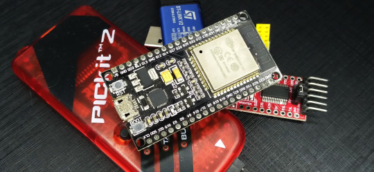
Meet the Microbit a Hacker’s dream come to life
The micro:bit is a small ARM microcontroller developed by the BBC, along with a gaggle of technology giants, to give away to children in the United Kingdom to help them learning computing. The device was released to teachers in early 2016.
As a hardware hacker, I was curious about how this board compared to an Arduino or Raspberry Pi. As always, I also wanted to see how the micro:bit might play with a Linux notebook and if it had a place in the Off-The-Shelf hacker’s tool box.
The device is interesting and has some cool features. Let’s take a look.
Hardware Overview
The board fields a 16 MHz, 32-bit Arm Cortex-MO micro-controller, 256 KB of flash and 16 KB of static RAM. It also has a Bluetooth Low Energy radio onboard for local networking with a super phone or other Bluetooth-equipped device. There’s an additional ARM microcontroller that handles the USB connection and external power management. As an Inter-Integrated Circuit (I2C), it includes an NXP/Freescale MMA8652 three-axis accelerometer and a NXP/Freescale MAG3110 three-axis magnetometer. The front-end user interface is a 25 surface-mounted LED array (arranged in a 5 X 5 matrix) and two push buttons. The back side of the board has the micro-USB connector, a power/upload status LED, a reset button and an external 3.0-volt connector.
There’s also a 23-pin edge connector and 5-ring connectors. You can connect alligator clips or banana plugs to the ring connectors for simple projects.
The two right ring connectors are for +3.0 volts and ground. Pins 0, 1 and 2 serve as analog inputs, while the remaining 23 connectors function as GPIO, analog in, power, and ground pins. Some of the pins are shared with the onboard LEDS. Various pins also support I2C and SPI buses.
There’s a convenient help page describing the pins in much greater detail.

How about Software?
Recall that the Raspberry Pi is a multi-user, multi-tasking system. In contrast, the micro:bit is similar to the Arduino microcontroller. It’s doesn’t have a Linux operating system or micro-SD card. There isn’t a WiFi stack, either. Don’t let that put you off, it’s a nice little package with plenty of power and capabilities. Code development is handled on a notebook and uploaded to the micro:bit as firmware.
The micro:bit uses web-based applications for editing and uploading code. Of course, using web-based tools means you’ll need a WiFi or Ethernet connection on your Linux notebook.
Don’t have WiFi? No problemo, use your super-phone. Download the Android app and pair the micro:bit with your phone over Bluetooth. The web-based applications work via the phone, as well. In an upcoming article, we might cover using the Android app with the micro:bit.
Several of the editors are visual-based, “slide the parts together” apps quite suitable and intuitive for children and beginners. They include:
MicroSoft PXT: Supports block-based editing and JavaScript.
Block Editor: Supports drag-and-drop code blocks.
Javascript: Code Kingdom is a drag-and-drop editor for JavaScript.
I prefer traditional text editors, so fortunately, there are a couple of those, as well:
Python: Text-based editor that has a collection of pre-built code snippets for use in your projects
Microsoft Touch Develop: An editor that’s designed for building mobile applications with a touchscreen
I’m somewhat familiar with Python, so that’s the one I used during this review. Here’s a screenshot of the requisite “Hello, World” script, with some additional code I snarfed from the reference manual.
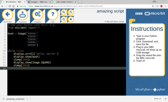
The MicroPython documentation is easy to use, comprehensive and full of useful code snippets. Start with the tutorial introduction page. There’s a handy index along the left side of the screen, that will take you to the various topics.
Once the code was finished, I simply clicked the “Download” button to compile everything into a .HEX file. The file then showed up in my /home/rob/Downloadsdirectory. I used the provided USB cable to connect the micro:bit board to my Linux notebook and copied the file into the /media/rob/MICROBIT directory. Using the Thunar file manager application on Linux makes handling files a breeze.
After copying the file (uploading) to the MICROBIT directory, the board will reboot and run the script. If there is an error, a message will scroll across the LED array, pointing to the offending line in the code.
Slick!
Going Further
Even if you are used to working in the Arduino IDE ecosystem, I think the micro:bit shows a lot of promise as an easy-to-program micro-controller platform. Python is gaining in popularity on nano-sized systems. You may have already used Python with the Raspberry Pi.
And, I like the idea that you can simply compile the program and use a simple file copy to upload the firmware to the board. That’s a heck of a lot easier than the standard Arduino upload, particularly to ESP8266 boards.
While we didn’t get into general purpose input/output (GPIO) capabilities today, the micro:bit is a solid product and I’ll likely cover other details and features, in future articles.
This product is not available in the US and is currently sold in the UK and when more information is available on how you can get you hands on one our blog will be updated. “Stay tune”
Read More Cyber New’s Visit Our Facebook Page Click the Link : https://www.facebook.com/pages/Cyber-crew/780504721973461
Read More Cyber New’sVisit Our Twitter Page Click the Link : https://twitter.com/Cyber0Crew
~R@@T @CCE$$~
0 notes