#esp32 board
Explore tagged Tumblr posts
Visit Tumblr Blog
Explore Tumblr blogs with no restrictions, modern design and the best experience.
Last Seen Tumblr Blogs


Fun Fact
Average visit duration of Tumblr.com is 10 mins and 25 secs.
Text
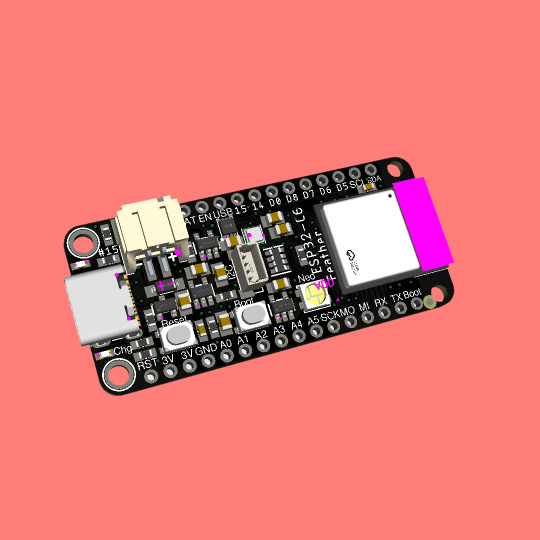
Coming soon - This ESP32-C6 feather is a Matter of fact
ESP32-C6 (https://www.adafruit.com/product/5672) is Espressif’s first Wi-Fi 6 SoC integrating 2.4 GHz Wi-Fi 6, Bluetooth 5 (LE) and the 802.15.4 protocol. It brings the goodness you know from the low-cost C3 series (https://www.adafruit.com/product/5337) and improves it with Zigbee/802.15.4 at 2.4Ghz. That means it could make for great Matter (https://csa-iot.org/all-solutions/matter/) development hardware!
We took our Feather ESP32-S2 (https://www.adafruit.com/product/5000) and swapped out the 'S2 for a C6. Plus some re-routing and here's what we've got: a C6 Feather with lots of GPIO, lipoly charging and monitoring with the MAX17048, (https://www.adafruit.com/product/5580) NeoPixel, I2C Stemma QT port, and a second low-quiescent LDO for disabling the I2C and NeoPixel when we want ultra-low power usage. We also tossed a BME280 (https://www.adafruit.com/product/2652) on there, so you could use it immediately as a low power temp/hum/pressure sensor.
#esp32-c6#wifi-6#bluetooth-5#zigbee#matter-protocol#feather-board#gpio#lipoly-charging#i2c-stemma-qt#bme280-sensor
4 notes
·
View notes
Text
STM32 e módulo LoRaWAN da Radioenge
Aprenda como eu fiz uma integração do módulo LoRaWAN da Radioenge e STM32 através da STM32CubeIDE
O STM32 e módulo LoRaWAN da Radioenge são uma bela junção para aplicações de baixo consumo de energia e longo alcance, tanto é que o próprio módulo tem um STM32L presente. Este projeto foi inteiramente construído dentro da STM32CubeIDE como uma forma de estudo e exemplo, então seu funcionamento é um pouco diferente do funcionamento no Arduino IDE. De qualquer forma a infraestrutura está o mais…
View On WordPress
#arduino lorawan#arduino lorawan library#helium lorawan#lorawan#lorawan alliance#lorawan arduino#lorawan board#lorawan class a#lorawan communicator#lorawan devices#lorawan diagram#lorawan esp32#lorawan gateway#lorawan network#lorawan stm32
0 notes
Text

Arduino IDE Boards Manager - Do NOT Install ESP32 by Espressif Systems Version 3.00-alpha1
As usual, I opened the Arduino IDE on my Windows-11 machine, and as a first action, I allowed the recommended updates. Not suspecting any significant problems, I added some code and compiled it, only to end up with multiple error messages. I found nothing wrong with the code I had added, and the error messages didn't make sense. They mainly pointed to the code for the internal CAN controller and ESP timer programming.
1 note
·
View note
Text
You can just barely see it but the new @rickybabyboy circuit works (indicated by the led lighting up). This version of the circuit will let him interact with the conductive cloth of the circuit a couple feet away. Later I plan on hooking this up to the GPIO of one of the esp32 boards I have and setting up a pillow for Ricky to jump on and test this with
87 notes
·
View notes
Text

Another 2022-present portable computer thing. This is a 1991 Corvallis Microtechnologies PC5-L. It's a ruggedized, waterproof handheld MS-DOS computer meant for industrial applications. It ran on Ni-Cd batteries and they died so now it runs on AA's I got two of them for $50 on eBay during one of those months when i impulse buy obscure electronics as a form of escapism This thing is an absolute brick. You could murder someone by hitting them on the head with this, and it would work fine afterwards. Here's pictures of its organs for anyone curious:


That thick red wire around the screen PCB is a heater. Yep there's a setting to heat up the LCD so it doesn't get sluggish or shatter when you decide to leave it in the freezer. The thing runs on a little system-on-chip thing, which is interesting to see coming from the early 90's. Iirc the datasheet says it's capable of analog video out as well as driving the LCD, but I haven't poked around enough to enable it. Might be cool to hook it up to a TV. I did, however, open those 512k storage modules and I saw some unpopulated footprints on the boards. So I ordered some of the same chips, and at some point I'mma try soldering them on and see if it recognizes the extra space. They came with two voltmeter modules, which I couldn't get to work, so I took one of the casings and made it into a USB and WiFi adapter using an ESP32 running Zimodem, since this thing has RS232 ports on the top. I also made my own charging adapter, since they didn't come with one. I see that internal PCMCIA slot, and I tried putting a CF card adapter in, and tried installing the drivers, but it didn't work. I'm not good at DOS tbh, and I know nothing of what this slot is for. I might come back to it later. I did all of this in 2022-23 and haven't messed with it since. Except to use it to talk to my Kaypro 4 '84:

More on that one later. I love portable computers !!!!!
101 notes
·
View notes
Text
So I was prototyping and scoping things out, and it turns out there's actually a fair bit of room in the core of a ghost for electronics

From front to back, we have:
The front casing - please ignore how scruffy this looks, it was a rough print with whatever material I had lying around

The led ring - not entirely sold on this bit. Might see if I can find a small round screen to fit inside, once I've modified the design a bit

The seeed xiao esp32-c3 core. Might see if I can upgrade this to their S3 or C6 version for the proper build

A nifty lil' qt py bff board that incorporates both a BMP280(for environmental sensing) and a BMO055 for orientation/speed/heading/etc.

Another bff board, this time with a teeny-tiny lil' audio amplifier & sd card reader - so I can have it make a great many sounds

And finally the rear case

Oh god... I'm definitely going to have to get back into destiny now, aren't I?
12 notes
·
View notes
Text
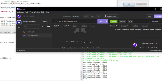
It works!*
So I (FINALLY) put the final touches on the software for my robot PROTO! (Listen, I am a software person, not a coming-up-with-names person)
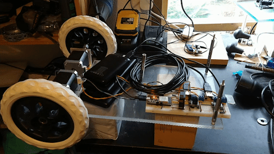
Basically, it is a ESP32 running him. He takes HTTP messages. Either GET odometry, or PUT twist. Both just being a string containing comma separated numbers
Odometry is the robots best guess based on internal sensors where it is (Since PROTO uses stepper motors, which rotates in tiny tiny steps... it is basically counting the steps each motor takes)
Twist is speed, both in x,y and z directions, and speed in angular directions (pitch, roll and yaw). This is used to tell the robot how to move
Now, since PROTO is a robot on two wheels, with a third free-running ball ahead of him, he cannot slide to the side, or go straight up in the air. You can TRY telling him to do that, but he will not understand what you mean. Same with angular movement. PROTO can turn left or right, but he have no clue what you mean if you tell him to bend forward, or roll over.
The software is layered (Which I use a BDD diagram to plan. I love diagrams!)
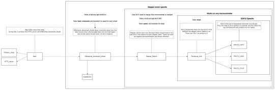
Basically PROTO gets a twist command and hands that over to the Differential_Movement_Model layer.
The Differential_Movement_Model layer translate that to linear momentum (how much to move forward and backwards) and angular momentum (how much to turn left or right). combines them, and orders each wheel to move so and so fast via the Stepper_Motors layer.
The Stepper_Motors turns the wanted speed, into how many steps each stepper motor will have to do per second, and makes sure that the wanted speed can be achieved by the motors. It also makes sure that the wheels turn the right way, no matter how they are mounted (In PROTO's case, if both wheels turn clockwise, the right wheel is going forward, and the left backwards.). It then sends this steps per second request down to the Peripheral_Hub layer.
The Peripheral_Hub layer is just a hub... as the name implies, it calls the needed driver functions to turn off/on pins, have timers count steps and run a PWM (Pulse-width modulation. It sends pulses of a particular size at a specific frequency) signal to the driver boards.
Layering it, also means it is a lot easer to test a layer. Basically, if I want to test, I change 1 variable in the build files and a mock layer is build underneath whatever layer I want to test.
So if I want to test the Stepper_Motors layer, I have a mock Peripheral_Hub layer, so if there are errors in the Peripheral_Hub layer, these do not show up when I am testing the stepper motor layer.
The HTTP server part is basically a standard ESP32 example server, where I have removed all the HTTP call handlers, and made my own 2 instead. Done done.
So since the software works... of course I am immediately having hardware problems. The stepper motors are not NEARLY as strong as they need to be... have to figure something out... maybe they are not getting the power they need... or I need smaller wheels... or I will have to buy a gearbox to make them slower but stronger... in which case I should proberbly also fix the freaking cannot-change-the-micro-stepping problem with the driver boards, since otherwise PROTO will go from a max speed of 0.3 meters per second, to most likely 0.06 meters per second which... is... a bit slow...
But software works! And PROTO can happily move his wheels and pretend he is driving somewhere when on his maintenance stand (Yes. it LOOKS like 2 empty cardboard boxes, but I am telling you it is a maintenance stand... since it sounds a lot better :p )
I have gone over everything really quickly in this post... if someone wants me to cover a part of PROTO, just comment which one, and I will most likely do it (I have lost all sense of which parts of this project is interesting to people who are not doing the project)
129 notes
·
View notes
Text
met with the interim therapist yesterday
she now agrees that i have made a good faith effort with the new p.a. and that it is reasonable to try to find someone else
she also put our work on hold indefinitely
next week i need to do something but i am not sure what or how
--
[not sure if this should have a trigger warning, but my enthusiasm for certain kinds of technology is only loosely moderated]
i ordered an open source watch
it is on the proverbial slow boat from china
i tend to burn through watches quickly
so it makes sense to get a somewhat modular one that i can maintain myself (that is my lame excuse to buy a new toy)
it will also be my first experience with e-ink
it is based on an sbc (single board computer) that i have used before, so i can go into the open source code to add my own mods (the board, esp32, can be be programmed to be a controller board for a printer or other cnc machine) (speaking of printers, i need to print a case for the watch) (later, if the need is great, i can mill a case from an aluminum blank)
the watch has wifi, so there is a lot i can do with it
it is a new toy that should give us plenty of new puzzles to be solved
3 notes
·
View notes
Note
WARNING: LONG ASK INCOMING
For hobby electronics there’s two major kinds of processors: Microcomputers and Microcontrollers. Microcomputers are small full computer systems like the Raspberry Pi, they typically run a general-purpose OS (typically some flavor of Linux) and are useful for the kinds of projects that require basically a full computer to function, but not necessarily individual sensors. They’re a great place to start for people who don’t know a whole ton about programming or working with individual components because they typically can output a true GUI to a screen and have the capabilities of a regular desktop computer. They have a main processor, true RAM, and either large on-board storage space or a way to read a storage device, like an SD card.
Microcontrollers are less complicated (component wise) than microcomputers, but as a result are more difficult for total beginners to begin working with. They’re typically primarily a SoC (System on a Chip) processor without discrete RAM modules and a very small EEPROM (on-ship storage space) and need to have components wired and configured to them to be able to do much more than being a fancy calculator. They’re used for when you need something to carry out electronic functions or get sensor readings, but not necessarily a full operating system, so they’re best suited for small/integrated applications. Your helmet uses a microcontroller to control the LEDs you used in the Cunt Machine post.
I build high-power model rockets as a hobby and with my university team, so I work with both kinds of processor as part of designing payload systems. I typically prefer microcontrollers in these as most of what we do doesn’t need an actual OS to run, and they’re smaller/lighter than microcomputers. One of the advantages of a microcontroller is that it runs a Real-Time OS (RTOS) which forgoes all the user-friendliness of things like windows and linux to instead be the bare minimum backend necessary to run code uploaded into the processor.
The main advantage of using a microcontroller is really that they’re typically a lot cheaper than microcomputers are and are plenty powerful for really embedded applications. They also make other parts of whatever system is being built cheaper/easier to integrate because they require less overhead to function - the raspberry pi needs a minimum of 5 volts of power to work, while a chip like an ESP32-PICO can run at 1.8V.
The main way you make sensors/buttons/peripherals work with a microcontroller is via digital communication busses. There’s a few protocols, the most common being I2C, SPI, and UART. I’ll talk about I2C since that’s generally the most common. With I2C each component is assigned a 2-byte “address” that they’re identified by. When the controller sends a request signal on the I2C data bus, every sensor along the line will return their own signal, marked with their address so that they can be identified. It allows for a large number of devices to be put on the same lines and you can daisy-chain them through each other to the microcontroller.
I’ll be honest I really can’t think of a good way to say much more on the subject as like a starting message because I’ve been working with computers so long all the tech stuff for me is second nature, but if you have any questions ask away I can probably answer them or google them.
.
#AAAAAAAAAAAAAAAAAAAA TY INFORMATION#no yeah this is either really beginner friendly or. friendly to how much i have learned so far#tysm!!!! your insight is consistently so helpful <3#ask#lobsterbitches
27 notes
·
View notes
Text
TLV320DAC3100 first bops 🔊🎶💃🕺
OK, after many hours spent with Claude on writing a driver for the TLV320DAC3100 (https://www.digikey.com/en/products/detail/texas-instruments/TLV320DAC3100IRHBR/2260591), we finally have it configured using our driver, and playing an MP3 stream on this ESP32. This I2S DAC has a particularly complex PLL and audio-routing system, so it's not one where you can just pipe in I2S data and have it magically play. One nice thing we got working on is the MCLK, which is generated from the BCLK, so it'll work great with anything from an Arduino-compatible to a single-board computer like Raspberry Pi. We're hoping to get the headphone detection working next so that we can turn off the amp when the headphone is plugged in. Also, it should be able to control the volume from the headset buttons. Also, we want to get the internal beep generator going so we can make tones separate from the audio stream for UI notifications.
#tlv320dac3100#dac#esp32#i2s#audioengineering#opensource#mp3streaming#embeddedhardware#hardwarehacking#arduino#raspberrypi#microcontrollers#firmware#coding#electronics#headphones#pll#audioprocessing#dsp#mclk#bclk#headphonemod#techinnovation#audiophile#sounddesign#makercommunity#opensourcehardware#iot#embeddeddev#beepgenerator
36 notes
·
View notes
Text
Super Tiny RP2040/ESP32 Display Development Board
Compact RP2040/ESP32 Powered Display board with Type-C connector, keeps it up to date, easier to use
Support us on Kickstarter today

2 notes
·
View notes
Text
Transferência de Arquivos via LoRa
Um projeto que venho fazendo há alguns meses e que muitas pessoas estavam interessadas em transmitir imagens e agora será possível, mas claro, respeitando as limitações.
Transferência da arquivos via LoRa é possível assim como qualquer outra modulação, mas existem desafios particulares nessa tarefa que em outras modulações podem ser mais fáceis. Sobre a modulação LoRa Antes mesmo de partimos para a transferência de arquivos via LoRa, é preciso entender que o LoRa não foi feito para esse tipo de aplicação e sim para dispositivos IoT, mesmo embora tenha uma taxa…

View On WordPress
#arduino lora antenna#biblioteca lora arduino#esp32 lora arduino#esp32 lora arduino library#lora and arduino#lora arduino#lora arduino adafruit#lora arduino board#lora arduino example#lora arduino library#lora arduino projects#lora transmitter and receiver arduino#module lora arduino#multiple lora arduino#rfm9x lora arduino
0 notes
Text
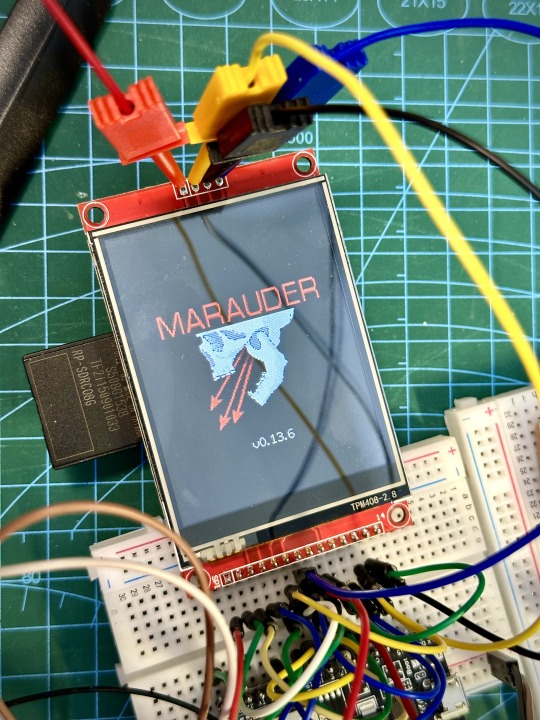
DIY: Marauder with Screen and GPS For Flipper Zero
Many of you would have seen the humongous ESP32 add-on module with touch screen and GPS for Flipper Zero shared in discussion groups, forums, etc. Well, this tutorial will provide you with all the information you need to build one yourself.
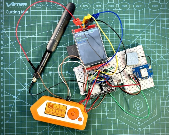
This build consists of mainly 4 parts. The TFT LCD 2.8" 240x320 SPI ILI9341 Touch Display cost me around US$5.50, the ESP32-WROOM-32U module cost around US$3, the NEO-6M GPS module cost around US$2.20 and an 8dbi 2.4GHz Wifi Antenna which cost around US$2. All of these parts can be easily found in online marketplaces like Aliexpress, Amazon, etc. Here is how you need to wire them up together. How you wish to lay this out or mount on a prototyping board is entirely up to you. As long as the connections are correct, you are good to go. The GPS module is optional, and mainly, it's used for the war driving functionality.
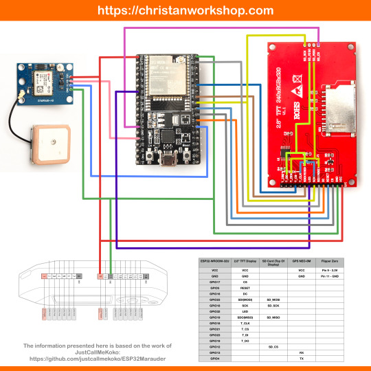
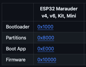
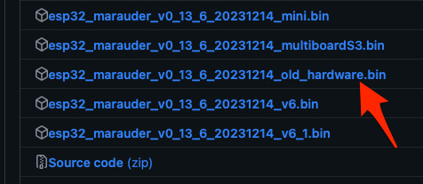
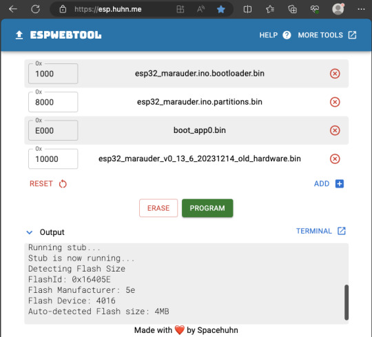
Next, you need to download all the firmware needed from here. Please download the Bootloader, Partitions, Boot App and Firmware files for v4 (Yes, v4 files, not any others) and save it on your computer.
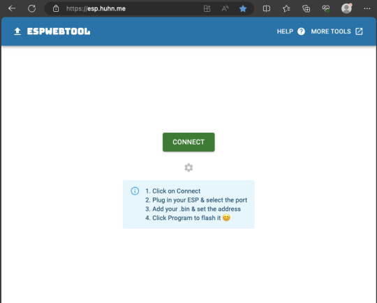
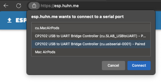
Now, press and hold the BOOT button on your ESP32-WROOM-32U module and connect it to your computer using a data-capable USB cable (some USB cables can only charge), then let go the BOOT button. Open Google Chrome or Microsoft Edge browser and go to ESPWebTool. Click the CONNECT button, then select the ESP32 usb serial connection. It should look something like below but can vary a little between different computers and operating systems.
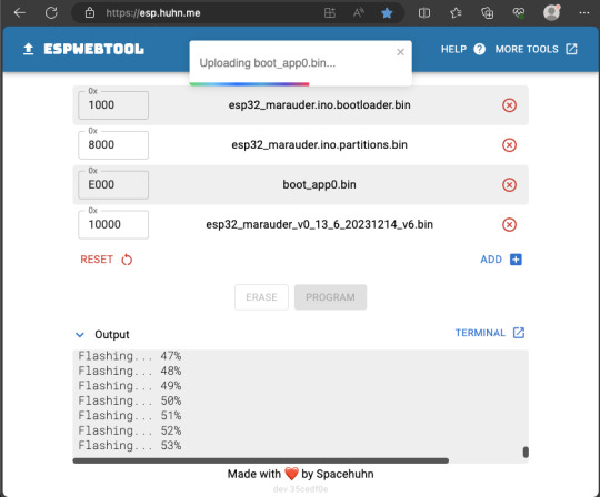
Select the firmware files for each slot exactly like below (take note of the 0x1000, 0x8000, etc. and their corresponding .bin files), then hit the PROGRAM button.
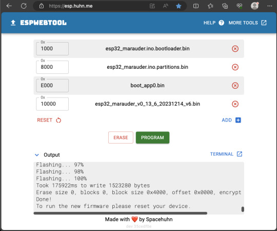
When completed successfully, you can unplug the USB cable from the ESP32 module and now you can connect your Marauder module to your Flipper Zero. Please ensure that your Flipper Zero is turned off before you connect it, and also turn off your Flipper Zero before disconnecting it. The 3.3V pin is also used by your Flipper Zero's SD card reader and connecting/disconnecting external modules that use this pin while the Flipper Zero is on can potentially corrupt the SD card. So, if everything went according to plan, your Marauder module should boot up and everything should look like below.
NOTE: If your Marauder boots up, but when you try to touch the screen and get no response, try tapping around the bottom part of your screen and see if the touch panel seems to be in inverted position from the actual display. Should this happen to you, just flash your ESP32 module again following the steps above, but use the v6 firmware. This should resolve the issue.
In this build, I just prototyped this on breadboard, but you can of course make it permanent by soldering it on to a prototype board and 3D print a case for it. This setup is essentially just using the Flipper Zero as a battery pack, instead of using the Flipper Zero to control Marauder. The large screen does make some things easier to do, compared to the small screen of the Flipper Zero, and there may be some functionality (not much) that is not currently in the Flipper Zero Marauder companion app. Here is a video showing the different menus in Marauder.
Personally, I don't think I will actually want to bring something so big around with me, along with my Flipper Zero. I think what makes Flipper Zero special is just how compact it is and all the different functionality cramped into it. This would probably be better off as a standalone unit by just hooking up a battery, but that's just me. Well, that's it for this tutorial. I hope you found this helpful.
Here's a good intro to Marauder if you are unfamiliar.
youtube
18 notes
·
View notes
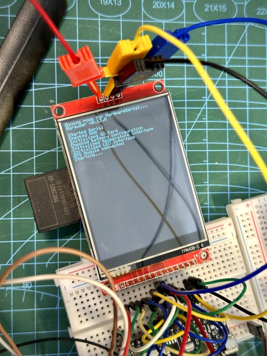
Text
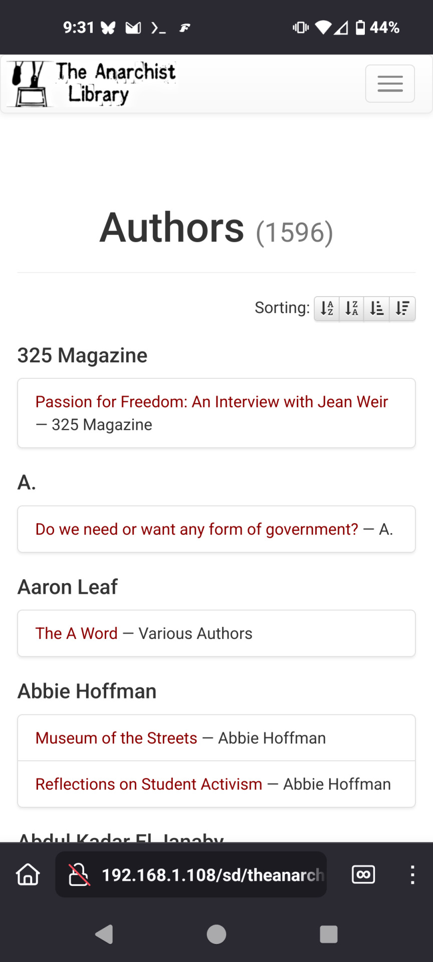
The test worked, after a bit of tweaking you can browse and read from the anarchist library off the esp32 transceiver boards were using and it even loads the fonts, css etc
69 notes
·
View notes
Text
Playable version of The Witness on a Protogen. (ESP32 Connected via LAN)
5 notes
·
View notes
Text
13. April 2024
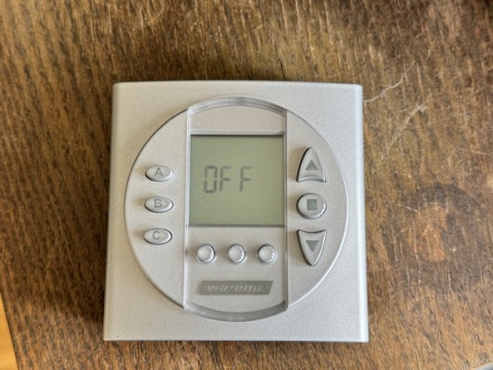
Die smarte Jalousie
Wir haben eine elektrische Jalousie. Die hält im Sommer die Sonnenwärme draußen und im Winter hat man etwas Sichtschutz und so. Dazu gibt es eine Fernbedienung. Damit ist es leicht, die Jalousie rauf- und runterfahren zu lassen. Weil wir vor ein paar Jahren, als die ganze Technik installiert wurde, auch etwas automatische Steuerung haben wollten, gab es seinerzeit auch eine Schaltuhr dazu.
Ich behaupte, dass ich mich eigentlich nicht besonders dumm anstelle, wenn es darum geht, so eine Schaltuhr zu programmieren. Aber dieses Gerät ist eine einzige Katastrophe. Bis heute ist es mir nicht gelungen, die so zu programmieren, dass die Jalousie dann herauf- und hinunterfährt, wenn sie soll. Zwar meistens, aber nicht zufriedenstellend. Wenn sie einmal funktionierte: Bloß nicht mehr anrühren, bis der Übergang von Sommer zu Winter und umgekehrt Maßnahmen verlangten. Das ist der Übeltäter, hier inzwischen inaktiv:
Zwischenzeitlich übernimmt Apple Homekit einige Funktionen in unserem Haus, z. B. die Steuerung der Warmwasserpumpe. Und da dachte ich, dass ich die Jalousie dort auch andocken könnte. Geht ja auch mit Funk und so. Aber leider ist es etwas undurchschaubar, was man nun für Gerätschaften braucht. Der Hersteller scheint nicht nur bei seinen Bedienungsanleitungen zur Verwirrung zu neigen. Ich bin mir also nicht sicher, ob die Steuerung überhaupt mit Apple Homekit gehen würde.
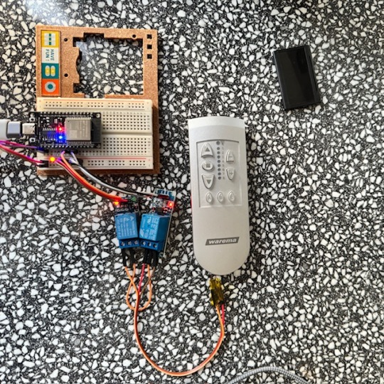
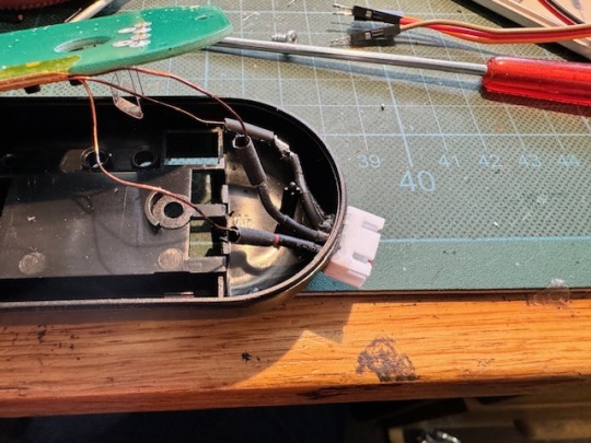
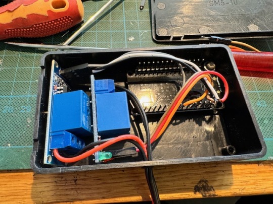
Also suche ich im Internet nach anderen Lösungen. Ein bisschen kann ich mit Arduinos umgehen, und so finde ich eine Lösung, wie man ein ESP32-Board mit Apple Homekit verheiraten kann. Meine Idee: Ich schalte mit dem ESP32 ein paar Optokoppler oder Relais, die so tun, als ob sie die Knöpfe an der Fernbedienung meiner Jalousie drücken. Dafür muss ich allerdings erst mal ziemlich filigrane Drähtchen an den richtigen Stellen der Platine anlöte. Diese Kontakte sind mit den Tastern auf der Platine verbunden.

Die Kupferlackdrähte enden dann an zwei Relais am ESP32-Board. Ich stecke das erst mal alles auf einer Steckplatine zusammen. Es funktioniert. Gegen Optokoppler entscheide ich mich, weil vermutlich die zu schaltende Spannung zu gering ist.
Meistens jedenfalls. Denn immer wieder verliert das ESP32-Board die Verbindung zum Homekit-Netzwerk. Auch hier ergoogle ich mir eine Lösung. Die besteht offenbar darin, dem WiFi-Router einen festen Kanal zuzuweisen. Ich hoffe, dass damit auch dasselbe Problem mit anderen Geräten passé ist, die sich ebenfalls immer mal wieder aus dem Verbund verabschieden.
Damit das alles besser nutzbar wird, kommt in die Fernbedienung der Jalousie eine Anschlussbuchse und das ESP32-Board mit den Relais in eine kleine Box, aus der das passende Verbindungskabel herausguckt.
Auf den Platinen der Relais befanden sich noch LEDs. Die habe ich aus Stromspargründen entfernt. Man sieht davon ja eh nichts.
Man kann nun die Knöpfe der alte Fernbedienung nach wie vor manuell bedienen, aber die Jalousien auch von der Home-App aus ereignis- oder zeitgesteuert herauf- und hinunter fahren lassen.

(Markus Winninghoff)
5 notes
·
View notes