#headers smd
Text
Reverse-engineered a serge gain cell that i have a while ago (and then found another person's schematic online, and they matched - good job us). Today i made a layout for it with smd parts. Here it is next to a DIL14 package for reference :3

I split the 8-pin header into two 4-pin headers, cause the one thing i dislike about ken stone style implementation is it's flimsily fixed to the board: it's one 8-pin header and an almost-square board sticking out perpendicular or laying parallel to the motherboard, IMO both options are unreliable unless you glue them up. So, two headers like this make sure that the board is securely fit to its motherboard.
Also this version has the power header rotated 90 degrees. There's a version where they are both vertical and yes the board looks prettier, but - think about it - serge designs always use a bunch of these, not one. So it makes sense to make it easier to run power through all of the gain cells like a skewer on one side, while breaking out the signal taps on the other side. It is a *slightly* less secure mount than two headers parallel, and definitely less pretty as a board, but i think it's good enough for such a huge improvement in board tracing ease.
VCFQ here i come!... next year probably
4 notes
·
View notes
Link
Features: B650M DS3H - AMD Socket AM5: Supports AMD Ryzen™ 7000 Series Processors - Unparalleled Performance: Direct 6+2+1 Phases Digital VRM Solution - Dual Channel DDR5: 4*SMD DIMMs with AMD EXPO™ & Intel® XMP Memory Module Support - SuperSpeed Storage: 2*PCIe 4.0 x4 M.2 Connectors - Advanced Thermal Design & M.2 Thermal Guard: To Ensure VRM Power Stability & 25110 M.2 SSD Performance - PCIe x16 EZ-Latch with Quick Release & Screwless Design - Fast Networks: 2.5GbE LAN - Extended Connectivity: 2*DP, HDMI, 2*USB-C® 10Gb/s - Smart Fan 6: Features Multiple Temperature Sensors, Hybrid Fan Headers with FAN STOP - Q-Flash Plus: Update BIOS Without Installing the CPU, Memory and Graphics Card UNPARALLELED PERFORMANCE With the fast-moving technology changes, GIGABYTE always follows the latest trends and provides customers with advanced features and latest technologies. GIGABYTE motherboards are equipped with upgraded power solution, latest storage standards and outstanding connectivity to enable optimized performance for gaming. Direct Digital VRM Design To ensure maximum Turbo Boost and overclocking performance of AMD's new generation CPU, GIGABYTE UD series motherboard equip the best VRM design ever built with the highest quality components. PCIe 4.0 Hardware Design GIGABYTE B650 Motherboards are ready to work with the PCIe 4.0 devices which are expected to experience twice bandwidth than the current PCIe 3.0 devices. To reach the high speed and maintain good signal integrity, GIGABYTE R&D uses the low impedance PCB to provide the maximum performance DDR5 EXPO & XMP Overclocking Up to 6400 and Beyond* AORUS is offering a tested and proven platform that the memory overclocking capability is able up to 6400 and beyond. All users need to do for achieving this extreme memory performance boost is to ensure that their DDR5 memory modules are AMD EXPO™/ Intel® XMP capable, the EXPO/XMP function is activated and enabled on their AORUS motherboard. *Memory overlocking and XMP profile support may vary depending on hardware configuration. Unlock DDR5 Voltage Shielded Memory Routing All memory routing is under the PCB inner layer shielded by a large ground layer to protect from external interference. EXPO and XMP Dual Support GIGABYTE AM5 MB supports both AMD EXPO™ and Intel® XMP overclocking memory modules for maximal compatibility. MB will automatically detect both profiles format in SPD, users can choose to enable one of profiles from BIOS menu and easily reach overclocked memory performance. DDR5 Auto Booster Automatically Boost the Native DDR5 frequency to 5000MHz while the system is under heavy loading by a single click. AMD EXPO™ and Intel® XMP 3.0 User Profile Define and create your own SPD profile into Native, AMD EXPO™ and Intel® XMP 3.0 memory modules. One user-defined profile can be saved, loaded either locally or from/to an external storage device. - One empty SPD profile can be defined by users and carry to next computer - Quick memory performance simulation based on user input clock and timing parameters - Profile save and load function to share your memory parameters online - SPD Re-defined or retrieve from database - Performance Simulation - Save/Load Profile - Overclocked Performance - Profile Clearance THERMAL DESIGN GIGABYTE Motherboards' unparalleled performance is guaranteed by innovative and optimized thermal design to ensure the best CPU, Chipset, SSD stability and low temperatures under full load application and gaming performance. Thermal Design Advanced Thermal Heatsinks Advanced thermal heatsinks to improve thermal efficiency with better airflow and heat exchange. M.2 Thermal Guard The M.2 Thermal Guard prevents throttling and bottlenecks from high speed M.2 SSDs as it helps to dissipate heat before it becomes an issue. 6-Layer & 2X Copper PCB 2X copper PCBs design effectively lower the component temperature by its high thermal conductivity and low impedance. SMART FAN 6 Smart Fan 6 contains several unique cooling features that ensure gaming PC maintain its performance while staying cool and quiet. Multiple fan headers can support PWM/DC fan and pump, and users can easily define each fan curve based on different temperature sensors across the board via intuitive user interface. High Current Support Each fan headers support PWM and DC fan and Water Cooling Pump , and up to 24W (12V x 2A) with Over-Current Protection Precision Control Multiple temperature/fan speed control points for precise fan curve Dual Curve Mode Slope/Stair dual mode for different user scenario Fan Stop Fan can stop completely below users' specified temperature point PWM/DC Fan Headers Internal Temperature Sensors Smart Fan 6 BIOS UI 1 - Improve fan curve UI - We increase control points from 5 to 7 and larger fan speed graph for precise and easier fan curve control. 2 - Slope/Stair dual graph mode - Fan curve can be quickly switch with Slope and Stair modes for different user scenario. Slope is traditional and intuitive linear fan speed curve. With newly added Stair non-linear mode, fan keeps at same speed between specified temperature interval. 3 - Manual Input - For advanced users, we provide fan speed manual input for more precise control. 4 - EZ Tuning - Use can place 4 EZ Tuning points at rough temperature/fan speed, and Smart Fan 6 can quickly generate a fan curve. 5 - Fan curve profile - Fan curve profile can be saved in BIOS ROM, profile will be kept after updating BIOS. Note: The picture is for reference and may vary by model. CONNECTIVITY GIGABYTE Motherboards enable the ultimate connection experience with blazing data-transfer speeds through the next generation network, storage. First adopter on 2.5GbE LAN onboard 2X Faster than ever - Adoption of 2.5G LAN provide up to 2.5 GbE network connectivity, with at least 2 times faster transfer speeds compared to general 1GbE networking, perfectly designed for gamers with ultimate online gaming experience. - Support Multi-Gig(10/100/1000/2500Mbps) RJ-45 Ethernet Connecting the Future - USB 3.2 Gen 2 Type-C® The USB 3.2 Gen 2 ports provide with speeds up to 10Gbps. With twice the bandwidth compared to its previous generation as well as backwards compatibility with USB 3.2 Gen 1 and USB 2.0, the much-improved USB 3.2 Gen 2 protocol is available over the new reversible USB Type-C™ and the traditional USB Type-A connector for better compatibility over a wider range of devices. Hi-Fi Audio High-End Audio Capacitors GIGABYTE motherboards use high-end audio capacitors. These high quality capacitors help deliver high resolution and high fidelity audio to provide the most realistic sound effects for gamers. Audio Noise Guard GIGABYTE motherboards feature an audio noise guard that essentially separates the board's sensitive analog audio components from potential noise pollution at the PCB level. PERSONALIZATION GIGABYTE motherboards bundle several useful and intuitive software to help users to control every aspect of motherboard and provide customizable lighting effect with outstanding aesthetics to fit your unique personality. RGB Fusion Multi-Zone Light Show Design Now offering more LED customizations than ever, users can truly adapt their PC to represent their lifestyle. With full RGB support and a redesigned RGB Fusion 2.0 application, the user has complete control over the LEDs which surround the motherboard. UEFI BIOS Friendly User Interface The EASY MODE shows important hardware information in one page including CPU clock, Memory, Storage, Fan. My Favorites Add constantly used items into the favorite menu for quick access. Storage Information Show all kinds of storage information including SATA, PCIE and M.2 interface. Changelog List all changes before saving and exiting bios. Quickly review overall settings modification. Intuitive Load Line Curve Clearly show each loadline calibration setting in an intuitive curve graph. GIGABYTE CONTROL CENTER GIGABYTE CONTROL CENTER (GCC) is a unified software for all GIGABYTE supported products. It provides newly designed intuitive user interface to control all essential function. - Unified software platform for all Gigabyte supported products - Intuitive user interface for an eased experience - Modularized control components only for installed hardware - Auto update function to keep system up to date and support future products Multi-key A multi-function reset button that can be reconfigured to other function in BIOS for different user scenarios. RGB Switch Turn off all lighting effect on motherboard. Direct-To-BIOS Boot into BIOS menu directly without pressing any keyboard button. Safe Mode Boot into BIOS safe mode to change specific option without losing other BIOS settings. * Photo for reference only. ULTRA DURABLE GIGABYTE Ultra Durable™ design provides product durability and high-quality manufacturing process. GIGABYTE motherboards use the best components and reinforce every slots to make each of them solid and durable. DIY Friendly Q-Flash Plus Update the BIOS easily without installing the CPU, memory and graphics card. With GIGABYTE Q-Flash Plus, you don't need to install the CPU, memory and graphics card nor enter the BIOS menu to flash the BIOS. Just download and save a new BIOS file (rename to gigabyte.bin) on the USB flash drive, then press the dedicated Q-Flash Plus button and you're good to go! Specifications: CPU AMD Socket AM5, support for: AMD Ryzen™ 7000 Series Processors (Please refer "CPU Support List" from Gigabyte's website for more information.) Chipset AMD B650 Memory Support for DDR5 6400(OC) / 6200(OC) / 6000(OC) / 5600(OC) / 5200 / 4800 / MT/s memory modules 4 x DDR5 DIMM sockets supporting up to 128 GB (32 GB single DIMM capacity) of system memory Dual channel memory architecture Support for non-ECC Un-buffered DIMM 1Rx8/2Rx8/1Rx16 memory modules Support for AMD EXtended Profiles for Overclocking (AMD EXPO™) and Extreme Memory Profile (XMP) memory modules (Please refer "Memory Support List" from Gigabyte's website for more information.) Onboard Graphics Integrated Graphics Processor: 2 x DisplayPorts, supporting a maximum resolution of 3840x2160 @ 144 Hz * Support for DisplayPort 1.4 version and HDR. 1 x HDMI port, supporting a maximum resolution of 4096x2160 @ 60 Hz * Support for HDMI 2.1 version and HDCP 2.3. ** Support native HDMI 2.1 TMDS compatible ports. (Graphics specifications may vary depending on CPU support.) Support for up to 3 displays at the same time Audio Realtek® Audio CODEC High Definition Audio 2/4/5.1/7.1-channel * You can change the functionality of an audio jack using the audio software. To configure 7.1-channel audio, access the audio software for audio settings. LAN Realtek® 2.5GbE LAN chip (2.5 Gbps/1 Gbps/100 Mbps) Expansion Slots CPU: 1 x PCI Express x16 slot, supporting PCIe 4.0 and running at x16 (PCIEX16) Chipset: 1 x PCI Express x1 slot, supporting PCIe 3.0 and running at x1 (PCIEX1) Storage Interface CPU: 2 x M.2 connectors (Socket 3, M key, type 25110/2280 PCIe 4.0 x4/x2 SSD support) Chipset: 4 x SATA 6Gb/s connectors RAID 0, RAID 1, and RAID 10 support for NVMe SSD storage devices RAID 0, RAID 1, and RAID 10 support for SATA storage devices USB CPU: 1 x USB Type-C® port on the back panel, with USB 3.2 Gen 2 support 1 x USB 3.2 Gen 2 Type-A port (red) on the back panel CPU + USB 2.0 Hub: 4 x USB 2.0/1.1 ports on the back panel Chipset: 1 x USB Type-C® port with USB 3.2 Gen 2 support, available through the internal USB header 4 x USB 3.2 Gen 1 ports (2 ports on the back panel, 2 ports available through the internal USB header) 4 x USB 2.0/1.1 ports available through the internal USB headers Internal I/O Connectors 1 x 24-pin ATX main power connector 1 x 8-pin ATX 12V power connector 1 x CPU fan header 3 x system fan headers 1 x addressable LED strip header 1 x RGB LED strip header 2 x M.2 Socket 3 connectors 4 x SATA 6Gb/s connectors 1 x front panel header 1 x front panel audio header 1 x USB Type-C® header, with USB 3.2 Gen 2 support 1 x USB 3.2 Gen 1 header 2 x USB 2.0/1.1 headers 1 x Trusted Platform Module header (For the GC-TPM2.0 SPI/GC-TPM2.0 SPI 2.0 module only) 1 x serial port header 1 x reset button 1 x reset jumper 1 x Clear CMOS jumper Back Panel Connectors 4 x USB 2.0/1.1 ports 1 x PS/2 keyboard/mouse port 2 x DisplayPorts 1 x HDMI port 1 x USB 3.2 Gen 2 Type-A port (red) 1 x USB Type-C® port, with USB 3.2 Gen 2 support 1 x Q-Flash Plus button 1 x RJ-45 port 2 x USB 3.2 Gen 1 ports 3 x audio jacks I/O Controller iTE® I/O Controller Chip H/W Monitoring Voltage detection Temperature detection Fan speed detection Fan fail warning Fan speed control * Whether the fan speed control function is supported will depend on the cooler you install. BIOS 1 x 256 Mbit flash Use of licensed AMI UEFI BIOS PnP 1.0a, DMI 2.7, WfM 2.0, SM BIOS 2.7, ACPI 5.0 Unique Features Support for GIGABYTE Control Center (GCC) * Available applications in GCC may vary by motherboard model. Supported functions of each application may also vary depending on motherboard specifications. Support for Q-Flash Support for Q-Flash Plus Bundled Software Norton® Internet Security (OEM version) LAN bandwidth management software Operating System Support for Windows 11 64-bit Support for Windows 10 64-bit Form Factor Micro ATX Form Factor; 24.4cm x 24.4cm Manufacturer Part No: B650M DS3H Brand: Gigabyte Product Type: mATX Motherboard UPC 889523034231 Product Family: - Shipping Weight: 1.45 kg PB Part No: MBDGBM36503 Product Model: B650M DS3H Warranty: 36 months * * Warranty period is as stated above unless the manufacturer has chosen to specify a longer period. All warranties are return to base unless otherwise specified. Why is there a reasonable price displayed? Discover the reason behind our incredibly reasonable prices! At our company, we prioritize your satisfaction and work tirelessly to offer you access to top-notch brands without breaking the bank. Our commitment to minimizing profit margins enables us to deliver affordability without compromising on quality. Shop with confidence and explore a wide range of reputable products at budget-friendly rates. Your satisfaction is our priority! #
0 notes
Text
Arduino Uno R3 SMD Atmega328P IC

Are you looking for a reliable and feature-rich microcontroller for your electronics projects? The Arduino Uno R3 SMD Atmega328P IC is a top choice for hobbyists, makers, and professionals alike.
The Arduino Uno R3 SMD Atmega328P IC is a compact and lightweight microcontroller that is perfect for portable projects. It features a powerful Atmega328P processor and a range of input and output capabilities, making it a versatile and reliable choice for a wide range of applications.
Some of the key features of the Arduino Uno R3 SMD Atmega328P IC include:
Surface Mount Device (SMD) design: This compact design allows for a smaller and more lightweight microcontroller, making it ideal for portable projects.
Atmega328P processor: The Atmega328P is a high-performance processor with a maximum clock speed of 16 MHz, providing fast and reliable performance.
Wide range of input and output capabilities: The Arduino Uno R3 SMD Atmega328P IC has 14 digital input/output pins, 6 analog inputs, and a number of other features such as a USB connection, a power jack, and an ICSP header.
Extensive support and community: The Arduino platform has a large and active community of developers and users, providing extensive resources and support for projects using the Arduino Uno R3 SMD Atmega328P IC.
Whether you are a beginner or an experienced electronics enthusiast, the Arduino Uno R3 SMD Atmega328P IC is a great choice for your next project. Shop now and start building your masterpiece today!
To code for the Arduino Uno R3 Ch340G USB IC SMD Atmega328P IC, you will need to follow these steps:
Install the Arduino Integrated Development Environment (IDE) on your computer. This is a free software tool that you will use to write and upload code to your Arduino board.
Connect your Arduino board to your computer using a USB cable.
Open the Arduino IDE and select the correct board type and serial port in the "Tools" menu. For the Arduino Uno R3 Ch340G USB IC SMD Atmega328P IC, select "Arduino/Genuino Uno" as the board type and the appropriate serial port for your board.
Write your code in the Arduino IDE. The Arduino programming language is based on C++ and has a number of built-in functions for controlling the board's hardware.
Test your code by using the "Verify" button in the Arduino IDE. This will check your code for any syntax errors.
Upload your code to the Arduino board by clicking the "Upload" button in the Arduino IDE. This will send your code to the board, where it will be executed.
If you encounter any errors or issues while uploading your code, check the Arduino IDE's output window for any error messages. You may also need to troubleshoot your board's connection or other hardware issues.
0 notes
Photo


Icons Ana Jacobs
Se pegar alguma coisa, por favor credite meu user ( @SoMeuDaleste ) no Twitter.
#SMD#SMD Design#smd designs#headers smd#smd icons#icons#icon#icones#tumblr icons#icons tumblr#icons models#icons morenas#icons moças#icons meninas#icons mc#icons meninas tumblr#tumblr icons meninas#icons meninos loiros#icons menina tumblr#icons mulheres tumblr#tumblr icons mulheres#tumblr icons morenas#icons morenas tumblr#icons girls#icons girl#icons gilrs#icons girl tumblr#tumblr icons girl#icons famosas#icons fake tumblr
2 notes
·
View notes
Photo

That moment when you're out of ceramic caps for your breadboard but have some 1206 SMD caps laying around. #breadboard #electronics #throughhole #smd #capacitor #header #pins #soldering #1206
4 notes
·
View notes
Video
instagram
We are always surprised by the little projects @maker.moekoe comes up with! Make sure to check out his feed!! - - Posted @withrepost • @maker.moekoe 5/6 ✅ yep, the #pikocube is already lit 😁🎲 I‘m very excited about the last wall/pcb, cause it could get hard to remove them once soldered 😅 the lipo will sit inside the cube at the end 👍🏻 I am currently doing some research for the next revision, maybe I will use a super cap instead of a normal lipo... what do you think? wireless charging is a must have for the next revision 👌🏻 . . the cube can be programmed via a row isp header sitting on the outside like shown in the end of this video 😬 it is a diy programming adapter with six #pogopins 😋 . . . #ledcube #leddice #led #ws2812 #neopixel #soldering #pcb #pcbassembly #iot #internetofthings #printedcircuitboard #circuit #smd #esp8266 #esp32 #mcu #arduino #electroniclovers #electronics #mcu #opensource #engineering #tech #technology #diyelectronics #doityourself #diy #moekoe_diy (at Busan, South Korea) https://www.instagram.com/p/B69pQW_HAuf/?igshid=6tdbovrl0wpc
#pikocube#pogopins#ledcube#leddice#led#ws2812#neopixel#soldering#pcb#pcbassembly#iot#internetofthings#printedcircuitboard#circuit#smd#esp8266#esp32#mcu#arduino#electroniclovers#electronics#opensource#engineering#tech#technology#diyelectronics#doityourself#diy#moekoe_diy
1 note
·
View note
Video
undefined
tumblr
Electronic components and very hard to find parts. All your electrical parts in one place.
Brands and parts supplier. TI, GE,
Yaskawa, Honeywell, Eaton, Rockwell parts, Siemens, ABB, allen Bradley, siemens, Omron,
All In One Components sells: Active components, passive components, all in one components, hard to find parts distributor, distributor of obsolete parts, distributor of components, obsolete parts distributor, electronics distributor, electronics components distributor, components distributor, obsolete electronics, obsolete electronic parts, obsolete components, components, hard to find parts, electronic components, obsolete parts, Resistor, Capacitor, Microcontroller, Inductor, Transformer, Battery, Fuse, Diode/LED, Diode, Transistors, Integrated Circuit, Relays, Switches, Motors, Circuit Breakers, LCD, quote, motorola, quality, relays, sale, audio, directory, component, types electronic, integrated circuits, ics, excess, relays, switches, products, protection, spec, optoelectronics, diodes, parts source, led, socket cable, wire, assemblies, electronics, cable connectors, wire, cable, leds, switches, capacitor, resistor, supplies, quote, request, quality, specials, obsolete, distributor electronic, network, molex, source, semiconductors, connectors, cables, ceramic, call us, electronic, power, electric, source electronic components, semiconductors, resistors, diode, electronic component parts, electronic components, transistors, electrical, source, shop, connectors, manufacturers, electronic, component, capacitors, services, displays, semiconductor, tools, passive components, components store, wide, buy electronic, distributors, hard find, panasonic, fixed, manufacturing, prices, component types, electronic components, components plus, types electronic components line, parts, directory component types, electronic components line card, fuses, need, part search, parts, popular parts, leading, board, control, quality, new, batteries, hyperlinecard, hot parts, popular, sourcing, best, alphabetized parts directory, component parts industry, well, brands, raw materials, needs obsolete, hard find, adhesives, rf, microtemp g4a01, kte fan switch, jsu21x126aqb, e127584, kedu hy56, e185116, joemex, joemex 74 series, TI, GE, yaskawa, honeywell, eaton, rockwell parts, siemens, ABB, Allen Bradley, Siemens, Omron, Schneider, electronic components, list of components, active components, passive components, obsolete electronic parts, obsolete components, components, hard to find parts, electronic components, obsolete parts, resistor, capacitor, micro controller, inductor, transformer, battery, fuse, diode/LED, diode, transistors, integrated circuit, relays, switches, motors, circuit breakers, LCD, power supply units, laptop screen replacement parts, resistors, photo-boards, headers, switches, photo-resistors, voltage regulator, ic sockets, laser diode, gunn diode, pin diode, tunnel diode, varactor diode,step recovery diode,schottky diode, zonor diode,smd diode, motherboard components, omron electronic components, velocity electronics, soldering electronic equipment, circuit board parts, power modules, electromechanical, wireless connectivity sensors, custom magnetics, custom connectors, flex rigid, microvia HDI.
1 note
·
View note
Text
An 8-digit DIP switch
An 8-digit DIP switch, from left to right 1~8, the maximum value can reach 128, when the switch is not dialed, the state of the switch is all up, that is, on the ON/DP side, when the DIP switch is close to Female header the number When one side is in the down state, then the corresponding relationship between the numbers on the switch and the actual decimal number will be explained in detail.
1. If you want to dial the number 1, you can directly dial the 1 on the switch, because from the figure, it can be seen that 1 corresponds to the zero power of 2, and the zero power of 2 is equal to 1 in decimal.
2. If you want to dial the number 10, you can dial down 2 and 4 on the switch. As can be seen from the figure, 2 corresponds to the first power of 2, which is equal to 2 in decimal; 4 corresponds to the third power of 2, which is equal to decimal. Of 8; 2+8=10
DIP switch, patch switch, rotary coding switch, program switch, dial key switch, dial code switch, coding switch, toggle switch, overclocking switch, address switch, dial switch, digital switch, SMT switch, SMD switch, DIP switch, DIP switch, DIP Switch.
1. Flat dip DIP switch (DS series): 2 positions, 3 positions, 4 positions, 5 positions, 6 positions, 7 positions, 8 positions, 9 positions, 10 positions, 12 positions;
2. Key type DIP switch (DP series): 2, 3, 4, 5, 6, 7, 8, 10, 12;
3. Right-angle DIP switch (DA series): 2 positions, 3 positions, 4 positions, 5 positions, 6 positions, 7 positions, 8 positions, 9 positions, 10 positions;
4. IC type DIP switch (DI series): 2 positions, 3 positions, 4 positions, 5 positions, 6 positions, 7 positions, 8 positions, 10 positions, 12 positions;
5. SMD DIP switches (SMD series): 2 digits, 3 digits, 4 digits. 5 digits, 6 digits, 7 digits, 8 digits, 10 digits, 12 digits;
6. Rotary DIP switch (RS series): 16-bit rotary encoder switch, 10-bit rotary DIP switch;
● 1. Mechanical characteristics:
1. Operating force: 800g max
2. Push button stroke: 2.00mm
3. Operating temperature: -20℃~+70℃
4. Storage temperature: -40℃~+85℃
● 2. Material:
1. Base: engineering plastic, black
2. Upper cover: engineering plastic, red, blue
3. Push button: engineering plastic, white
4. Terminal: Alloy copper plated with gold.
● Three, electrical characteristics:
1. Electrical life: Each switch is tested under the voltage of 24VDC and current of 25mA, and it can be toggled back and forth 2,000 times.
2. The rated current of the KingTek switch that does not switch frequently: 100mA, withstand voltage 50VDC.
3. The rated current that the switch frequently switches: 25mA, withstand voltage 24VDC.
4. Contact impedance: (a) the initial value is 50mΩ at the maximum, (b) the maximum value is 100mΩ after the test.
5. Insulation resistance: minimum 100MΩ, 500VDC.
6. Compressive strength: 500VAC/1 minute.
7. Interpolar capacitance: 5pF max.
8. Circuit: single contact single selection
0 notes
Text
ARDUINO UNO REV3 SMD
ARDUINO UNO REV3 SMD
ARDUINO UNO R3 SMD Description:
The Arduino Uno is a microcontroller board based on the ATmega328. It has 14 digital input/output pins (of which 6 can be used as PWM outputs), 6 analog inputs, a 16 MHz ceramic resonator, a USB connection, a power jack, an ICSP header, and a reset button. It contains everything needed to support the microcontroller; simply connect it to a computer with a USB cable…

View On WordPress
0 notes
Link
DSO138mini brings in the following improvements: Better structure and smaller size. The bulky pin-headers connecting the LCD and main board in old DSO138 has been eliminated. The soldering ...
0 notes
Text
Lesson learned: check the power
#electronics #esp8266 Lesson learned: check the power
The PCBs arrived from the fab house and I was impatient to try them out.
They’re nothing clever – just a way of saving a bit of wiring for my ESP8266-based IoT room thermometer. Aside from headers, there are just four components (not including the pullup resistor I don’t need anymore because I made a mistake).
I hand-solderedon the three 1206 SMD resistors and one 1206 SMD capacitor and added all…
View On WordPress
1 note
·
View note
Text
Microchip tung “chiến binh” mới: Mô-đun vi điều khiển đầu tiên cho thiết bị ngoại vi
Đây là mô-đun vi điều khiển Wifi đầu tiên với định danh đơn nhất, có thể kiểm tra, hỗ trợ nền tảng Trust&GO của Microchip. Đồng thời, cung cấp chức năng MCU mạnh mẽ, được kích hoạt sẵn cho các nền tảng điện toán đám mây hàng đầu thị trường cùng định danh có thể kiểm tra được.
Đối với những nhà phát triển đang thiết kế các hệ thống IIoT, WFI32E01PC có mức độ tích hợp cao của Microchip là một mô-đun MCU Wifi hỗ trợ nền tảng Trust&GO an toàn và được kích hoạt sẵn cho các nền tảng điện toán đám mây.
WFI32E01PC thoả mãn được yêu cầu của các nhà tạo mẫu về một giải pháp mô-đun có mức độ tích hợp cao với khả năng cung cấp chức năng MCU ở cấp độ công nghiệp, kết nối Wi-Fi ổn định cùng chức năng bảo mật và xác thực phần cứng.

Thiết bị WFI32E01PC-I được mang lại với sản lượng lớn với giá khởi điểm từ 8,14$.
Ông Steve Caldwell, Phó chủ tịch phụ trách bộ phận Kinh doanh Giải pháp Không dây của Microchip chia sẻ: “Khi số lượng các vụ tấn công ngày càng gia tăng, giải pháp mã hóa dữ liệu phần mềm truyền thống không còn đủ để bảo vệ dữ liệu đang được truyền tải nữa. Đây là MCU đã được kích hoạt sẵn, an toàn dầu tiên với kết nối Wi-Fi được mang lại trực tiếp từ nhà máy hoặc thông qua hệ thống phân phối.”
Không giống với những thiết bị đã xuất hiện trước đây, công nghệ mới của Microchip bao gồm 1 lõi MCU PIC32 cao cấp, nhiều thiết bị ngoại vi và một nền tảng bảo mật phần cứng đã được kiểm chứng – không chỉ cung cấp kết nối Wi-Fi mà còn giữ vai trò như là một lõi MCU mạnh mẽ của toàn bộ hệ thống IIoT.
Khi Internet đã đóng một phần rất lớn vào đời sống, thoát khỏi phạm vi tự động hóa nhà riêng và thâm nhập sâu hơn và lĩnh vực điều khiển tòa nhà – bao gồm cả hệ thống Sưởi ấm, Thông khí và Điều hòa không khí cửa ga – ra, quạt và đang tăng trưởng trong các ứng dụng tự động hóa tòa nhà và công nghiệp khác, nhu cầu về kết nối IoT công nghiệp tin cậy và an toàn cũng cao hơn lúc nào hết.
WFI32E01PC tự hào là sản phẩm tuân thủ tiêu đúng kỹ thuật của WFA (Wi-Fi Alliance – Liên minh Wi-Fi) và nhận được chứng nhận toàn diện của những đơn vị quản lý dưới đây trên thế giới: FCC (Ủy ban Truyền thông Liên bang), IC (Industry Canada) và RED (Nghị định về thiết bị vô tuyến Châu Âu).

Ngoài các ứng dụng công nghiệp lớn, WFI32E01PC còn được gia công dành cho các thiết bị tự động hóa nhà riêng, thiết bị điện toán và thiết bị tiêu dùng đáp ứng hầu hết tất cả mọi nhu cầu về công nghệ wifi từ không gian quy mô nhỏ đến quy mô “siêu khổng lồ”.
Microchip cung cấp một danh mục đa dạng để tối giản hóa các hệ thống IoT và IIoT khi kết hợp mô – đun WFI32E01PC với các linh kiện hàng đầu thị trường khác của Microchip như: loại sản phẩm Ethernet PHYs KSZ8081, máy thu phát CAN MCP2542WFD, các cảm biến và công nghệ vô tuyến bao gồm cả Bluetooth® Low Energy (BLE), Long Range (LoRa®) và IEEE® 802.15.4.
WFI32E01PC của Microchip được hỗ trợ bởi PIC32MZW1 Curiosity Board. Microchip cung cấp nhiều lựa chọn về hỗ trợ phần cứng và phần mềm. Hỗ trợ phần mềm bao gồm Môi trường phát triển tích hợp (Integrated Development Environment – IDE) MPLAB® X của Microchip và Khung phát triển phầm mềm tích hợp MPLAB Harmony v3. Các công cụ hỗ trợ bao gồm trình gỡ lỗi (debugger) on-board và phần header lập trình nối tiếp trong mạch điện dành cho MPLAB Snap, MPLAB PICkit™ 4 hoặc công cụ lập trình/gỡ lỗi bên ngoài MPLAB ICD 4.
Microchip đã sẵn sàng tung “chiến binh” WFI32E01PC-I (54-pin SMD 24.5 x 20.5 x 2.5 mm) ra thị trường với hơn 10.000 sản phẩm trong khoảng thời gian tới.
Nguồn: genk
Bài viết Microchip tung “chiến binh” mới: Mô-đun vi điều khiển đầu tiên cho thiết bị ngoại vi đã xuất hiện đầu tiên vào ngày Đồ Chơi Công Nghệ.
source https://dochoicongnghe.com.vn/microchip-tung-chien-binh-moi-mo-dun-vi-dieu-khien-dau-tien-cho-thiet-bi-ngoai-vi-22903.html
0 notes
Photo


Icons Ana Jacobs II
Se pegar alguma coisa, por favor credite meu user ( @SoMeuDaleste ) no Twitter.
#SMD#SMD Design#smd designs#headers smd#smd icons#icons#icon#icones#tumblr icons#icons tumblr#header#headers#tumblr headers#headers tumblr#headers random#tumblr#wallpaper tumblr#girl icons tumblr#icons tumblr girl#meninas icons tumblr#icons tumblr morenas#meninas tumblr icons#tumblr icons meninas#tumblr icons girl#tumblr icons morenas#icons loiros#icons loiras#icons loiras tumblr#icons tumblr loiras#tumblr icons loiras
1 note
·
View note
Text
A Tiny Failure

If you are a regular visitor of my blog, you might know that (with a few exceptions) I've been posting a new blog posts every two weeks. Unfortunately I skipped this regular update last week, because I've been a little bit sick. Nothing major, but I didn't want to contaminate my boxes of SMD components with germs. So after a few days of sleep it's time to get back to business and start with something small. Literally.
Due to my mandatory rest, I haven't had the time to work on something interesting to blog about. Of course this happens every once in a while, and so my usual solution is to just go through my recent Ali Express deliveries, to see if there is something I can either get up and running, or kill with some magic smoke.

Soon I found a suitable candidate: the ATTiny10. This tiny guy contains a 12Mhz 8-bit micro controller with 1024 bytes of flash memory and 32 bytes of ram. Of course a micro controller is a bit boring without any in- or output, so i wanted to combine it with an other recent delivery: A WS2812B addressable RGB led in a 2020 package. Together with some 0.2mm enameled wire this can be a pretty fascinating micro-project.

To make the soldering a bit doable, I put some kapton-tape on my workbench, sticky side up. This allows me to keep both component in place while I try to reach the limit of my soldering skills.

First, let's connect some wires to the ATTiny10. With a macro lens in front of my iPhone's camera, it looks like it's huge. Unfortunately it's still roughly the size of my soldering iron's tip.

Let's start the surgery. Please be quiet, and don't breath to much or else we need to start all over again.

After a few burned fingers, too much soldering flux and to my own surprise I managed to connect wires to all six pins.

And a few minutes later, I managed to solder the WS2812 as well. Just a few more soldering joints and the programming header will be connected as well. This should allow me to program the ATTiny10 using the USBasp programmer.

And here it is! The end result! An illuminated led! Great isn't it?! OK! See you next time!

Ok, ok. I'm going to be honest here. The reason the LED is illuminated is just because I managed to add some "noise" data on the data line when I touched the micro controller while it was powered on. So nothing more than a lucky shot.
Of course I still need to program the ATTiny. But here's the catch: It turns out the ATTiny isn't supported by PlatformIO. So I had to revert back to the dreadful Arduino IDE.

David Johnson-Davies wrote a nice post on how to program the ATTiny10 and even supplied the necessary files needed to do so using the Arduino IDE. But as you can see, in the screenshot above, I ran into an error.
Now, to be honest I don't know what causes this issue. It might be one of the following:
The USBasp I'm using is damaged or doesn't support the necessary TPI protocol. (Unlikely)
The ATTiny isn't connected correctly, maybe do to a bad soldering connection. (Still a bit unlikely)
I overheated and damaged the ATTiny when I soldered the connections. (Sounds a bit more likely)
I'm doing something wrong with the software. (Sounds likely)
I'm still not fully recovered and missing something completely obvious. (99% sure this is it)
Of course I could have spent a week trying to solve this. But that would mean yet an other quiet week on my blog. So, instead I just end this write-up with a big anti-climax.

If I'm able to solve this issue in the coming two weeks, I'll report back in my next blog. If you have any suggestions or pointers to a solution, leave them in the comments down below.
PS. Still looking for something awesome? Make sure to check this.
5 notes
·
View notes
Video
youtube
How to simulate create g code solidcam solidworks
==================
Please subscribe our channel, thanks
For modification please contact us, thanks
Please visit, thanks
Entertainment for Engineer's break time
Rixtronix LAB Channel
https://www.youtube.com/channel/UC89se0BZ2oGeqN5jNbDAyQQ
Rixtronix LAB is looking for local engineering bussiness partner, please contact us, thanks
Rixtronix LAB 正在寻找当地工程业务合作伙伴,请与我们联系,谢谢
Please share a coffee with me, thanks...
Motherboard Capacitors 1800uF 16V low ESR
https://www.ebay.com.au/itm/173840921403
Motherboard Capacitors 1000uF 16V low ESR
https://www.ebay.com.au/itm/173841745704
Arduino Uno R3 Brand NEW
https://www.ebay.com.au/itm/173828695857
Arduino Mega 2560 Brand NEW
http://www.ebay.com.au/itm/173846013344
7812 Regulator Chip 12V TO-220
http://www.ebay.com.au/itm/173840902816
7805 5V Voltage Regulator 10 Pieces
http://www.ebay.com.au/itm/173373792576
MC34063 DC-DC converter control circuits DIP8 5Pcs
http://www.ebay.com.au/itm/173840921443
1N5822 Diode 10pcs 3A 40V Fast Recovery Schottky diode
https://www.ebay.com.au/itm/174166491028
3D Printer Melzi 2.0 1284P Mainboard PR Usa 1Pcs
http://www.ebay.com.au/itm/173831753941
3D Printer LCD Module 20x4 1Pc
https://www.ebay.com.au/itm/173838265965
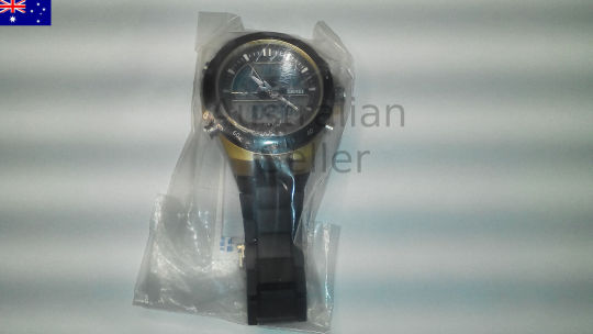
Mechanical Watch 6 hands Automatic 1Pcs
https://www.ebay.com.au/itm/173840921415
Rixtronix Store,electronic components,3D Printer Parts and electronic modules
https://www.ebay.com.au/str/rixtronix
Please donate for buying my children's milk, thanks
http://PayPal.Me/rixtronix
MAX485 SOP8 5Pcs
https://www.ebay.com.au/itm/173840921384
Tapped Spacer M3x25 5Pcs
https://www.ebay.com.au/itm/173841750164
STM32L011 Nucleo 32
https://www.ebay.com.au/itm/173846014737
3D Printed Look Keo Cleat Thicker Hook Areas 1pair, I've tested for more than 1 year ride
https://www.ebay.com.au/itm/173910460603
Female to Female jumper wire 40 Pins 1 Pc
https://www.ebay.com.au/itm/174157283872
Rixtronix LAB is looking for local engineering bussiness partner, please contact us, thanks
Rixtronix LAB 正在寻找当地工程业务合作伙伴,请与我们联系,谢谢
Rixtronix LAB Log
https://rixtronixlab.blogspot.com/
https://rixtronix.joomla.com/
https://bianchi77.wordpress.com/
==================
Offer :

2W Power Resistor With Various Value 22R-1M, 5Pcs Per Lot

High Voltage Mylar Capacitor With Various Value 100pnF-22nF, 5Pcs Per Lot 1-3Kv

Power Amplifier Transistor Toshiba C5198 140V 10A

Molex Connector Male 5 Pcs, Various Model from 2 to 5 pins

Grinder Stone With Various Shape 1Pcs

Power Amplifier Transistor Toshiba A1941 140V 10A

Packaging Bubble Padded Plastic Bag Various Size , 5Pcs Per Lot

SMD Power Diode With Various Value M1,M2,etc 10Pcs Per Lot

Resistor 1/2 W 1% With Various Value 20R-1M, 10Pcs Per Lot

HDMI Connector 2Pcs
Offer :

74HC595 5Pcs

MT8870DE DIP18 4Pcs

TCRT5000 IR Sensor 2Pcs

AMS1117 3.3V 5Pcs

Alkaline Battery AG13 357A CX44 LR44W 10Pcs

DS18B20 5Pcs sensor

MAX232CPE DIP16 2Pcs

74LS04 DIP14 5Pcs

ESD Plastic Bag 200x100mm 10Pcs

Solid Cap 820uF 2.5V 5Pcs
Buy local, helps Australian grows,
Offer :

MicroUSB Connector 5Pcs

LM324 Dual Op Amp 5Pcs

Presta Valve Adaptor For Road Bike 2Pcs

Wifi Adapter RTL8188EUS 1Pcs

MicroSD Connector 5Pcs

Electrolityc 4700uF 25V 5Pcs

22pF 500V SMD 5Pcs Hi-Q

10R SMD 3216 10Pcs

47nF 100V SMD 5Pcs 1812

Through Hole Resistor 0.22 Ohm 2W 10 Pieces
=========================================
Other items to offer :
Buy local , helps Australian grows

DS3231 RTC Module 1Pc

4N60 High Voltage N-FET 4A 600V 2Pcs

Intel Chipset i82801EB 1Pcs

Mini Amplifier Module 1Pcs

C5763 NPN HV Transistor 2pcs

FAST Recovery Diode FR107 10PCS

FAST Recovery Diode FR302 10PCS

HER508 FAST Recovery Diode 5A 1000V 5Pcs

LM2596 TO220 5Pcs

2.2uF 400V High Voltage Capacitor 5Pcs

5Pcs TL431 T0-92 Regulator Chip

IRFS730B N-FET High Voltage 400V 5.5A 2Pcs

LM2596-ADJ 3A TO-263 2Pcs

Atmega128A 64Pins QFP 2Pcs

MAX485 SOP8 5Pcs

M3x15 Polycarbonate Bolt Phillips 10Pcs

Humidity Sensor 5Pcs

M4x20 Bolt Pan Pozi 10Pcs

74HC573 Octal D-type transparent latch 5Pcs
M8 Nylon Nut 4Pcs
=========================================
Other items to offer :
Buy local , helps Australian grows
Offer : Offer :
74HC595 5Pcs
MT8870DE DIP18 4Pcs
TCRT5000 IR Sensor 2Pcs
AMS1117 3.3V 5Pcs
Alkaline Battery AG13 357A CX44 LR44W 10Pcs
DS18B20 5Pcs sensor
MAX232CPE DIP16 2Pcs
74LS04 DIP14 5Pcs
ESD Plastic Bag 200x100mm 10Pcs
Solid Cap 820uF 2.5V 5Pcs

ATMEL 24C08 DIP8 5Pcs
Serial EEPROM 8K I2C

ATMEL 24C16 DIP8 5Pcs
Serial EEPROM 16K I2C

ATMEL 24C32 DIP8 5Pcs
Serial EEPROM 32K I2C

SOP14 to DIP Adapter
Double Side 1.27 and 0.65mm 1pcs

SOP16 to DIP Adapter
Double Side 1.27 and 0.65mm 1pcs

SOT23 and SOP 10 to DIP Adapter
10 pins 0.95 0.5 mm 1pcs

SSOP20 to DIP Adapter Double Side
1.27 and 0.65mm 1pcs

SSOP24 to DIP Adapter Double Side
1.27 and 0.65mm 1pcs

SSOP8 to DIP Adapter Double Side
1.27 and 0.65mm 1pcs

SSOP28 to DIP Adapter Double Side
1.27 and 0.65mm 1pcs
=========================================
Other items to offer :
Buy local , helps Australian grows

24C16 DIP8 9Pcs Flash Memory Chip

AMS1117 1.2V 5Pcs Regulator Chip

RGB LED Crystal Clear 10Pcs

TS2937 CP33 3.3V Regulator 5 Pcs

LM2596 ADJ Regulator SMD 5Pcs

LD1117S33TR 1.3A 3.3V 5Pcs
MAX3232 SMD 5Pcs

MAX232 SMD 5Pcs

Female Spade Crimp 4.8mm Blue 5Pcs

Female Spade Crimp 4.8mm Red 5Pcs

Shunt Pin Header Black 10Pcs

Hall Sensor 3Pins Code 3144 234 2Pcs

PCI Card Riser with Flexibe Ribbon 1Pc

MAX485 DIP8 5Pcs

Fuse 20mmx5mm 3A 5Pcs

Arduino Mega 2560 Brand NEW 1Pc
Green LED Crystal Clear

Combo 3in1 Card Reader 1Pcs

M3 Polycarbonate Nut 10Pcs

Nylon Untapped Spacer M3x20 10Pcs
=========================================
Other items to offer :
Buy local , helps Australian grows

High Voltage Capacitor 560uF 450V 1Pc

Polypropylene Safety Capacitor Various Value 1nF-470nF, 5Pcs Per Lot

3D Printer Heat BlockSet 1Pc

UC3842AN 5 Pcs

Nylon Spacer M3x15 10Pcs

LCD 16x2 Parallel to I2C 1Pc

GPS Antenna Connector SMD 2Pcs

CR2032 Battery 5Pcs

M3x16 Socket Head Stainless Screw 10Pcs

8m 3D Printer Filament PLA Blue

10m 3D Printer Filament ABS Brown Gold

3D Printer NTC 100K with Wire and Connector 1Pc

3D Printer Nozzle tube with teflon 1Pc

NTC 100K for 3D Printer 2Pcs

DIP switch 3pins 5Pcs

Sticker Gold Color 0-9 1Pc

Nylon Tapped Spacer M3x25 10Pcs

3D Printed Nema23 Stand 1Pc

3D Printed Look Keo Cleat Thicker Hook Areas 1pair

High voltage capacitor for switching PSU 6.8uF400V 5pcs
=========================================
Other items to offer :
Buy local , helps Australian grows

STM32L011 Nucleo 32 Dev Board
HER508 FAST Recovery Diode 5A 1000V 5Pcs

ATMEL 89S52 Microcontroller 2Pcs

ATMEGA128A Development Board SMD to DIP adapter 1Pc
4N60 High Voltage N-FET 4A 600V 2Pcs
FAST Recovery Diode FR302 10PCS
Analog and digital quartz sport watch dual time 1Pcs
C5763 NPN HV Transistor 2Pcs

Short SDcard connector 2Pcs
IRFS730B N-FET High Voltage 400V 5.5A 2Pcs
Intel Chipset i82801EB 1Pc

FAST Recovery Diode SR240 10PCS
Mini Amplifier Module 1Pcs

Solenoid Valve 12V 1Pc
FAST Recovery Diode FR107 10PCS

Stereo Connector 2 Pcs

Nylon Spacer M3x15 5Pcs

Capacitor 6800uF 35V 1Pc Low ESR

Capacitor 1uF 450V 5% For Fan

3D Printed Coupler 5mm to 8mm 1Pc
Bike siren Bill Of Materials
CommentDescriptionDesignatorFootprintLibRefQuantityBattery BAT19V Battery 3DBattery1100nF 250VDC C1, C4100nF 250VDC100nF 250VDC2100uF 16V C2, C3Capacitor 100uF 16V100uF 16V2LED 5mm Bright RED D1, D2, D3, D4LED 5mm REDLED 5mm Bright4C9014 NPN TO-92 Q1, Q2, Q3, Q4C9014 TO-92C9014 NPN4C9015 Q5C9015 TO-92C90151470R 0.25W R1, R2Resistor 470 Ohm 0.25WResistor 470 Ohm 0.25W2100K 0.25W 1% R3, R4R 100K 0.25W 1%R 100K 0.25W 1%210K 0.25W R5, R6Resistor 10K 0.25WResistor 10K 0.25W23K9 Blue 1% 0.25W R7, R8R 3K9 0.25 1%R 3K9 0.25W Blue2Speaker SP1SpeakerSpeaker1
0 notes
Text
TP4056 1A Li-ion lithium Battery Charging Module Charging Board Charger TP 4056 - Mini USB
New Post has been published on https://apzweb.com/tp4056-1a-li-ion-lithium-battery-charging-module-charging-board-charger-tp-4056-mini-usb/
TP4056 1A Li-ion lithium Battery Charging Module Charging Board Charger TP 4056 - Mini USB


Price:
(as of Jan 01,1970 00:00:00 UTC – Details)

TP4056 1A Li-ion lithium Battery Charging Module Charging Board Charger TP 4056 In the product image there are 2 similar items joint together, there will be only one item sold in this listing. Power: Medium Power Brand Name: TP4056 Usage: Zener Diode Structure: PNP Special Function: Common Point Contact Diode Frequency: High Frequency Type: Power Module Construction: Planar Type Material: Silicon Install Style: SMD Function: Power Triode Model Number: TP4056.
Onboard MINI USB head can directly link computer USB port charging
The charging board can also be powered by pin (IN + and IN-)
Reserved the TEMP pin header, and can be used as a lithium battery temperature detection PCB board size: 3.73 (cm) x1.5 (cm)/1.46”X0.59”
Input voltage: 4V-8V maximum output charging current: 1000mA
0 notes
Last Seen Blogs

y-ugioh
looks like you're going to the shadow realm

meadow-of-the-linden-tree
Meadow of the Linden Tree


snapadore
Snap Journal

jsabaddict
JSABAddict