#raspberry pi relay
Explore tagged Tumblr posts
Visit Tumblr Blog
Explore Tumblr blogs with no restrictions, modern design and the best experience.
Last Seen Tumblr Blogs


Fun Fact
In 2020, Tumblr had 29.4 million users in the US.
Text
Top 10 Projects for BE Electrical Engineering Students
Embarking on a Bachelor of Engineering (BE) in Electrical Engineering opens up a world of innovation and creativity. One of the best ways to apply theoretical knowledge is through practical projects that not only enhance your skills but also boost your resume. Here are the top 10 projects for BE Electrical Engineering students, designed to challenge you and showcase your talents.
1. Smart Home Automation System
Overview: Develop a system that allows users to control home appliances remotely using a smartphone app or voice commands.
Key Components:
Microcontroller (Arduino or Raspberry Pi)
Wi-Fi or Bluetooth module
Sensors (temperature, motion, light)
Learning Outcome: Understand IoT concepts and the integration of hardware and software.
2. Solar Power Generation System
Overview: Create a solar panel system that converts sunlight into electricity, suitable for powering small devices or homes.
Key Components:
Solar panels
Charge controller
Inverter
Battery storage
Learning Outcome: Gain insights into renewable energy sources and energy conversion.
3. Automated Irrigation System
Overview: Design a system that automates the watering of plants based on soil moisture levels.
Key Components:
Soil moisture sensor
Water pump
Microcontroller
Relay module
Learning Outcome: Learn about sensor integration and automation in agriculture.
4. Electric Vehicle Charging Station
Overview: Build a prototype for an electric vehicle (EV) charging station that monitors and controls charging processes.
Key Components:
Power electronics (rectifier, inverter)
Microcontroller
LCD display
Safety features (fuses, circuit breakers)
Learning Outcome: Explore the fundamentals of electric vehicles and charging technologies.
5. Gesture-Controlled Robot
Overview: Develop a robot that can be controlled using hand gestures via sensors or cameras.
Key Components:
Microcontroller (Arduino)
Motors and wheels
Ultrasonic or infrared sensors
Gesture recognition module
Learning Outcome: Understand robotics, programming, and sensor technologies.
6. Power Factor Correction System
Overview: Create a system that improves the power factor in electrical circuits to enhance efficiency.
Key Components:
Capacitors
Microcontroller
Current and voltage sensors
Relay for switching
Learning Outcome: Learn about power quality and its importance in electrical systems.
7. Wireless Power Transmission
Overview: Experiment with transmitting power wirelessly over short distances.
Key Components:
Resonant inductive coupling setup
Power source
Load (LED, small motor)
Learning Outcome: Explore concepts of electromagnetic fields and energy transfer.
8. Voice-Controlled Home Assistant
Overview: Build a home assistant that can respond to voice commands to control devices or provide information.
Key Components:
Microcontroller (Raspberry Pi preferred)
Voice recognition module
Wi-Fi module
Connected devices (lights, speakers)
Learning Outcome: Gain experience in natural language processing and AI integration.
9. Traffic Light Control System Using Microcontroller
Overview: Design a smart traffic light system that optimizes traffic flow based on real-time data.
Key Components:
Microcontroller (Arduino)
LED lights
Sensors (for vehicle detection)
Timer module
Learning Outcome: Understand traffic management systems and embedded programming.
10. Data Acquisition System
Overview: Develop a system that collects and analyzes data from various sensors (temperature, humidity, etc.).
Key Components:
Microcontroller (Arduino or Raspberry Pi)
Multiple sensors
Data logging software
Display (LCD or web interface)
Learning Outcome: Learn about data collection, processing, and analysis.
Conclusion
Engaging in these projects not only enhances your practical skills but also reinforces your theoretical knowledge. Whether you aim to develop sustainable technologies, innovate in robotics, or contribute to smart cities, these projects can serve as stepping stones in your journey as an electrical engineer. Choose a project that aligns with your interests, and don’t hesitate to seek guidance from your professors and peers. Happy engineering!
5 notes
·
View notes
Text
Relay operated power button

What you need:
a 5V relay module
Raspberry Pi
a bunch of cables
Explanation:
A power button on a computer case lets electricity flow between two power pins upon it being pressed, which is when the motherboard detects the button is pressed and reacts accordingly.

A relay is a specific kind of switch which lets electricity flow conditionally upon the flow of electricity in another circuit. The voltages involved both in motherboard power pins and on Raspberry Pi are generally low to not damage both, but we're taking extra precautions to electrically separate them both.
"5V relay module" here means that 5V is the voltage that is required for the relay module to work, while the controlling voltage can be lower. It being relay module it means it also has a flyback diode we'd otherwise have to provide ourselves.

Raspberry Pi's GPIO pins are programmable and can be controlled through Python code, and operate on 3.3V. Raspberry Pi also provides 5V output, but this one is not controllable.
By
connecting a power button to rPi GPIO pins
connecting the 5V voltage output pin from rPi to the relay module's Vcc input pin
connecting the ground pin from rPi to the relay module's groud pin
connecting programmable GPIO pins as the relay module's input pin
connecting the relay module's outputs (the normally open one and the ground) to the motherboard power pins
running some code on rPi
We can extend the power button functionality so Raspberry Pi can turn on and off our computer, while also still keeping the power button working.
Which is what I use to remotely turn on my computer on, by SSHing to rPi and running a script to turn the PC on while I'm away from home.
Why not Wake-On-LAN?
Wake-On-LAN has restrictions which makes it not as reliable as it could be, for example:
The ability to wake from a hybrid shutdown state (S4) (aka Fast Startup) or a soft powered-off state (S5) is unsupported in Windows 8 and above
The code and explanation for it in Part 2, when I get to writing it.
17 notes
·
View notes
Text
This 16 Channel Relay Module consists of sixteen 5V relays and each one of the individual relay needs 15-20mA driver current. This module has a light coupling protection (optocoupler) which provide opto-isolation for safety purposes. This is a Relay module of 16 channel interface board that can be control various appliances, and other electronic equipment with large current. It can be controlled by Micro-controllers like Arduino, Raspberry-pi, ARM, TTL logic directly.
3 notes
·
View notes
Text
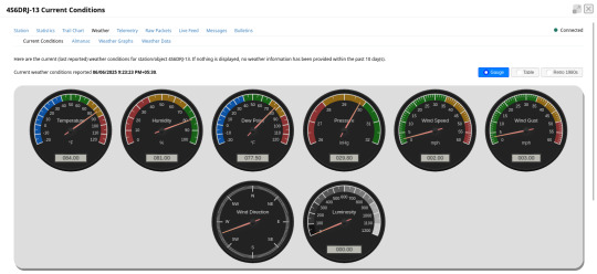
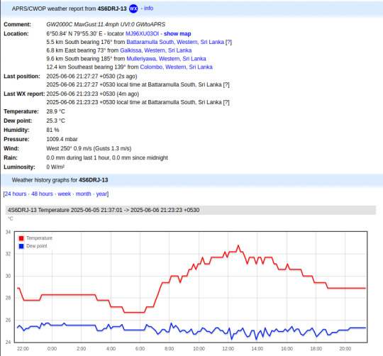
Ecowitt weather station to APRS bridge
Ecowitt2APRS is a new open-source Linux service that I have been working on for the past few weeks. This project is designed to seamlessly integrate weather data from Ecowitt compatible professional weather stations into the global Automatic Packet Reporting System Internet Service (APRS-IS) network, transmitting this information in the standardized format of APRS weather packets.
APRS, an amateur radio-based system, facilitates real-time tactical digital communications, covering applications such as GPS position reporting and the dissemination of meteorological data. Ecowitt2APRS addresses a specific need within this ecosystem: providing a lightweight and efficient method for weather stations to contribute to this data stream.
The Ecowitt2APRS service is developed as a minimalist daemon for Linux environments. It ingests live weather data from Ecowitt compatible stations, converts it into the required APRS weather packet format, and then relays these packets to the APRS-IS network. One of my primary objectives was to create a service that operates effectively on minimal Linux systems, such as low-power SBCs like the Raspberry Pi Zero. This enables dedicated, continuous weather reporting with minimal operational overhead and power consumption.
I'm testing this system with my Ecowitt WiFi weather hub - GW2000C. The live feed from my Ecowitt2APRS instance is available as 4S6DRJ-13, and I am hosting the Ecowitt2APRS daemon on the Orange Pi Zero LTS board.
As an open-source initiative, all source code, documentation, and installation instructions are publicly available in the project repository on GitHub. This page also provides pre-built binaries of Ecowitt2APRS for ARM64, ARMv7, and AMD64 architectures. Anyone interested in deploying this can download the binaries or compile the source code themselves. The source code has limited external dependencies and can be easily built using the GCC toolchain. The compilation steps are outlined in the project's readme file.
To manually deploy the downloaded package, follow these steps:
1. Extract the files:
tar -xvf ./ec-aprs-wx-linux-<PLATFORM>.tar.gz
2. Copy the necessary files:
sudo cp ./ec-aprs-wx /usr/local/bin/ec-aprs-wx sudo cp ./config.cfg /etc/ec-aprs-wx.cfg sudo cp ./ec-aprs-wx.service /etc/systemd/system/ec-aprs-wx.service
Before starting the service, make sure to open the /etc/ec-aprs-wx.cfg file and edit the fields: APRS_CALLSIGN_SSID, APRS_PASSCODE, APRS_LATITUDE, and APRS_LONGITUDE. The details for these fields are covered in the readme file of the project.
To start the service, issue the following command:
sudo systemctl daemon-reload
To enable the service to start automatically on system reboot, issue the following command:
sudo systemctl enable ec-aprs-wx.service
To trigger this service, the Ecowitt device needs to be configured, with the configuration steps detailed in the project's readme file.
If all configuration steps are correct, you should be able to observe the weather data feed from APRS monitoring sites like https://aprs.fi or https://aprs.to.
0 notes
Text
No input mixer + various inputs, jam while testing new synced lighting bits. My drum synth+patterns puredata patch on the raspberry pi is talking to a python script to activate the pi's pins which controls some relay switches to turn some power plugs on and off.
I'll likely have an expanded version of this rig for the gig on 29/05/2025: https://events.humanitix.com/warblin-album-launch
0 notes

Text
The future of smart home control begins with one sleek, powerful interface — the Nextion NX8048P050-011R 5.0” Intelligent Resistive HMI Touchscreen. Ideal for automation projects, this display offers unmatched user experience, intelligent processing, and seamless integration. If you're planning to level up your smart home or automation setup in 2025, this intelligent touchscreen should be on your radar.
Available now at www.sonoff.in, this module is a must-have for developers, hobbyists, and smart home enthusiasts.
Power-Packed 5.0” Intelligent Display for Smart Control
The Nextion NX8048P050-011R boasts a 5.0-inch resistive touchscreen, offering sharp visuals and precise touch response. Designed without an enclosure, this screen gives flexibility in mounting it into custom panels, enclosures, or control stations.
The resistive touch feature supports usage even when wearing gloves — making it practical for industrial, automation, and DIY applications. It’s a display that adapts to your environment, not the other way around.
Advanced HMI Capabilities Built for Efficiency
This is more than just a screen. It's a powerful HMI (Human Machine Interface) equipped with:
Onboard microcontroller for fast UI rendering
Rich GUI design with Nextion Editor
Easy drag-and-drop interface development
Support for static images, buttons, sliders, and dynamic text
Integrated flash memory for storing UI pages
You can build multi-layered smart interfaces without relying on external MCUs for rendering. Control everything from HVAC to lighting systems — with just a touch.
Streamlined Communication with Embedded Systems
The Nextion NX8048P050-011R communicates using UART serial communication, making it compatible with Arduino, Raspberry Pi, ESP32, and more. Developers love how it simplifies hardware-software interaction.
Commands are sent via a simple serial interface, which dramatically reduces processing load on your main MCU. This allows developers to allocate power where it truly matters.
Why It’s Perfect for Home and Industrial Automation
Here’s why the Nextion NX8048P050-011R is a game changer:
Compact but powerful – Fits in tight spaces while delivering advanced UI functionality.
Customizable UI – Create polished, user-friendly interfaces tailored to your smart home design.
Responsive Touch – Reliable performance in both residential and industrial settings.
Highly Compatible – Works seamlessly with Sonoff smart switches and automation modules from www.sonoff.in.
Whether you’re managing lighting, thermostats, or entire smart systems, this touchscreen gives you intuitive and elegant control.
Nextion Editor – No Code? No Problem.
The Nextion Editor software is a dream for non-programmers. You don’t need advanced coding skills to build dynamic user interfaces. Just drag and drop components onto your screen canvas.
From progress bars to image sliders, your interface can be as simple or complex as your imagination allows. With built-in event triggers, automation becomes a breeze.
Technical Specs at a Glance
Let’s dive into the core specs that make this touchscreen a powerhouse:
Display Size: 5.0” resistive touch panel
Resolution: 800x480 pixels
Flash Memory: 16MB
RAM: 3584 bytes
EEPROM: 1024 bytes
MCU: 48MHz
Serial Port: TTL UART
Operating Voltage: 5V
These specifications ensure smooth performance, fast response, and consistent reliability in demanding automation environments.
Installation and Custom Integration
Thanks to its open-frame design, you can install the NX8048P050-011R in custom enclosures or panels. Whether it’s a wall-mounted control panel or embedded into a furniture piece, the flexibility is unbeatable.
Pair it with Sonoff Wi-Fi switches or smart relays to create a smart home interface that looks and feels professional.
Smart Solutions, Smarter Shopping with www.sonoff.in
Looking for a reliable supplier in India? www.sonoff.in is the trusted destination for Nextion displays, Sonoff smart devices, and complete home automation solutions.
They offer fast delivery, excellent customer service, and authentic products backed by warranty. Get access to India’s top smart home gadgets — all in one place.
Conclusion: Smart Control Starts Here
The Nextion NX8048P050-011R 5.0” intelligent touchscreen is the perfect HMI solution for next-gen smart home setups. Its seamless performance, rich feature set, and compatibility with Sonoff devices from www.sonoff.in make it a standout choice.
Don't settle for clunky switches and outdated interfaces. Take control of your environment — the smart way.
Explore the future of home automation at www.sonoff.in and power up your smart living journey today.
#sonoff#smarthome#smartappliances#googlehomeintegration#alexacompatible#sonoffpowr3#homeautomation#sonoffindia#wifismartswitch
0 notes
Text
Shelly Plus #4: PIR Sensor am AddOn

In diesem Beitrag möchte ich dir zeigen, wie du einen PIR Sensor an das Shelly Plus AddOn anschließt und das Signal zur Steuerung des Relais verwenden kannst.

Shelly Plus #4: PIR Sensor am AddOn Es gibt mit dem Shelly Motion 2 bereits eine fertige Lösung. Jedoch ist diese für mich viel zu langweilig und daher möchte ich diese Schaltung selber aufbauen und dir hier präsentieren. An das Shelly Plus AddOn kannst du viele Sensoren anschließen und auswerten, welche für Arduino & Raspberry Pi gedacht sind. Diese sind teilweise nicht so hochwertig und auch manchmal sehr kurzlebig, aber zum ein wenig Herumspielen sind diese voll okay.

Das Shelly Plus AddOn habe ich dir bereits in den nachfolgenden Beiträgen vorgestellt: - Shelly Plus #2: Shelly Plus AddOn - Shelly Plus #3: Regensensor am AddOn
Benötigte Ressourcen für dieses Projekt
Wenn du dieses kleine Beispiel nachbauen möchtest, dann benötigst du: - einen Shelly Plus 1*, - ein Shelly Plus AddOn*, - einen PIR Sensor*, - drei Breadboardkabel*, männlich-weiblich, 20 cm - eine Zuleitung für den Shelly Plus 1** Hinweis von mir: Die mit einem Sternchen (*) markierten Links sind Affiliate-Links. Wenn du über diese Links einkaufst, erhalte ich eine kleine Provision, die dazu beiträgt, diesen Blog zu unterstützen. Der Preis für dich bleibt dabei unverändert. Vielen Dank für deine Unterstützung! ** Die Zuleitung für den Shelly bekommst du im örtlichen Baumarkt als Meterware und ebenso einen passenden Stecker. Ich empfehle dir noch zusätzlich 3 Aderendhülsen aufzusetzen, damit die feinen Adern von den Schraubklemmen nicht zerquetscht werden.
Aufbau der Schaltung
Durch den Shelly AddOn ist der Aufbau der Schaltung recht easy, denn dieser ist auf dem Gehäuse sehr gut beschrieben.


Den PIR Sensor gibt es in (mir bisher bekannten) zwei Varianten, beiden ist jedoch gleich das diese über 5 V betrieben werden und einen digitalen Ausgang haben.

PIR Sensoren im Vergleich Ich verwende in diesem Beitrag den PIR Sensor HC-SR501*. Dieser Sensor verfügt über zwei kleine Drehpotentiometer, an welchen man die Empfindlichkeit regeln kann.


Anschluss des PIR Sensors an das Shelly Plus AddOn
Wie erwähnt und auf den Bildern zu sehen besitzt der PIR Sensor 3 Pins, VCC, OUT& GND. Welche wie folgt an das Shelly Plus AddOn angeschlossen werden.

PIR Sensor HC-SR501 am Shelly Plus AddOn Im nachfolgenden YouTube-Video zeige ich dir kurz, wie du diesen anschließen und in der Shelly App einrichten kannst. https://youtu.be/yO2VfprW0N4 Im letzten Beitrag zum Regensensor Modul habe ich bereits zwei Szenen erstellt, welche mit einem digitalen Signal 0/1 oder HIGH/LOW arbeitet und somit für diesen Beitrag wiederverwendet werden können. Wenn wir eine Lampe damit steuern möchten, können wir zusätzlich noch eine Verzögerung einbauen, sodass wir zum Verlassen des Bereiches noch etwas mehr Licht & Zeit haben. Read the full article
0 notes
Text
5V Single Channel Relay Module: A Detailed Guide
The 5V Single Channel Relay Module is a powerful and compact device that serves as a bridge between low-power circuits and high-power devices. It is commonly used in projects requiring electrical isolation or automation, making it popular among hobbyists and engineers alike. In this guide, we will explore its functions, applications, wiring, and much more to give you a full understanding of this versatile module.
What is a 5V Single Channel Relay Module?
A 5V Single Channel Relay Module is an electronic switching device designed to control high-voltage electrical devices using a low-power input. The term "5V" refers to the operating voltage required to activate the relay, while "single channel" means it can control one device or circuit at a time.
The module is widely used in home automation, robotics, and various DIY projects. Its ability to switch between circuits without a direct electrical connection makes it a safer choice for controlling high-voltage appliances.
How Does a 5V Single Channel Relay Module Work?
The relay module operates as an electromechanical switch. It uses a small input voltage to energize an internal coil, creating a magnetic field. This magnetic field moves a lever inside the relay to either open or close a circuit. By doing so, it allows or interrupts the flow of current to the connected device.
The module typically has three main connections:
Input Pins: For connecting the control signal.
Common Pin (COM): The shared connection between the relay and the device.
Normally Open (NO) and Normally Closed (NC): These determine the state of the circuit (open or closed) when the relay is activated or deactivated.
Features of a 5V Single Channel Relay Module
Low Power Requirement: Operates on just 5V input.
Isolation: Electrical isolation ensures safety between low-voltage control circuits and high-voltage devices.
LED Indicators: Built-in LEDs indicate the relay’s state, making it easy to troubleshoot.
Compact Design: Small and lightweight, suitable for various projects.
Applications of the 5V Single Channel Relay Module
The 5V Single Channel Relay Module has countless uses in modern electronics, such as:
Home Automation: Control appliances like lights, fans, or water pumps using microcontrollers or development boards like Arduino or Raspberry Pi.
Robotics: Enable remote or automated control of motors and actuators.
Industrial Automation: Automate machinery and monitor processes.
Smart IoT Systems: Integrate with IoT platforms to create smart, connected systems.
How to Wire a 5V Single Channel Relay Module
Connecting a 5V Single Channel Relay Module to a microcontroller is straightforward. Follow these steps for basic wiring:
Power the Module: Connect the VCC pin to the 5V output of your microcontroller or external power supply.
Connect the Ground: Link the GND pin of the relay to the ground pin of your controller.
Signal Pin: Attach the IN pin to the microcontroller's GPIO pin that will control the relay.
Device Connection: Wire the high-voltage device to the NO, NC, and COM pins based on your requirements.
Always ensure proper insulation and avoid direct contact with live wires during setup.
Benefits of Using a 5V Single Channel Relay Module
Safety: Provides electrical isolation, protecting the low-power circuit.
Versatility: Works with a range of devices and voltages.
Reliability: Durable and can withstand frequent switching operations.
How to Test a 5V Single Channel Relay Module
To test the module, follow these simple steps:
Power Up the Relay: Connect the module to a 5V power source.
Apply Control Signal: Send a HIGH or LOW signal to the input pin.
Listen for a Click: A clicking sound indicates the relay is switching states.
Check the LED Indicator: Ensure the LED lights up when activated.
Testing ensures the module functions as intended before integrating it into your project.
Choosing the Right Relay Module
When selecting a relay module, consider the following factors:
Operating Voltage: Ensure compatibility with your controller.
Load Capacity: Check the maximum current and voltage the relay can handle.
Channels: Choose a module with an appropriate number of channels based on your needs.
Integrating the 5V Single Channel Relay Module with Arduino
One of the most popular applications of this module is in Arduino projects. Here’s a simple example:
Components Required
Arduino Board
5V Single Channel Relay Module
Jumper Wires
Load (e.g., a light bulb)
Steps
Connect the relay module's VCC and GND to the Arduino’s 5V and GND pins.
Attach the IN pin to a digital GPIO pin (e.g., pin 7).
Write a program to toggle the relay using Arduino’s digitalWrite function.
Upload the code and observe the relay switching the connected load.
Maintenance and Troubleshooting
Regular maintenance can extend the lifespan of your 5V Single Channel Relay Module. Check for the following:
Loose Connections: Ensure all wires are securely connected.
Dust and Debris: Clean the module periodically to prevent short circuits.
Wear and Tear: Inspect for physical damage or corrosion.
If the module fails to function, verify the power supply and input signals. Replace damaged modules promptly to avoid system downtime.
0 notes
Text
DIY Voice-Controlled Smart Home System Using Cloudtopiaa
Introduction
Imagine walking into your home and simply saying, “Turn on the lights,” and the lights switch on automatically! In this guide, we’ll show you how to build a Voice-Controlled Smart Home System to control lights, fans, and other devices using voice commands. By leveraging Cloudtopiaa as your cloud platform, you’ll have a secure and reliable space to handle device communication and data storage. This project uses a microcontroller to manage home appliances, integrates with Google Assistant or Amazon Alexa via IFTTT, and is expandable for future enhancements.
Why Build a Voice-Controlled Smart Home System with Cloudtopiaa?
Voice-controlled home automation makes life more convenient, saves energy, and provides easy accessibility. With Cloudtopiaa, you gain hands-on experience with IoT integration, MQTT, and networked appliance control in a reliable cloud environment. Cloudtopiaa’s managed cloud services ensure your data is secure, scalable, and accessible wherever you are.
Key Benefits of a Voice-Controlled Smart Home System
Convenience: Control appliances effortlessly with voice commands.
Energy Efficiency: Reduce energy consumption by remotely managing devices.
Accessibility: Beneficial for people with mobility or accessibility needs.
Reliability with Cloudtopiaa: Cloudtopiaa’s scalable cloud services give you a secure, consistent, and professional-grade backend for your smart home project.
Key Components and Technologies
To build your Voice-Controlled Smart Home System, you will need:
Microcontroller:
ESP8266: Compact and ideal for control tasks with Wi-Fi capabilities.
Raspberry Pi: Optional for more advanced setups requiring local processing.
Relay Module:
Use a relay module to control appliances safely. Each relay channel can be configured to switch on or off a device.
Voice Assistant Integration (IFTTT):
Use IFTTT (If This Then That) to connect your devices with Google Assistant or Amazon Alexa. IFTTT enables custom voice commands that Cloudtopiaa then manages through MQTT.
2. MQTT Protocol (via Cloudtopiaa):
MQTT acts as a real-time communication protocol to connect your devices. By hosting your MQTT broker on Cloudtopiaa, you gain secure, managed cloud connectivity to support voice commands and responses.
Additional Components:
Jumper wires and breadboard for connections.
Power supply for ESP8266 or Raspberry Pi.
Light bulbs, fan, or other devices you want to control.
Step-by-Step Guide
Step 1: Setting Up the Microcontroller
Prepare Your Microcontroller:
For this guide, we’ll use the ESP8266 with built-in Wi-Fi, ideal for integration with Cloudtopiaa.
Connect the Relays:
Connect the ESP8266’s GPIO pins to the relay module. Each relay will control a separate appliance, such as a light or fan.
Power the relay module safely and connect it to your microcontroller for reliable control.
Step 2: Set Up MQTT on Cloudtopiaa for Communication
Create an MQTT Broker on Cloudtopiaa:
Deploy an MQTT broker in Cloudtopiaa to manage communication between your devices and the voice assistants. Cloudtopiaa’s managed services provide a stable, secure environment to host this broker.
Configure the ESP8266 to Connect to Cloudtopiaa’s MQTT Broker:
Install MQTT libraries on the ESP8266 and configure it to subscribe to MQTT topics for each appliance.
Here’s a basic code example for ESP8266:import network import time from machine import Pin from umqtt.simple import MQTTClient
# Wi-Fi and MQTT setup WIFI_SSID = "your_wifi_ssid" WIFI_PASSWORD = "your_wifi_password" MQTT_BROKER = "your_cloudtopiaa_mqtt_broker_address" CLIENT_ID = "ESP8266Client" LIGHT_TOPIC = "home/livingroom/light" FAN_TOPIC = "home/livingroom/fan"
# GPIO setup light = Pin(2, Pin.OUT) fan = Pin(4, Pin.OUT)
def connect_wifi(): wifi = network.WLAN(network.STA_IF) wifi.active(True) wifi.connect(WIFI_SSID, WIFI_PASSWORD) while not wifi.isconnected(): time.sleep(1) print("Connected to Wi-Fi")
def mqtt_callback(topic, msg): if topic == LIGHT_TOPIC: light.value(1 if msg == b'ON' else 0) elif topic == FAN_TOPIC: fan.value(1 if msg == b'ON' else 0)
# Main program connect_wifi() client = MQTTClient(CLIENT_ID, MQTT_BROKER) client.set_callback(mqtt_callback) client.connect() client.subscribe(LIGHT_TOPIC) client.subscribe(FAN_TOPIC)
while True: client.wait_msg()
Step 3: Integrate with Google Assistant or Alexa Using IFTTT
Create an IFTTT Account: Sign up at IFTTT.com and set up the Google Assistant or Alexa integration.
Create Applets for Each Command:
Set up IFTTT applets with Google Assistant or Alexa for each appliance command.
Configure the Webhooks Service:
Use IFTTT’s Webhooks service to send HTTP requests to the MQTT broker on Cloudtopiaa, issuing commands to turn devices on or off.
Step 4: Write IFTTT Webhook Commands for Cloudtopiaa
Each IFTTT webhook command sends an HTTP request to your MQTT broker, publishing messages to the correct topics on Cloudtopiaa.
Here’s an example setup:{ "method": "POST", "url": "https://your_cloudtopiaa_mqtt_broker_address/api/publish", "body": { "topic": "home/livingroom/light", "message": "ON" } }
Step 5: Test Your System
Connect Appliances: Attach your appliances (lights, fans) to the relay module.
Test Voice Commands: Try commands like “Turn on the light,” and verify if the devices respond correctly.
Check MQTT Messaging on Cloudtopiaa: Verify that each device accurately follows MQTT messages sent via IFTTT.
Additional Ideas and Expansions
. Add More Devices: Expand your setup by adding more MQTT topics and relays for additional appliances.
Automation Routines: Create IFTTT routines that automate actions based on environmental factors or time of day.
Custom Dashboards: Use Cloudtopiaa’s data visualization capabilities to create a real-time dashboard for monitoring and controlling devices.
Local Backup: For additional control, consider hosting a Raspberry Pi MQTT broker as a backup, allowing local device control if necessary.
Conclusion
Congratulations! You’ve built a Voice-Controlled Smart Home System with Cloudtopiaa, giving you convenient, cloud-backed control of your home appliances. By leveraging Cloudtopiaa’s secure infrastructure, you gain scalable, reliable connectivity for your IoT project. Plus, you can continue expanding this setup with more devices, dashboards, and automations for a fully customized smart home.
Additional Resources
Cloudtopiaa Documentation
IFTTT Documentation
ESP8266 MQTT Tutorial
This system showcases how Cloudtopiaa’s cloud services bring security, scalability, and professional-grade reliability to a DIY project — turning your house into a fully controlled, voice-activated smart home.
#tech4bizsolutions #SmartHomeDIY #VoiceControlledHome #Cloudtopiaa #SmartHomeTech #DIYHomeAutomation #VoiceAssistant #HomeAutomation #TechForHome #SmartLiving #DIYTech
0 notes
Text
10 Exciting RP2040 Project Ideas
The Raspberry Pi Pico, powered by the RP2040 microcontroller, has taken the maker community by storm with its affordability and versatility. If you're looking for some exciting project ideas to try with your RP2040, you're in the right place! In this article, we'll explore 10 innovative projects that showcase the capabilities of the RP2040 and inspire your next creation.
Introduction
The RP2040 is a powerful microcontroller that can be used in a wide range of projects, from simple LED blinkers to complex IoT devices. Its dual-core ARM Cortex-M0+ processor and generous amount of RAM make it ideal for multitasking and handling various tasks simultaneously. Let's dive into some exciting project ideas to unleash the full potential of the RP2040.
1. Blinking LED
A classic project for beginners, the blinking LED demonstrates the basic functionality of the RP2040. By controlling the GPIO pins, you can make an LED blink at different rates, creating various patterns and effects.
2. Temperature Monitoring System
Use the RP2040's ADC to read temperature values from a sensor and display them on an LCD screen. You can also set up alerts to notify you when the temperature exceeds a certain threshold.
3. Motion-Activated Camera
Create a motion-activated camera using the RP2040 and a camera module. The RP2040 can detect motion using a PIR sensor and trigger the camera to capture images or videos.
4. Smart Weather Station
Build a weather station that collects data such as temperature, humidity, and air pressure using sensors. Display the data on an OLED screen and upload it to a cloud service for remote monitoring.
5. Home Automation System
Control lights, appliances, and other devices in your home using the RP2040 and relays. You can create a mobile app or a web interface to control the system remotely.
6. Game Console Emulator
Turn your RP2040 into a retro game console emulator by installing emulators for classic gaming consoles. Use the GPIO pins to connect controllers and play your favorite games.
7. MIDI Controller
Build a MIDI controller using the RP2040 and potentiometers, buttons, and sliders. Use it to control music software or hardware synthesizers.
8. Internet Radio
Create an internet radio player using the RP2040 and a Wi-Fi module. Stream music from online radio stations and control playback using buttons or a web interface.
9. AI Voice Assistant
Build an AI voice assistant using the RP2040 and a microphone. Use services like Google Assistant or Alexa to control smart devices, play music, and answer questions.
10. Conclusion
The RP2040 opens up a world of possibilities for makers and hobbyists. With its powerful features and affordable price, it's the perfect platform for experimenting with electronics and programming. Whether you're a beginner or an experienced maker, these project ideas will help you get started with the RP2040 and unleash your creativity.
0 notes
Text
This 16 Channel Relay Module consists of sixteen 12V relays and each one of the individual relays needs 15-20mA driver current. This module has coupling protection (optocoupler) which provides opto-isolation for safety purposes. This is a Relay module of 16 channel interface board that can be control various appliances, and other electronic equipment with a large current. It can be controlled by Micro-controllers like Arduino, Raspberry-pi, ARM, TTL logic directly.
2 notes
·
View notes
Text
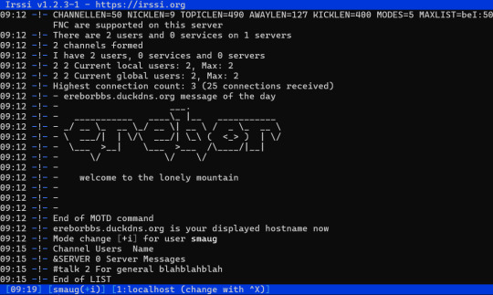
Other distractions: Internet Relay Chat
I have beenfutzing around with my old Raspberry Pi lately, and a lot of my energy went into that. That and talking on the usenet. My main project actually started out as making a nntp-based forum, but on the way I got distracted by all those other shiny terminal apps that I met along the way. Well, I say shiny. I mean, they are CLI apps. I am just interested in some of those older kinds of…
View On WordPress
0 notes
Video
youtube
AUTOMATIC IRRIGATION SOIL MOISTURE CONTENT CONTROL | Auto Irrigation using Soil Moisture Sensing | Automatic Irrigation System Using Soil Moisture Sensor | Smart Irrigation Technology Controllers and Sensors | plant watering system with new blynk update | plant watering system | plant watering system using nodemcu and blynk | plant watering system using iot | smart irrigation system | smart plant watering system.***********************************************************If You Want To Purchase the Full Working Project KITMail Us: [email protected] Name Along With You-Tube Video LinkWe are Located at Telangana, Hyderabad, Boduppal. Project Changes also Made according to Student Requirementshttp://svsembedded.com/ https://www.svskits.in/ http://svsembedded.in/ http://www.svskit.com/M1: 91 9491535690 M2: 91 7842358459 We Will Send Working Model Project KIT through DTDC / DHL / Blue Dart / First Flight Courier ServiceWe Will Provide Project Soft Data through Google Drive1. Project Abstract / Synopsis 2. Project Related Datasheets of Each Component3. Project Sample Report / Documentation4. Project Kit Circuit / Schematic Diagram 5. Project Kit Working Software Code6. Project Related Software Compilers7. Project Related Sample PPT’s8. Project Kit Photos9. Project Kit Working Video linksLatest Projects with Year Wise YouTube video Links157 Projects https://svsembedded.com/ieee_2022.php135 Projects https://svsembedded.com/ieee_2021.php 151 Projects https://svsembedded.com/ieee_2020.php103 Projects https://svsembedded.com/ieee_2019.php61 Projects https://svsembedded.com/ieee_2018.php171 Projects https://svsembedded.com/ieee_2017.php170 Projects https://svsembedded.com/ieee_2016.php67 Projects https://svsembedded.com/ieee_2015.php55 Projects https://svsembedded.com/ieee_2014.php43 Projects https://svsembedded.com/ieee_2013.php1100 Projects https://www.svskit.com/2022/02/900-pr...***********************************************************1. How to make Automatic Plant Watering System using Arduino UNO and Soil Sensor,2. Water Your Garden with IoT - Soil Moisture Sensors,3. Automatic Irrigation System using Soil Moisture Sensor,4. Smart Irrigation || Automated irrigation process using Arduino Moisture sensor and water pump|| IoT,5. How to make Automatic Irrigation System using Soil sensor,6. Capacitive Soil Moisture Sensors don't work correctly ESP32 Raspberry Pi,7. Soil Moisture Sensor with Arduino Uno,8. Agriculture Projects: AUTOMATIC IRRIGATION WATER SUPPLY MONITORING AND CONTROL SYSTEM,9. Automatic Irrigation System using Soil Moisture Sensor,10. How to make Automatic Agriculture System project | Smart Irrigation System | mini project idea 2023,11. IoT Based Smart Agriculture Automatic Irrigation System with ESP8266,12. Smart Irrigation System | Arduino Uno | DHT11 | Humidity Sensor | Soil Moisture Sensor | Relay,13. Smart Irrigation System | Arduino | Soil Moisture Sensor | Relay | DC Water Pump | Arduino Projects,14. How to build a IOT Smart Irrigation System with Blynk, NodeMCU, and Soil Moisture,15. Auto Irrigation using Soil Moisture Sensing,16. IoT Based Plant Watering System Indoor project using ESP32 Blynk | IoT Projects 2023,17. Automatic Watering System sensors kit | Mini water pump, Battery Case, Soil Moisture Detector Module,18. IRRIGATION WATER SUPPLY MONITORING
0 notes
