#raspberry pi relay light
Explore tagged Tumblr posts
Visit Tumblr Blog
Explore Tumblr blogs with no restrictions, modern design and the best experience.
Last Seen Tumblr Blogs


Fun Fact
In February 2021, Tumblr had 518.6 million blog accounts.
Text
Top 10 Projects for BE Electrical Engineering Students
Embarking on a Bachelor of Engineering (BE) in Electrical Engineering opens up a world of innovation and creativity. One of the best ways to apply theoretical knowledge is through practical projects that not only enhance your skills but also boost your resume. Here are the top 10 projects for BE Electrical Engineering students, designed to challenge you and showcase your talents.
1. Smart Home Automation System
Overview: Develop a system that allows users to control home appliances remotely using a smartphone app or voice commands.
Key Components:
Microcontroller (Arduino or Raspberry Pi)
Wi-Fi or Bluetooth module
Sensors (temperature, motion, light)
Learning Outcome: Understand IoT concepts and the integration of hardware and software.
2. Solar Power Generation System
Overview: Create a solar panel system that converts sunlight into electricity, suitable for powering small devices or homes.
Key Components:
Solar panels
Charge controller
Inverter
Battery storage
Learning Outcome: Gain insights into renewable energy sources and energy conversion.
3. Automated Irrigation System
Overview: Design a system that automates the watering of plants based on soil moisture levels.
Key Components:
Soil moisture sensor
Water pump
Microcontroller
Relay module
Learning Outcome: Learn about sensor integration and automation in agriculture.
4. Electric Vehicle Charging Station
Overview: Build a prototype for an electric vehicle (EV) charging station that monitors and controls charging processes.
Key Components:
Power electronics (rectifier, inverter)
Microcontroller
LCD display
Safety features (fuses, circuit breakers)
Learning Outcome: Explore the fundamentals of electric vehicles and charging technologies.
5. Gesture-Controlled Robot
Overview: Develop a robot that can be controlled using hand gestures via sensors or cameras.
Key Components:
Microcontroller (Arduino)
Motors and wheels
Ultrasonic or infrared sensors
Gesture recognition module
Learning Outcome: Understand robotics, programming, and sensor technologies.
6. Power Factor Correction System
Overview: Create a system that improves the power factor in electrical circuits to enhance efficiency.
Key Components:
Capacitors
Microcontroller
Current and voltage sensors
Relay for switching
Learning Outcome: Learn about power quality and its importance in electrical systems.
7. Wireless Power Transmission
Overview: Experiment with transmitting power wirelessly over short distances.
Key Components:
Resonant inductive coupling setup
Power source
Load (LED, small motor)
Learning Outcome: Explore concepts of electromagnetic fields and energy transfer.
8. Voice-Controlled Home Assistant
Overview: Build a home assistant that can respond to voice commands to control devices or provide information.
Key Components:
Microcontroller (Raspberry Pi preferred)
Voice recognition module
Wi-Fi module
Connected devices (lights, speakers)
Learning Outcome: Gain experience in natural language processing and AI integration.
9. Traffic Light Control System Using Microcontroller
Overview: Design a smart traffic light system that optimizes traffic flow based on real-time data.
Key Components:
Microcontroller (Arduino)
LED lights
Sensors (for vehicle detection)
Timer module
Learning Outcome: Understand traffic management systems and embedded programming.
10. Data Acquisition System
Overview: Develop a system that collects and analyzes data from various sensors (temperature, humidity, etc.).
Key Components:
Microcontroller (Arduino or Raspberry Pi)
Multiple sensors
Data logging software
Display (LCD or web interface)
Learning Outcome: Learn about data collection, processing, and analysis.
Conclusion
Engaging in these projects not only enhances your practical skills but also reinforces your theoretical knowledge. Whether you aim to develop sustainable technologies, innovate in robotics, or contribute to smart cities, these projects can serve as stepping stones in your journey as an electrical engineer. Choose a project that aligns with your interests, and don’t hesitate to seek guidance from your professors and peers. Happy engineering!
5 notes
·
View notes
Text
This 16 Channel Relay Module consists of sixteen 5V relays and each one of the individual relay needs 15-20mA driver current. This module has a light coupling protection (optocoupler) which provide opto-isolation for safety purposes. This is a Relay module of 16 channel interface board that can be control various appliances, and other electronic equipment with large current. It can be controlled by Micro-controllers like Arduino, Raspberry-pi, ARM, TTL logic directly.
3 notes
·
View notes
Text
No input mixer + various inputs, jam while testing new synced lighting bits. My drum synth+patterns puredata patch on the raspberry pi is talking to a python script to activate the pi's pins which controls some relay switches to turn some power plugs on and off.
I'll likely have an expanded version of this rig for the gig on 29/05/2025: https://events.humanitix.com/warblin-album-launch
0 notes
Text
The future of smart home control begins with one sleek, powerful interface — the Nextion NX8048P050-011R 5.0” Intelligent Resistive HMI Touchscreen. Ideal for automation projects, this display offers unmatched user experience, intelligent processing, and seamless integration. If you're planning to level up your smart home or automation setup in 2025, this intelligent touchscreen should be on your radar.
Available now at www.sonoff.in, this module is a must-have for developers, hobbyists, and smart home enthusiasts.
Power-Packed 5.0” Intelligent Display for Smart Control
The Nextion NX8048P050-011R boasts a 5.0-inch resistive touchscreen, offering sharp visuals and precise touch response. Designed without an enclosure, this screen gives flexibility in mounting it into custom panels, enclosures, or control stations.
The resistive touch feature supports usage even when wearing gloves — making it practical for industrial, automation, and DIY applications. It’s a display that adapts to your environment, not the other way around.
Advanced HMI Capabilities Built for Efficiency
This is more than just a screen. It's a powerful HMI (Human Machine Interface) equipped with:
Onboard microcontroller for fast UI rendering
Rich GUI design with Nextion Editor
Easy drag-and-drop interface development
Support for static images, buttons, sliders, and dynamic text
Integrated flash memory for storing UI pages
You can build multi-layered smart interfaces without relying on external MCUs for rendering. Control everything from HVAC to lighting systems — with just a touch.
Streamlined Communication with Embedded Systems
The Nextion NX8048P050-011R communicates using UART serial communication, making it compatible with Arduino, Raspberry Pi, ESP32, and more. Developers love how it simplifies hardware-software interaction.
Commands are sent via a simple serial interface, which dramatically reduces processing load on your main MCU. This allows developers to allocate power where it truly matters.
Why It’s Perfect for Home and Industrial Automation
Here’s why the Nextion NX8048P050-011R is a game changer:
Compact but powerful – Fits in tight spaces while delivering advanced UI functionality.
Customizable UI – Create polished, user-friendly interfaces tailored to your smart home design.
Responsive Touch – Reliable performance in both residential and industrial settings.
Highly Compatible – Works seamlessly with Sonoff smart switches and automation modules from www.sonoff.in.
Whether you’re managing lighting, thermostats, or entire smart systems, this touchscreen gives you intuitive and elegant control.
Nextion Editor – No Code? No Problem.
The Nextion Editor software is a dream for non-programmers. You don’t need advanced coding skills to build dynamic user interfaces. Just drag and drop components onto your screen canvas.
From progress bars to image sliders, your interface can be as simple or complex as your imagination allows. With built-in event triggers, automation becomes a breeze.
Technical Specs at a Glance
Let’s dive into the core specs that make this touchscreen a powerhouse:
Display Size: 5.0” resistive touch panel
Resolution: 800x480 pixels
Flash Memory: 16MB
RAM: 3584 bytes
EEPROM: 1024 bytes
MCU: 48MHz
Serial Port: TTL UART
Operating Voltage: 5V
These specifications ensure smooth performance, fast response, and consistent reliability in demanding automation environments.
Installation and Custom Integration
Thanks to its open-frame design, you can install the NX8048P050-011R in custom enclosures or panels. Whether it’s a wall-mounted control panel or embedded into a furniture piece, the flexibility is unbeatable.
Pair it with Sonoff Wi-Fi switches or smart relays to create a smart home interface that looks and feels professional.
Smart Solutions, Smarter Shopping with www.sonoff.in
Looking for a reliable supplier in India? www.sonoff.in is the trusted destination for Nextion displays, Sonoff smart devices, and complete home automation solutions.
They offer fast delivery, excellent customer service, and authentic products backed by warranty. Get access to India’s top smart home gadgets — all in one place.
Conclusion: Smart Control Starts Here
The Nextion NX8048P050-011R 5.0” intelligent touchscreen is the perfect HMI solution for next-gen smart home setups. Its seamless performance, rich feature set, and compatibility with Sonoff devices from www.sonoff.in make it a standout choice.
Don't settle for clunky switches and outdated interfaces. Take control of your environment — the smart way.
Explore the future of home automation at www.sonoff.in and power up your smart living journey today.
#sonoff#smarthome#smartappliances#googlehomeintegration#alexacompatible#sonoffpowr3#homeautomation#sonoffindia#wifismartswitch
0 notes
Text
5V Single Channel Relay Module: A Detailed Guide
The 5V Single Channel Relay Module is a powerful and compact device that serves as a bridge between low-power circuits and high-power devices. It is commonly used in projects requiring electrical isolation or automation, making it popular among hobbyists and engineers alike. In this guide, we will explore its functions, applications, wiring, and much more to give you a full understanding of this versatile module.
What is a 5V Single Channel Relay Module?
A 5V Single Channel Relay Module is an electronic switching device designed to control high-voltage electrical devices using a low-power input. The term "5V" refers to the operating voltage required to activate the relay, while "single channel" means it can control one device or circuit at a time.
The module is widely used in home automation, robotics, and various DIY projects. Its ability to switch between circuits without a direct electrical connection makes it a safer choice for controlling high-voltage appliances.
How Does a 5V Single Channel Relay Module Work?
The relay module operates as an electromechanical switch. It uses a small input voltage to energize an internal coil, creating a magnetic field. This magnetic field moves a lever inside the relay to either open or close a circuit. By doing so, it allows or interrupts the flow of current to the connected device.
The module typically has three main connections:
Input Pins: For connecting the control signal.
Common Pin (COM): The shared connection between the relay and the device.
Normally Open (NO) and Normally Closed (NC): These determine the state of the circuit (open or closed) when the relay is activated or deactivated.
Features of a 5V Single Channel Relay Module
Low Power Requirement: Operates on just 5V input.
Isolation: Electrical isolation ensures safety between low-voltage control circuits and high-voltage devices.
LED Indicators: Built-in LEDs indicate the relay’s state, making it easy to troubleshoot.
Compact Design: Small and lightweight, suitable for various projects.
Applications of the 5V Single Channel Relay Module
The 5V Single Channel Relay Module has countless uses in modern electronics, such as:
Home Automation: Control appliances like lights, fans, or water pumps using microcontrollers or development boards like Arduino or Raspberry Pi.
Robotics: Enable remote or automated control of motors and actuators.
Industrial Automation: Automate machinery and monitor processes.
Smart IoT Systems: Integrate with IoT platforms to create smart, connected systems.
How to Wire a 5V Single Channel Relay Module
Connecting a 5V Single Channel Relay Module to a microcontroller is straightforward. Follow these steps for basic wiring:
Power the Module: Connect the VCC pin to the 5V output of your microcontroller or external power supply.
Connect the Ground: Link the GND pin of the relay to the ground pin of your controller.
Signal Pin: Attach the IN pin to the microcontroller's GPIO pin that will control the relay.
Device Connection: Wire the high-voltage device to the NO, NC, and COM pins based on your requirements.
Always ensure proper insulation and avoid direct contact with live wires during setup.
Benefits of Using a 5V Single Channel Relay Module
Safety: Provides electrical isolation, protecting the low-power circuit.
Versatility: Works with a range of devices and voltages.
Reliability: Durable and can withstand frequent switching operations.
How to Test a 5V Single Channel Relay Module
To test the module, follow these simple steps:
Power Up the Relay: Connect the module to a 5V power source.
Apply Control Signal: Send a HIGH or LOW signal to the input pin.
Listen for a Click: A clicking sound indicates the relay is switching states.
Check the LED Indicator: Ensure the LED lights up when activated.
Testing ensures the module functions as intended before integrating it into your project.
Choosing the Right Relay Module
When selecting a relay module, consider the following factors:
Operating Voltage: Ensure compatibility with your controller.
Load Capacity: Check the maximum current and voltage the relay can handle.
Channels: Choose a module with an appropriate number of channels based on your needs.
Integrating the 5V Single Channel Relay Module with Arduino
One of the most popular applications of this module is in Arduino projects. Here’s a simple example:
Components Required
Arduino Board
5V Single Channel Relay Module
Jumper Wires
Load (e.g., a light bulb)
Steps
Connect the relay module's VCC and GND to the Arduino’s 5V and GND pins.
Attach the IN pin to a digital GPIO pin (e.g., pin 7).
Write a program to toggle the relay using Arduino’s digitalWrite function.
Upload the code and observe the relay switching the connected load.
Maintenance and Troubleshooting
Regular maintenance can extend the lifespan of your 5V Single Channel Relay Module. Check for the following:
Loose Connections: Ensure all wires are securely connected.
Dust and Debris: Clean the module periodically to prevent short circuits.
Wear and Tear: Inspect for physical damage or corrosion.
If the module fails to function, verify the power supply and input signals. Replace damaged modules promptly to avoid system downtime.
0 notes
Text
DIY Voice-Controlled Smart Home System Using Cloudtopiaa
Introduction
Imagine walking into your home and simply saying, “Turn on the lights,” and the lights switch on automatically! In this guide, we’ll show you how to build a Voice-Controlled Smart Home System to control lights, fans, and other devices using voice commands. By leveraging Cloudtopiaa as your cloud platform, you’ll have a secure and reliable space to handle device communication and data storage. This project uses a microcontroller to manage home appliances, integrates with Google Assistant or Amazon Alexa via IFTTT, and is expandable for future enhancements.
Why Build a Voice-Controlled Smart Home System with Cloudtopiaa?
Voice-controlled home automation makes life more convenient, saves energy, and provides easy accessibility. With Cloudtopiaa, you gain hands-on experience with IoT integration, MQTT, and networked appliance control in a reliable cloud environment. Cloudtopiaa’s managed cloud services ensure your data is secure, scalable, and accessible wherever you are.
Key Benefits of a Voice-Controlled Smart Home System
Convenience: Control appliances effortlessly with voice commands.
Energy Efficiency: Reduce energy consumption by remotely managing devices.
Accessibility: Beneficial for people with mobility or accessibility needs.
Reliability with Cloudtopiaa: Cloudtopiaa’s scalable cloud services give you a secure, consistent, and professional-grade backend for your smart home project.
Key Components and Technologies
To build your Voice-Controlled Smart Home System, you will need:
Microcontroller:
ESP8266: Compact and ideal for control tasks with Wi-Fi capabilities.
Raspberry Pi: Optional for more advanced setups requiring local processing.
Relay Module:
Use a relay module to control appliances safely. Each relay channel can be configured to switch on or off a device.
Voice Assistant Integration (IFTTT):
Use IFTTT (If This Then That) to connect your devices with Google Assistant or Amazon Alexa. IFTTT enables custom voice commands that Cloudtopiaa then manages through MQTT.
2. MQTT Protocol (via Cloudtopiaa):
MQTT acts as a real-time communication protocol to connect your devices. By hosting your MQTT broker on Cloudtopiaa, you gain secure, managed cloud connectivity to support voice commands and responses.
Additional Components:
Jumper wires and breadboard for connections.
Power supply for ESP8266 or Raspberry Pi.
Light bulbs, fan, or other devices you want to control.
Step-by-Step Guide
Step 1: Setting Up the Microcontroller
Prepare Your Microcontroller:
For this guide, we’ll use the ESP8266 with built-in Wi-Fi, ideal for integration with Cloudtopiaa.
Connect the Relays:
Connect the ESP8266’s GPIO pins to the relay module. Each relay will control a separate appliance, such as a light or fan.
Power the relay module safely and connect it to your microcontroller for reliable control.
Step 2: Set Up MQTT on Cloudtopiaa for Communication
Create an MQTT Broker on Cloudtopiaa:
Deploy an MQTT broker in Cloudtopiaa to manage communication between your devices and the voice assistants. Cloudtopiaa’s managed services provide a stable, secure environment to host this broker.
Configure the ESP8266 to Connect to Cloudtopiaa’s MQTT Broker:
Install MQTT libraries on the ESP8266 and configure it to subscribe to MQTT topics for each appliance.
Here’s a basic code example for ESP8266:import network import time from machine import Pin from umqtt.simple import MQTTClient
# Wi-Fi and MQTT setup WIFI_SSID = "your_wifi_ssid" WIFI_PASSWORD = "your_wifi_password" MQTT_BROKER = "your_cloudtopiaa_mqtt_broker_address" CLIENT_ID = "ESP8266Client" LIGHT_TOPIC = "home/livingroom/light" FAN_TOPIC = "home/livingroom/fan"
# GPIO setup light = Pin(2, Pin.OUT) fan = Pin(4, Pin.OUT)
def connect_wifi(): wifi = network.WLAN(network.STA_IF) wifi.active(True) wifi.connect(WIFI_SSID, WIFI_PASSWORD) while not wifi.isconnected(): time.sleep(1) print("Connected to Wi-Fi")
def mqtt_callback(topic, msg): if topic == LIGHT_TOPIC: light.value(1 if msg == b'ON' else 0) elif topic == FAN_TOPIC: fan.value(1 if msg == b'ON' else 0)
# Main program connect_wifi() client = MQTTClient(CLIENT_ID, MQTT_BROKER) client.set_callback(mqtt_callback) client.connect() client.subscribe(LIGHT_TOPIC) client.subscribe(FAN_TOPIC)
while True: client.wait_msg()
Step 3: Integrate with Google Assistant or Alexa Using IFTTT
Create an IFTTT Account: Sign up at IFTTT.com and set up the Google Assistant or Alexa integration.
Create Applets for Each Command:
Set up IFTTT applets with Google Assistant or Alexa for each appliance command.
Configure the Webhooks Service:
Use IFTTT’s Webhooks service to send HTTP requests to the MQTT broker on Cloudtopiaa, issuing commands to turn devices on or off.
Step 4: Write IFTTT Webhook Commands for Cloudtopiaa
Each IFTTT webhook command sends an HTTP request to your MQTT broker, publishing messages to the correct topics on Cloudtopiaa.
Here’s an example setup:{ "method": "POST", "url": "https://your_cloudtopiaa_mqtt_broker_address/api/publish", "body": { "topic": "home/livingroom/light", "message": "ON" } }
Step 5: Test Your System
Connect Appliances: Attach your appliances (lights, fans) to the relay module.
Test Voice Commands: Try commands like “Turn on the light,” and verify if the devices respond correctly.
Check MQTT Messaging on Cloudtopiaa: Verify that each device accurately follows MQTT messages sent via IFTTT.
Additional Ideas and Expansions
. Add More Devices: Expand your setup by adding more MQTT topics and relays for additional appliances.
Automation Routines: Create IFTTT routines that automate actions based on environmental factors or time of day.
Custom Dashboards: Use Cloudtopiaa’s data visualization capabilities to create a real-time dashboard for monitoring and controlling devices.
Local Backup: For additional control, consider hosting a Raspberry Pi MQTT broker as a backup, allowing local device control if necessary.
Conclusion
Congratulations! You’ve built a Voice-Controlled Smart Home System with Cloudtopiaa, giving you convenient, cloud-backed control of your home appliances. By leveraging Cloudtopiaa’s secure infrastructure, you gain scalable, reliable connectivity for your IoT project. Plus, you can continue expanding this setup with more devices, dashboards, and automations for a fully customized smart home.
Additional Resources
Cloudtopiaa Documentation
IFTTT Documentation
ESP8266 MQTT Tutorial
This system showcases how Cloudtopiaa’s cloud services bring security, scalability, and professional-grade reliability to a DIY project — turning your house into a fully controlled, voice-activated smart home.
#tech4bizsolutions #SmartHomeDIY #VoiceControlledHome #Cloudtopiaa #SmartHomeTech #DIYHomeAutomation #VoiceAssistant #HomeAutomation #TechForHome #SmartLiving #DIYTech
0 notes
Text
10 Exciting RP2040 Project Ideas
The Raspberry Pi Pico, powered by the RP2040 microcontroller, has taken the maker community by storm with its affordability and versatility. If you're looking for some exciting project ideas to try with your RP2040, you're in the right place! In this article, we'll explore 10 innovative projects that showcase the capabilities of the RP2040 and inspire your next creation.
Introduction
The RP2040 is a powerful microcontroller that can be used in a wide range of projects, from simple LED blinkers to complex IoT devices. Its dual-core ARM Cortex-M0+ processor and generous amount of RAM make it ideal for multitasking and handling various tasks simultaneously. Let's dive into some exciting project ideas to unleash the full potential of the RP2040.
1. Blinking LED
A classic project for beginners, the blinking LED demonstrates the basic functionality of the RP2040. By controlling the GPIO pins, you can make an LED blink at different rates, creating various patterns and effects.
2. Temperature Monitoring System
Use the RP2040's ADC to read temperature values from a sensor and display them on an LCD screen. You can also set up alerts to notify you when the temperature exceeds a certain threshold.
3. Motion-Activated Camera
Create a motion-activated camera using the RP2040 and a camera module. The RP2040 can detect motion using a PIR sensor and trigger the camera to capture images or videos.
4. Smart Weather Station
Build a weather station that collects data such as temperature, humidity, and air pressure using sensors. Display the data on an OLED screen and upload it to a cloud service for remote monitoring.
5. Home Automation System
Control lights, appliances, and other devices in your home using the RP2040 and relays. You can create a mobile app or a web interface to control the system remotely.
6. Game Console Emulator
Turn your RP2040 into a retro game console emulator by installing emulators for classic gaming consoles. Use the GPIO pins to connect controllers and play your favorite games.
7. MIDI Controller
Build a MIDI controller using the RP2040 and potentiometers, buttons, and sliders. Use it to control music software or hardware synthesizers.
8. Internet Radio
Create an internet radio player using the RP2040 and a Wi-Fi module. Stream music from online radio stations and control playback using buttons or a web interface.
9. AI Voice Assistant
Build an AI voice assistant using the RP2040 and a microphone. Use services like Google Assistant or Alexa to control smart devices, play music, and answer questions.
10. Conclusion
The RP2040 opens up a world of possibilities for makers and hobbyists. With its powerful features and affordable price, it's the perfect platform for experimenting with electronics and programming. Whether you're a beginner or an experienced maker, these project ideas will help you get started with the RP2040 and unleash your creativity.
0 notes
Photo
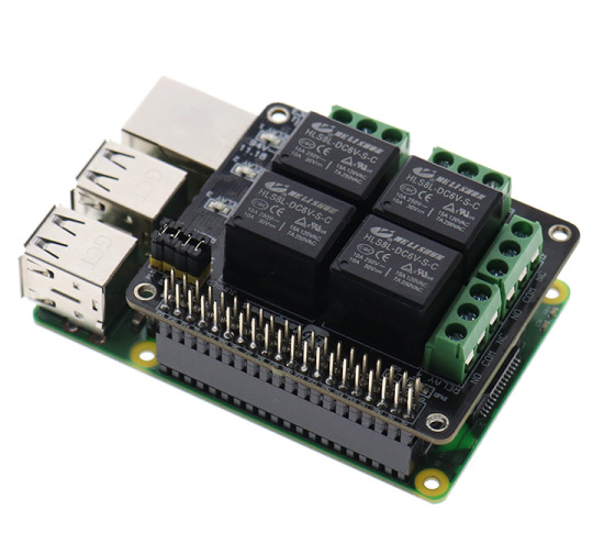
PiRelay provides a solution for controlling high current/voltage devices and makes your home appliances intelligent. It could be a nice solution for controlling devices that could not be directly controlled by RPi's Digital I/Os. The standardized shield form factor enables smooth connection with Raspberry Pi and compatibles.
PiRelay - Relay Shield for Raspberry Pi
#Relay Shield for Raspberry Pi#Raspberry Pirelay#raspberry Pirelay board#PiRelay#relay#raspberry pi relay#relay board#raspberry pi relay board#pi relay#raspberry pi relay control#relay module#pi relay pro#5v relay#relay step by step#raspberry pi relay light#raspberry pi#rpi relay board#piot relay board#solid-state relay#channel relay#relay control#8 channel relay#i2c relay#8 relay#tutorial#mains relay#home automation#relay race#8 relay board
0 notes
Text
Stupid thought
R1 Lack 3d printing enclosure has
- the 16A switch from the back of the printer (to control ac to the power supply)
- three 10A switches (DC to printer logic board, lights, air filter)
There at least WAS an octoprint plugin, Octorelay, that was built around software control of such things, given proper supporting hardware
But I'd still want my switches
Which, by my research, would mean 4 momentary switches, and 4 locking relays.. which require at least 2 normal relays each. And more electronics then I'm comfortable with at the moment. And that doesn't cover an off-only signal from the control computer... gpio via USB, maybe.
OR. Or. I could wire everything up to a raspberry pi pico. The 4 momentary switches, 4 standard relays. 30A ones, even if the 10A components have been fine so far. Program the pico to respond to both switches and act as the proper type of usb device to send my gpio signals. Hmm.
2 notes
·
View notes
Text

I love those flip style clocks, like the one from Groundhog Day. Why? I'm not sure exactly, they're just very cool looking and fit into that facinating retro futuristic electromechanical niche.
We've got one of these at home to show the time and date. The clock is just a standard quartz rotary type, but the day name, day number and month use flippers.
After years of faithful service our clock started to fail at triggering the flippers. After cracking it open I determined it was due to the clock failing to send the flip signal at 12 o'clock.
I decided to put my new Raspberry Pi Pico microcontroller into action by creating a pacemaker!

An LCD screen allows the current time which is set when power is connected

Then at midday and midnight it triggers a relay that activates the flipper mechanism in the clock

Currently it's got a fairly high power draw, which I plan to reduce using longer sleep periods on the Pico. Also I'll remove the LEDs from the relay and turn off the LED light on the LCD.
I've ordered a Li-ion battery pack and charger which I'll be attaching and then fitting the whole thing into the clock.
It's been a great project to work on this and it's not over yet. It's amazing such a cheap little board as the Pico is capable of such useful things. Love it!
1 note
·
View note
Text
Proposal for something Awesome [EDITED - v1.1]
Topic: Facial Recognition Door Knob
My proposal for “Something Awesome Project” would be to working on “Facial Recognition Door Lock by using Raspberry Pi”.
Raspberry Pi is a low cost, credit-card sized computer that enables people to create various electronic devices, with a use of high-level programming language (e.g., Python). Ideally, it is possible to integrate it with a simple electronic circuit having relay as a main component to act as a switch to enable the door knob.
I have not had any chance to work on the project that need both software and hardware area before. So I would like to use this opportunity to work in something that I am personally interested in and to push myself forward. Here is my ideas about how it works which could be change due to the development.
With the use of Raspberry Pi (have not been finalised, might change to arduino R3 if it is better), high-level programming can be implemented on it. This can be use as a core of this project to link between facial recognition software and electronic component (door knob).
I would not finalised how the electronic component and circuit design because there are many options to be selected. So in the early state of the design, I might use an LED light to indicate the door knob functionality (for instance light-on: unlock, light-off:lock), then the circuit is going to be designed after the simple model work correctly and here is what I was thinking about in that state.
Relay module is connected into the board, this is going to act as a switch to enable/disable digital output signal which can connected direct to a door knob part.
I personally would like to use it in creating software part by using tensorflow, since I did self-study on it last year and did some simple image processing in converting hand writing into a text but have no experience in any object detection. However, if I could not do it, OpenCV (I have no experience) is my second plan in creating software part.
Planing
I wish to set out the working on my project as follows
Weeks 3: Doing research about facial recognition API and design the circuit.
Weeks 4-6: implementing software part for facial recognition and electronic circuit (with Raspberry Pi, external camera and relay module integrated.)
Weeks 7-8: Unexpected problems and finishing up
Stages and Milestones. [EDITED]
Basic Goals.
Implementing facial recognition software
Creating simple designed electronic model of Raspberri Pi to run the software above
Extension
Uploading progress and demonstration of the facial recognition in each iteration
Writing tutorial and guide on how to build it.
Marking Criteria [EDITED]
Although I have some knowledges about electronic circuits, I have never worked on any practical hardware project before. I could not confidentially ensure that the project would be eventually end up with well-functioned facial recognition uploaded into electronic circuit board that work correctly with the user. So I have created my marking system.
FL - No attempt
PS - Minimal attempt in the project.
CR - Consistent blogs every week in updating what I have done on doing research and how I manage to design the circuit and software implementation.
DN - Either electronic circuit or software is complete but might not work properly (For example, the software works on laptop but not work on the circuit since the different in version or operating system on the board).
HD - The electronic circuit connect to all the component and be able to work with facial recognition software to enable the digital output signal. An extension part is finished.
1 note
·
View note
Text
Raspberry Pi: A Versatile Computer for DIY Projects
Raspberry Pi is a credit card-sized computer that is designed for DIY projects and educational purposes. It is a powerful, versatile, and affordable device that can be used for a wide range of applications. In this blog, we will discuss what Raspberry Pi is and some of the ways it can be used.
What is Raspberry Pi?
Raspberry Pi is a single-board computer that was created by the Raspberry Pi Foundation in the UK. It is based on ARM processor architecture and can run a variety of operating systems, including Linux and Windows 10. The device comes with a range of input and output ports, including USB, Ethernet, HDMI, and GPIO pins, making it easy to connect to other devices.
What can you do with Raspberry Pi?
Raspberry Pi can be used for a variety of DIY projects and educational purposes. Here are some examples:
Home Automation
Raspberry Pi can be used to create a home automation system that can control lighting, temperature, and other devices. This can be done by using sensors and relays to control the devices, and programming the Raspberry Pi to perform specific tasks.
Media Center
Raspberry Pi can be used to create a media center that can stream movies, TV shows, and music. This can be done by using software such as Kodi or Plex, and connecting the Raspberry Pi to a TV or monitor.
Retro Gaming
Raspberry Pi can be used to create a retro gaming console that can play classic games from the 80s and 90s. This can be done by using software such as RetroPie, and connecting the Raspberry Pi to a TV or monitor.
Robotics
Raspberry Pi can be used to create robots and other autonomous systems. This can be done by using sensors, motors, and other components, and programming the Raspberry Pi to control the devices.
Educational Projects
Raspberry Pi can be used for educational purposes, such as teaching programming and electronics. The device can be used to create simple projects, such as blinking an LED, or more complex projects, such as building a weather station.
In conclusion, Raspberry Pi is a versatile and affordable computer that can be used for a wide range of DIY projects and educational purposes. Whether you want to create a home automation system, a media center, or a retro gaming console, Raspberry Pi is a powerful and flexible device that can help you achieve your goals.
0 notes
Text
IoT Powered Building Management System for Small and Medium Sized Buildings

Building Management Systems (BMS) have been used to automate equipment in large buildings for almost 3 decades, but such systems are not suitable for small and medium sized buildings (of less than 100K sq. ft.). This problem is compounded by the fact that customer’s multiple locations are dispersed across the geography, making it difficult to drive consistent manual behaviour, resulting in challenges such as high energy costs, compliance issues, and asset breakdown.
IoT powered building management system for small and medium sized buildings helps in optimizing energy consumption, maintaining temperature compliances, managing asset health and facilitating digital workflows. It works across protocols and equipment of multiple OEMs. The technology is wireless, plug & play enabling easy deployments and maintenance. Being a hardware light solution, it is cost-effective and delivers a faster return on investment.
IoT Technology that fulfills SMB needs
It’s not easy for small and medium-sized buildings (SMB) to invest a massive sum of money to ensure efficient operations. The Internet of Things (IoT) is a powerful technology that focuses on in-house innovations across edge devices & their networking, cloud platforms, and end-user interfaces. Ensuring building productivity, optimal energy consumption, and automation at reduced cost becomes possible with this smart technology.
The Internet of Things (IoT) comes with:
Wireless Mesh for Sensing and Control
An open-source wireless mesh OpenThread (from Google) develops a mesh-based robust solution that includes a wide variety of battery-powered sensors such as temperature, humidity, luminosity, CO2, etc. It relays data to a gateway using multiple hops on the mesh network.
The whole network is resilient to faults and opens up a broad variety of applications ranging from deploying a large number of sensors inside/outside buildings within a campus to connected street lighting solutions spread across a large municipality.
Industrial Grade Gateway
IoT often comes in a state-of-the-art gateway that is an open platform based on Raspberry Pi Compute Module (contains a 32-bit Quad-core processor, 1GB RAM, and onboard disk, and operates on a Linux-based Operating system). It supports a wide variety of connectivity options through the plug & play modules such as 4G through an mPCIE card, WiFi/Bluetooth/OpenThread through an M.2 card, and onboard LAN.
The IoT gateway supports multiple features for rugged operation in difficult environments in small and medium-sized buildings, including dual SIM connectivity, battery-backed RTC, onboard watchdog, battery backup, and isolated RS485 connectivity.
IoT Stack on Cloud
Cloud-connected IoT stack developed using open-source technologies delivers standard services such as alerts, time series databases, reports, and dashboards.
This integrated analytical platform provides scalability to small and medium-sized buildings. The configurable dashboard platform allows facility managers to customize different user interfaces across and within the customer through drag-and-drop elements without writing a single line of code.
Choosing a cloud-based IoT stack means managing more than 200 Mn data points every single day that can scale up to 100X very easily.
Plug & Play Platform
Typical deployment timelines in buildings and chains are a bit long (actually depends on the sq. ft area). On-site hardware systems consisting of the industrial-grade gateway and sensing/control endpoints on the multi-hope, wireless mesh enable faster deployment, bringing down the timeline of legacy hardware by 50-80%.
This plug-and-play platform enables remote deployment, troubleshooting, and maintenance of the edge hardware.
Is a small size building actually worth a BMS?
Well, the honest answer is “no.” Building management systems haven’t been designed for small buildings. The ideal solution is the implementation of IoT BMS, which is cost effective and ROI based solution.
Get Zenatix IoT BMS For Your Small And Medium Size Buildings Now!
Zenatix’s powerful IoT-based solutions can help you implement the right BMS for your small and mid-size buildings. Get in touch with us today!
View Source : https://www.zenatix.com/iot-powered-building-management-system-for-small-and-medium-sized-buildings/
0 notes
Text
Adding 4 separate electrical outlets to one box + some hidden connections. HELP :)

Hi!
I'm planning to build a wall terminal with relay operated outlets (4, single outlets), a built in monitor, a relay operated light switch, relay operated christmas lights (for cozyness), raspberry pi (to controll all of it and a small fan (to cool the pi and relays).
I want to place this terminal where I have a single (grounded) outlet with a lightswitch. I want to keep this outlet disconnected from the relays to have at least one functioning outlet if anything goes wrong with the Raspberry Pi (which controlls the remaining 4 outlets.
I'm planning to connect this whole terminal on one outlet box. So I want to connect all these peripherals in parallel on this box. The RPi, cooling fan, monitorand Christmas lights have a low energy consumption so I'm not scared that these will fry my relays (10A, 250VAC on a 220V circuit) or the powercables. However, should I connect my heater (2000W Max) or vaccuum cleaner (800W Max) or both to the outlets, then I am scared it will put too high of a load on the power cables (which have a maximum of 3600W since my breaker is rated for 16A on a 220V circuit).
So my question is whether it is safe to put all of these peripherals on one outlet box with the heater and vaccuum cleaner as highest potential power consumers.
If not, would it make sense to split both the Neutral and Hot lines into two lines from which one of the lines are connected to the low energy peripherals and the other lines connected to the 4 outlets (like in the image below)?
https://preview.redd.it/rh0dv2lvmc381.jpg?width=593&format=pjpg&auto=webp&s=3a02f2cde6cc59d8d39e32ba7c6be6a71827f01d
Or doesn't it make a difference if I put all peripherals on the same parallel group?
Thanks in advance for your answer!
EDIT: I forgot to add the non-relay outlet and RPi in the circuit, so I added it in the picture :)
submitted by /u/JustAhero4Fun [link] [comments]
from Electricians of Reddit https://ift.tt/2ZTTmEA
0 notes
Text
Channel Mosfet

MOSFET Tizen deezer 2.
N Channel Mosfet Circuit
P Channel Mosfet Operation
N Channel Mosfet Symbol
ST's P-channel MOSFET portfolio is optimized to meet a broad range of requirements for load switch, linear regulator, automotive applications and specifically designed for portable applications. The MOSFET is another category of field-effect transistor.There are two types of MOSFET, Enhancement mode MOSFET and Depletion mode MOSFET. Major Brands BS250 N-Channel MOSFET Transistor, TO-92, 3 Pin, 5.2 mm H x 4.2 mm W x 4.8 mm L (Pack of 10) 5 $8 79 ($0.88/Transistor). This Article Shows A Detailed And Clear Explanation Of MOSFET Working, Structure, Analysis, Example, Applications, Benefits And Many Others. If you need to switch high current and or high voltage loads with a micro controller you'll need to use some type of transistor. I'm going to be covering how to use a MOSFET since it's a better.
The MOSFET is an important element in embedded system design which is used to control the loads as per the requirement. Many of electronic projects developed using MOSFET such as light intensity control, motor control and max generator applications. The MOSFET is a high voltage controlling device provides some key features for circuit designers in terms of their overall performance. This article provides information about different types of MOSFET applications.
MOSFET and Its Applications
The MOSFET (Metal Oxide Semiconductor Field Effect Transistor) transistor is a semiconductor device which is widely used for switching and amplifying electronic signals in the electronic devices.The MOSFET is a three terminal device such as source, gate, and drain. The MOSFET is very far the most common transistor and can be used in both analog and digital ckt.
The MOSFET works by varying the width of a channel along which charge carriers flow (holes and electrons). The charge carriers enter the channel from the source and exits through the drain. The channel width is controlled by the voltage on an electrode is called gate which is located between the source and drain. It is insulated from the channel near an extremely thin layer of metal oxide. There is a different type of MOSFET applications which is used as per the requirement.
Types of MOSFET Devices
The MOSFET is classified into two types such as;
Depletion mode MOSFET
Enhancement mode MOSFET
Depletion Mode: When there is zero voltage on the gate terminal, the channel shows its maximum conductance. As the voltage on the gate is negative or positive, then decreases the channel conductivity.
Depletion Mode MOSFET
Enhancement Mode
When there is no voltage on the gate terminal the device does not conduct. Twitch deezer. More voltage applied on the gate terminal, the device has good conductivity.
Enhance Mode MOSFET
MOSFET Working Principle
The working of MOSFET depends upon the metal oxide capacitor (MOS) that is the main part of the MOSFET. The oxide layer presents among the source and drain terminal. It can be set from p-type to n-type by applying positive or negative gate voltages respectively. When apply the positive gate voltage the holes present under the oxide layer with a repulsive force and holes are pushed downward through the substrate. The deflection region populated by the bound negative charges which are allied with the acceptor atoms.
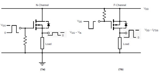
P- Channel MOSFET
The P-Channel MOSFET consist negative ions so it works with negative voltages. When we apply the negative voltage to gate, the electrons present under the oxide layer through pushed downward into the substrate with a repulsive force. The deflection region populates by the bound positive charges which are allied with the donor atoms. The negative voltage also attracts holes from p+ source and drain region into the channel region.

P-Channel MOSFET
N- Channel MOSFET
When we apply the positive gate voltage the holes present under the oxide layer pushed downward into the substrate with a repulsive force. The deflection region is populated by the bound negative charges which are allied with the acceptor atoms. The positive voltage also attracts electrons from the n+ source and drain regions into the channel. Now, if a voltage is applied among the drain and source the current flows freely between the source and drain and the gate voltage controls the electrons in the channel. In place of positive voltage if we apply a negative voltage (hole) channel will be formed under the oxide layer.
N-Channel MOSFET
MOSFET Applications
The applications of the MOSFET used in various electrical and electronic projects which are designed by using various electrical and electronic components. For better understanding of this concept, here we have explained some projects.
MOSFET Used as a Switch
In this circuit, using enhanced mode, a N-channel MOSFET is being used to switch the lamp for ON and OFF. The positive voltage is applied at the gate of the MOSFET and the lamp is ON (VGS =+v) or at the zero voltage level the device turns off (VGS=0). If the resistive load of the lamp was to be replaced by an inductive load and connected to the relay or diode to protect the load. In the above circuit, it is a very simple circuit for switching a resistive load such as LEDs or lamp. But when using MOSFET to switch either inductive load or capacitive load protection is required to contain the MOSFET applications. If we are not giving the protection, then the MOSFET will be damaged. For the MOSFET to operate as an analog switching device, that needs to be switched between its cutoff region where VGS =0 and saturation region where VGS =+v.
Auto Intensity Control of Street Lights using MOSFET
Now-a-days most of lights placed on the highways are done through High Intensity Discharge lamps (HID), whose energy consumption is high. Its intensity cannot be controlled according to the requirement, so there is a need to switch on to an alternative method of lighting system, i.e., to use LEDs. This system is built to overcome the present day drawbacks of HID lamps.
Auto Intensity Control of Street Lights using MOSFET
This project is designed to control the lights automatically on the highways using microprocessor by variants of the clock pulses. In this project, MOSFET plays major role that is used to switch the lamps as per the requirement. The proposed system using a Raspberry Pi board that is a new development board consist a processor to control it. Here we can replace the LEDs in place of HID lamps which are connected to the processor with the help of the MOSFET. The microcontroller release the respective duty cycles, then switch the MOSFET to illuminate the light with bright intensity
Marx Generator Based High Voltage Using MOSFETs
The main concept of this project is to develop a circuit that delivers the output approximately triple to that of the input voltage by Marx generator principle. It is designed to generate high-voltage pulses using a number of capacitors in parallel to charge during the on time, and then connected in series to develop a higher voltage during the off period. If the input voltage applied is around 12v volts DC, then the output voltage is around 36 volts DC.
This system utilizes a 555 timer in astable mode, which delivers the clock pulses to charge the parallel capacitors during on time and the capacitors are brought in a series during the off time through MOSFET switches; and thus, develops a voltage approximately triple to the input voltage but little less, instead of exact 36v due to the voltage drop in the circuit. The output voltage can be measured with the help of the multimeter.
EEPROM based Preset Speed Control of BLDC Motor
The speed control of the BLDC motor is very essential in industries as it is important for many applications such as drilling, spinning and elevator systems. This project is enhanced to control the speed of the BLDC motor by varying the duty cycle.
EEPROM based Preset Speed Control of BLDC Motor
The main intention of this project is to operate a BLDC motor at a particular speed with a predefined voltage . Therefore, the motor remains in an operational state or restarted to operate at the same speed as before by using stored data from an EEPROM.
Before using Praat to do sound analysis, we have to be clear about know that what information we can get from Praat. Table 1 presents some major acoustic variables we usually use to analyze the speech sounds. 49) for visual presentation of the variables. Praat is a free software package used for speech analysis in phonetics. It is designed and continuously developed by Paul Boersma and David Weenink of the University of Amsterdam. It is a flexible tool that offers a broad range of standard and non-standard procedures such as spectrographic analysis, speech synthesis, articulatory synthesis and neural networks. Praat allows you to divide up the sound signal into temporal stretches or intervals, and to assign text or labels to these intervals. It does this by means of what it calls a TextGrid. The basic idea is that one might want to divide a signal into intervals in more than one way. Praat scripts Phonetics Laboratory Scripts and batch processes are a handy way of saving time while performing repetitive operations. In this page we share some of the Praat scripts we use in our Lab. All the scripts include instructions (either at the begining of the file or in the first form of the script). PRAAT is a very flexible tool to do speech analysis. It offers a wide range of standard and non-standard procedures, including spectrographic analysis, articulatory synthesis, and neural networks. This tutorial specifically targets clinicians in the field of communication disorders who want to learn more about the use of PRAAT as part of an. Praat phonetics.
The speed control of the DC motor is achieved by varying the duty cycles (PWM Pulses) from the microcontroller as per the program. The microcontroller receives the percentage of duty cycles stored in the EEPROM from inbuilt switch commands and delivers the desired output to switch the driver IC in order to control the speed of the DC motor. If the power supply is interrupted, the EEPROM retains that information to operate the motor at the same speed as before while the power supply was available.
LDR Based Power Saver for Intensity Controlled Street Light
In the present system, mostly the lightning-up of highways is done through High Intensity Discharge lamps (HID), whose energy consumption is high and there is no specialized mechanism to turn on the Highway light in the evening and switch off in the morning. Recoverit download mac.
LDR Based Power Saver for Intensity Controlled Street Light
N Channel Mosfet Circuit

P Channel Mosfet Operation
Its intensity cannot be controlled according to the requirement, so there is a need to switch to an alternative method of lighting system, i.e., by using LEDs. This system is built to overcome the present day, drawback of HID lamps.
This system demonstrates the usage of LEDs (light emitting diodes) as light source and its variable intensity control, according to the requirement. LEDs consume less power and its life is more, as compared to conventional HID lamps.
The most important and interesting feature is its intensity that can be controlled according to requirement during non-peak hours, which is not feasible in HID lamps. A light sensing device LDR (Light Dependent Resistance) is used to sense the light. Its resistance reduces drastically according to the daylight, which forms as an input signal to the controller . A cluster of LEDs is used to form a street light. The microcontroller contains programmable instructions that controls the intensity of lights based on the PWM (Pulse width modulation) signals generated.
The intensity of light is kept high during the peak hours, and as the traffic on the roads tend to decrease in late nights; the intensity also decreases progressively till morning. Finally the lights get completely shut down at morning 6 am, to resume again at 6pm in the evening. The process thus repeats.
SVPWM (Space Vector Pulse Width Modulation)
The Space Vector PWM is a sophisticated technique for controlling AC motors by generating a fundamental sine wave that provides a pure voltage to the motor with lower total harmonic distortion. This method overcomes the old technique SPWM to control an AC motor that has high-harmonic distortion due to the asymmetrical nature of the PWM switching characteristics.
In this system, DC supply is produced from the single-phase AC after rectification, and then is fed to the 3-phase inverter with 6 numbers of MOSFETs. For each phase, a pair of MOSFETare used, and, therefore, three pairs of MOSFETs are switched at certain intervals of time for producing three-phase supply to control the speed of the motor. This circuit also gives light indication of any fault that occurs in the control circuit
N Channel Mosfet Symbol
Therefore, this is all about types of MOSFET applications, Finally, we will conclude that, the MOSFET requires high voltage whereas transistor requires low voltage and current. As compared to a BJT, the driving requirement for the MOSFET is much better.Furthermore, any queries regarding this article you can comment us by commenting in the comment section below.
0 notes
Text
Relay Shield for Raspberry Pi | PiRelay
Relay Shield for Raspberry Pi utilizes four high quality relays and provides NO/NC interfaces that control the load of high current. Which means it could be a nice solution for controlling devices that couldn’t be directly controlled by IIC bus. Standardized shield form factor enables smoothly connection with the Raspberry Pi. PiRelay shield also has four dynamic indicators show the on/off state of each relay.
#Relay Shield for Raspberry Pi#Raspberry Pirelay#raspberry Pirelay board#PiRelay#Raspberry Pi#Raspberry#Pi#relay#raspberry pi relay#relay board#raspberry pi relay board#pi relay#raspberry pi relay control#relay module#pi relay pro#5v relay#relay step by step#raspberry pi relay light#rpi relay board#piot relay board#solid-state relay#channel relay#relay control#8 channel relay
0 notes