#Arduino ESP8266
Explore tagged Tumblr posts
Visit Tumblr Blog
Explore Tumblr blogs with no restrictions, modern design and the best experience.
Last Seen Tumblr Blogs


Fun Fact
Tumblr Inc. is funded by 13 investors.
Text
2 notes
·
View notes
Video
youtube
Air Pollution Monitoring using Arduino
#youtube#Air Pollution Monitoring using Arduino & ESP8266 | MQ135 | MQ2 | MQ4 | MQ7 | TCP Telnet Terminal APP | IoT Based Air Pollution/Quality Monit
0 notes
Text
Understanding ESP32 Pin Configuration: A Developer's Guide
The ESP32 microcontroller has become a cornerstone of IoT development, thanks to its versatility and powerful features. One of the most crucial aspects of working with ESP32 is understanding its pin configuration and capabilities. Let's dive into the essential aspects of ESP32 pins that every developer should know.

GPIO Pins Overview
The ESP32 boasts up to 34 GPIO (General Purpose Input/Output) pins, but not all are available for use in most development boards. Some key points about ESP32 pins:
GPIO 6-11: Reserved for internal SPI flash connection
GPIO 34-39: Input-only pins with no internal pull-up/pull-down resistors
ADC Capabilities: Two 12-bit SAR ADCs, supporting 18 measurement channels
Touch Sensors: Up to 10 capacitive touch GPIOs
Special Function Pins
Several pins serve dual purposes or have specific functions:
Boot Mode Pins GPIO 0: Bootloader mode when pulled low during reset GPIO 2: Connected to on-board LED in many development boards
UART Pins GPIO 1 (TX) and GPIO 3 (RX): Default UART0 communication Often used for flashing and debugging
SPI Pins VSPI: GPIO 5 (CS), 18 (CLK), 19 (MISO), 23 (MOSI) HSPI: GPIO 14 (CLK), 12 (MISO), 13 (MOSI), 15 (CS)
Best Practices for Pin Usage
Strapping Pins Always check the strapping pin status before using GPIO 0, 2, 4, 5, 12, and 15. These pins may affect boot behavior if incorrectly configured.
Input-Only Pins When designing sensor interfaces, prefer GPIO 34-39 for analog inputs as they're input-only and less susceptible to noise.
Pull-up/Pull-down Configuration
ADC Usage ADC1: Can be used with Wi-Fi/Bluetooth active ADC2: Only available when Wi-Fi/Bluetooth is disabled
Common Pitfalls to Avoid
Don't use GPIO 6-11 in your projects as they're connected to the internal SPI flash.
Avoid using strapping pins for critical functions that can't be changed during boot.
Remember that GPIO 34-39 don't have internal pull-up/pull-down resistors.
Be cautious with voltage levels - ESP32 pins operate at 3.3V.
Conclusion
Understanding ESP32 pinout is fundamental for successful project development. By following these guidelines and best practices, you can avoid common issues and make the most of your ESP32's capabilities. Remember to always consult the official ESP32 technical reference manual for detailed specifications and updates.
#ESP32 #PinConfiguration #DevelopersGuide #Microcontrollers #EmbeddedSystems #IoT #Programming #Hardware #Electronics #Arduino #ESP32S2 #ESP32C3 #ESP32C2 #ESP32C6 #ESP32S3 #ESP32H2 #ESP32P1
#ESP32#microcontroller#pinconfiguration#GPIO#ADC#DAC#I2C#SPI#UART#PWM#analog#digital#input#output#microcontrollers#embeddedsystems#IoT#InternetOfThings#electronics#hardware#software#programming#development#Arduino#ESP8266#RaspberryPi#microcontrollerprogramming#embeddedprogramming#IoTdevelopment#electronicdesign
1 note
·
View note
Video
youtube
Ejemplo de webserver para wemos d1 esp8266 en arduino
#youtube#ejemplo#ejemplos#arduino#wemos d1#web server#web server en arduino#programas arduino#ejemplos arduino#esp8266
1 note
·
View note
Text
Ouija 8266
In 2021, I created this ESP8266 programmer that looks like a Ouija board planchette. You can attach an ESP-01 module, plug in an FTDI cable, and program the module from your computer using the Arduino IDE – then wear the programmer as an earring!

Here's the full write-up:
1 note
·
View note
Text
youtube
#Car cooling systems#Cooling fan resistor#DIY tester#Engine Control Unit#Coolant Temperature Sensor#ESP8266 Node MCU#Relay modules#DC motor#Temperature regulation#Automotive engineering#DIY projects#Engine temperature management#Arduino#Youtube
0 notes
Video
youtube
किसी भी पुरानी कार को बनाओ wifi कार | using Node Mcu
0 notes
Text
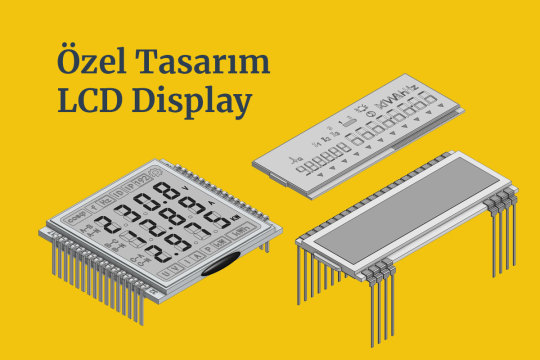
Custom Design LCD Display #lcd #customlcd #display #lcddisplay #lcdmodule #speciallcd #glasslcd #camlcd #backlight #lcdisplay https://www.signal.com.tr/ozel_tasarim_lcd_customized_lcd
#lcddisplay#lcd monitor#lcdmodule#lcdglass#customlcd#display#electronic#engineering#electronicengineering#display technology#screen#lcd#arduino#esp32#esp8266
0 notes
Text

Читаю книги. Давно уже не был на даче и потому не собираю свой трицикл. С врачами пока не понятно, что они хотят со мной делать. На работе тоже ничего особо не понятно. Наверное единственное где мне хоть что-то внятно - это мои отношения.
Пытаюсь вспомнить к��к программировать на Lua но упрямая esp32 не поддается. Да что уж там, не помню толком как на esp8266 то писать. Потратил на них суммарно сутки времени. Результат дальше моргания встроенным светодиодом- не ушёл. А мне надо по i2c подключить хотябы один экран. Но пока не удается вкорячить библиотеки найденные на просторах сети. Думаю может потратить пару дней и попробовать обойтись без них... Но боюсь моих знаний не хватит и я просто выкину время. Можно конечно плюнуть и прошить их на arduino. Но этого результата не хочу. Хочу Lua.
#программирование#личный блог#личный дневник#личный тамблер#мой tumblr#мой блог#мой тамблер#моя жизнь#русский тамблер#русский текст#русский тумблер#русский tumblr#русский пост#русский блог#тумбурочка#турумбочка#тамблер на русском#мои мысли#личные мысли#личный пост#дневничок#дневник
17 notes
·
View notes
Text
Essential Electronic Items for IoT and Electronics Enthusiasts
Are you diving into the world of Internet of Things (IoT) and electronics? Whether you are a seasoned engineer or simply beginning out, having a stable list of essential components is key to bringing your initiatives to existence. Here’s a curated list of electronic objects that each maker and tech enthusiast ought to have of their toolkit:
1. Microcontrollers
Arduino Uno: Great for novices and versatile for diverse projects.
Raspberry Pi: Ideal for more complex duties and going for walks complete operating structures.
ESP8266/ESP32: Perfect for wireless communication and IoT projects.
2. Sensors
DHT22: For temperature and humidity readings.
PIR Sensor: Useful for movement detection.
Ultrasonic Distance Sensor: Measures distances with high accuracy.
3. Actuators
Servo Motors: For unique manage in robotics and mechanical structures.
Stepper Motors: Ideal for applications requiring particular movement.
Solenoids: Good for growing mechanical actions and locks.
4. Displays
LCD Display: Useful for showing records and debugging.
OLED Display: Compact and clean for exact photographs and texts.
5. Connectivity Modules
Bluetooth Module (HC-05/HC-06): For short-range wi-fi communication.
Wi-Fi Module (ESP8266): Connects gadgets to the internet.
GSM Module: Enables verbal exchange over mobile networks.
6. Power Supplies
Battery Packs: Various types for transportable electricity.
Voltage Regulators: Ensure solid voltage ranges in your circuits.
Power Banks: Handy for charging and powering devices on the move.
7. Prototyping Tools
Breadboards: Essential for prototyping with out soldering.
Jumper Wires: For making connections on breadboards.
Soldering Kit: For everlasting connections and circuit meeting.
eight. Additional Components
Resistors, Capacitors, and Diodes: Fundamental for circuit design and stability.
Transistors: Key for switching and amplification tasks.
Connectors and Switches: For interfacing and controlling circuits.
By preserving these objects handy, you'll be nicely-prepared to address a huge range of IoT and electronics projects. Whether you're constructing smart domestic devices, wearable tech, or computerized structures, having the right additives can make all the difference.
#IoT#Electronics#Arduino#RaspberryPi#ESP32#Sensors#Actuators#Displays#ConnectivityModules#PowerSupplies#Prototyping#Tech#DIY#Makers#Engineering#ElectronicComponents#TechProjects
2 notes
·
View notes
Video
youtube
IoT Based Air Pollution Monitoring System using ESP8266
#youtube#IoT Based Air Pollution Monitoring System using ESP8266 & Arduino with GSM - SMS📱Notification 🔔Alert https://www.youtube.com/watch?v=xxVCz
0 notes
Text
Hug-sensing IoT Parihug toy (w Xyla Foxlin)
Here’s how to make your own telepresence hug toy. Each circuit connects to the Arduino IoT Cloud and translates your hug into a soothing vibration on the other toy. Xyla Foxlin originally developed this project as a crowdfunded product, and we collaborated to bring this DIY version to life. To make this project, you will need 2x of each: MPRLS ported pressure sensor Feather HUZZAH ESP8266…

View On WordPress
2 notes
·
View notes
Text
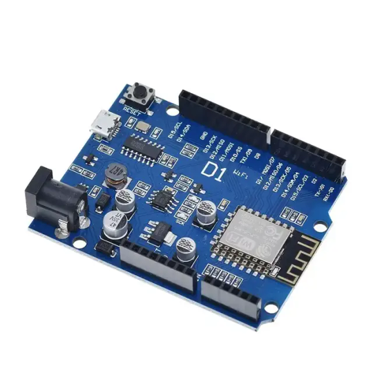
Wemos D1 Wifi Dev Board for Esp8266 IOT Module Online price is 10 units MOQ. Specification: Based on ESP-8266EX Compatible with Arduino,can be program by arduino ide. I/O Pin:11pcs Working Voltage:3.3V Input:7-24V Flash:4MB SRAM:32KB DRAM:80KB Clock Frequency:80MHz/160Mhz Network:802.11b/g/n Other development board you may interest: Interested with much more quantity,contact us to talk price.Know more about company site here. Read the full article
1 note
·
View note
Text
Getting Started with Embedded Systems Programming

Embedded systems programming is the backbone of modern electronics. From smartwatches to washing machines, embedded systems power the intelligent functions of countless everyday devices. This guide will introduce you to the basics of embedded programming, key tools, and how to begin building your own embedded applications.
What is an Embedded System?
An embedded system is a computer integrated into a larger system or device, performing dedicated functions. Unlike general-purpose computers, embedded systems are designed for specific tasks, often with constraints on power, memory, and processing.
Examples of Embedded Systems:
Microcontrollers in home appliances
Sensor-based devices (e.g., temperature sensors, motion detectors)
Medical equipment
Automotive control systems
IoT (Internet of Things) gadgets
Core Components of an Embedded System
Microcontroller or Microprocessor: The brain of the embedded system (e.g., Arduino, STM32, ESP32).
Memory: RAM and ROM to store instructions and data.
Input/Output Interfaces: Connects to sensors, displays, motors, and communication modules.
Software: Custom firmware developed for specific functions, typically in C or C++.
Popular Programming Languages
C: Most widely used due to its efficiency and low-level hardware access.
C++: Used when object-oriented design is required.
Assembly: For highly optimized or time-critical routines.
MicroPython: Python for microcontrollers (e.g., ESP8266, Micro:bit).
Getting Started with Embedded Programming
Select Your Platform:
Beginners: Arduino (easy setup, wide community support)
Advanced: STM32, Raspberry Pi Pico, ESP32
Set Up Your Development Environment:
Install IDEs like Arduino IDE, PlatformIO, STM32CubeIDE
Download necessary drivers and board support packages
Write and Upload Code: Create simple programs like blinking an LED, then expand to sensors, displays, and communication modules.
Example: Blink an LED with Arduino
void setup() { pinMode(13, OUTPUT); // Set pin 13 as output } void loop() { digitalWrite(13, HIGH); // Turn LED on delay(1000); // Wait for 1 second digitalWrite(13, LOW); // Turn LED off delay(1000); // Wait for 1 second }
Tools and Debugging
Serial Monitor: For real-time debugging and logging.
Oscilloscope & Logic Analyzer: For electrical signal inspection.
In-Circuit Debuggers: Like JTAG or ST-Link for low-level debugging.
Best Practices
Write modular and readable code.
Use debouncing for physical inputs like buttons.
Handle memory carefully to avoid overflows.
Optimize power usage in battery-powered devices.
Conclusion
Embedded systems programming is both fun and powerful, offering endless possibilities for innovation in hardware and software. Whether you’re building a home automation project or diving into the world of IoT, understanding the basics of embedded programming gives you the foundation to create smart, responsive devices.
0 notes
Text
MAX30100 am Arduino: Blutsauerstoff und Herzfrequenz messen leicht gemacht

Mit dem MAX30100 steht ein kompakter Sensor zur Verfügung, der sowohl die Herzfrequenz als auch den Blutsauerstoffgehalt (SpO₂) messen kann – ideal für einfache Gesundheits- und Fitnessprojekte mit dem Arduino. Ob die Werte dabei wirklich zuverlässig sind, schauen wir uns in diesem Beitrag genauer an. Ich zeige dir, wie du das MAX30100 Breakout Board anschließt, die Messwerte ausliest und sie im seriellen Monitor anzeigst. Die Kommunikation erfolgt über I²C, und dank der integrierten Energiesparfunktionen eignet sich der Sensor auch für batteriebetriebene Projekte.

MAX30100 Herfrequenz und Blutsauerstoff Sensor am Arduino Einen ähnlichen Sensor habe ich bereits im Beitrag „Arduino Lektion 79: Herzschlag-Pulssensor“ vorgestellt. Damals ging es um einen einfachen Herzschlagsensor, der per Infrarotlicht den Puls erkennen konnte. Der MAX30100 geht jedoch einen Schritt weiter: Er kombiniert Puls- und SpO₂-Messung in einem einzigen Modul und bietet damit deutlich mehr Möglichkeiten für eigene Projekte.
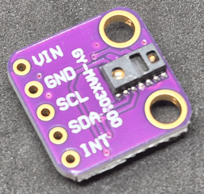
Vorderseite MAX30100 Herzfrequenz & Blutsauerstoff Sensor
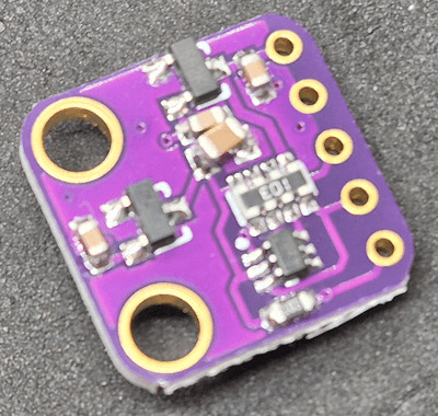
Rückseite des MAX30100 Sensors Hinweis: Der MAX30100 ist ein Sensor für den Hobby- und DIY-Bereich und nicht für den medizinischen Einsatz geeignet. Die gemessenen Werte können Anhaltspunkte liefern, ersetzen jedoch keinesfalls eine ärztliche Untersuchung oder professionelle Überwachung. Medizinisch zugelassene Geräte aus der Apotheke oder dem Sanitätshaus unterliegen strengen Normen und regelmä��igen technischen Prüfungen – etwas, das wir im Hobbybereich nicht leisten können. Nutze den Sensor daher ausschließlich für experimentelle oder edukative Zwecke.
Vielseitige Einsatzmöglichkeiten des MAX30100
Der MAX30100 eignet sich hervorragend für Projekte rund um die Überwachung von Vitalwerten, etwa in DIY-Fitness-Trackern, Schlafüberwachungen oder einfachen medizinischen Anwendungen im Hobbybereich. Durch seine kompakte Bauweise lässt sich der Sensor gut in tragbare Geräte integrieren. Neben dem Arduino ist der MAX30100 auch kompatibel mit Mikrocontrollern wie dem ESP32 oder ESP8266 sowie mit dem Raspberry Pi. Dank der standardisierten I²C-Schnittstelle ist die Anbindung an unterschiedliche Plattformen unkompliziert – ganz gleich, ob du mit der Arduino IDE, MicroPython oder Python arbeitest. Damit ist der Sensor eine ausgezeichnete Wahl für eine Vielzahl von Elektronikprojekten, bei denen es auf Puls- und Sauerstoffsättigungsmessung ankommt.
Technische Daten des MAX30100 Sensors
Bevor wir den Sensor in Betrieb nehmen, lohnt sich ein kurzer Blick auf die technischen Eckdaten. Der MAX30100 kombiniert einen Pulssensor und einen SpO₂-Sensor in einem kompakten Modul und ist für den Betrieb an Mikrocontrollern wie dem Arduino bestens geeignet. Die folgende Tabelle gibt einen Überblick über die wichtigsten Spezifikationen: EigenschaftWert / BeschreibungVersorgungsspannung3,3 VKommunikationI²C (Adresse: 0x57)MessfunktionenHerzfrequenz und Blutsauerstoffsättigung (SpO₂)LED-TypenRote LED und Infrarot-LEDAbtastrateProgrammierbarLED-StromProgrammierbar für EnergieeinsparungStandby-StromSehr niedrig (ultra-low current)Abmessungenca. 14 × 14 × 3,9 mm Der Sensor ist ideal für tragbare Projekte geeignet und lässt sich durch die I²C-Schnittstelle unkompliziert integrieren – auch in bestehende Schaltungen.
Bezug und Lieferumfang des MAX30100
Den Sensor bekommst du recht günstig auf Aliexpress.com und ebay.de. In meinem Fall habe ich mir diesen bei ebay.de für 5,92 € inkl. Versandkosten* geholt. Hinweis von mir: Die mit einem Sternchen (*) markierten Links sind Affiliate-Links. Wenn du über diese Links einkaufst, erhalte ich eine kleine Provision, die dazu beiträgt, diesen Blog zu unterstützen. Der Preis für dich bleibt dabei unverändert. Vielen Dank für deine Unterstützung!
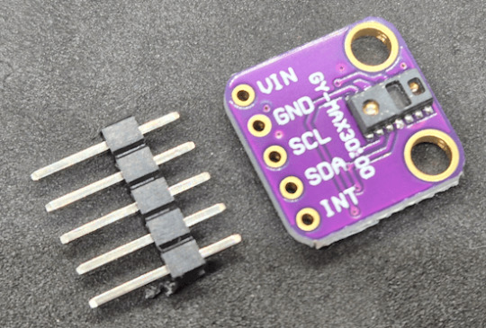
Lieferumfang des MAX30100 Sensors
Überblick über den MAX30100 – Aufbau und Pinbelegung
Damit du den MAX30100 korrekt anschließen und in deine Schaltung integrieren kannst, werfen wir einen genaueren Blick auf den Aufbau des Breakout-Boards. Auf dem folgenden Bild habe ich die wichtigsten Komponenten und Pins für dich beschriftet:
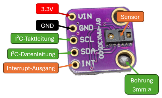
Aufbau & Pinout des MAX30100 Sensors Beschreibung der markierten Elemente: - VIN – Versorgungsspannung (3,3 V) - GND – Masse - SCL – I²C-Taktleitung - SDA – I²C-Datenleitung - INT – Interrupt-Ausgang (optional, wird in einfachen Projekten oft nicht verwendet) - MAX30100 Chip – Der eigentliche Sensor, der rote und IR-LEDs sowie den Fotodetektor enthält - Status-LED – Zeigt an, ob der Sensor aktiv ist (je nach Board vorhanden) Achte darauf, dass du den Sensor nicht direkt mit 5 V versorgst, da er nur mit 3,3 V betrieben werden darf. Manche Breakout-Boards haben zwar einen Spannungsregler integriert – überprüfe das aber unbedingt vorher im Datenblatt deines Moduls.
Schaltung: MAX30100 am Arduino UNO R3 anschließen
Für den ersten Test schließen wir den MAX30100 Sensor an einen Arduino UNO R3 an. Die gemessenen Werte – Puls und Blutsauerstoff – lassen sich bequem über den seriellen Monitor der Arduino IDE ausgeben oder alternativ mit dem seriellen Plotter grafisch als Liniendiagramm darstellen. Benötigte Komponenten - 1 × Arduino UNO R3* - 1 × MAX30100* - 1 × 170-Pin Mini-Breadboard* - 4 × Breadboardkabel* männlich–männlich, 10 cm (Farben: Rot, Schwarz, Gelb, Grün) Verdrahtung

Schaltung - Arduino UNO R3 mit MAX30100 Sensor MAX30100 PinFunktionArduino UNO R3 PinKabel-FarbeVINVersorgung 3,3 V3.3VRotGNDMasseGNDSchwarzSDAI²C DatenleitungA4 (SDA)GelbSCLI²C TaktleitungA5 (SCL)Grün
Vorbereitung: Leeres Programm zur Rücksetzung der Pins hochladen
Bevor wir den MAX30100 anschließen und mit der eigentlichen Programmierung beginnen, empfehle ich einen kleinen, aber hilfreichen Zwischenschritt: Lade zunächst ein leeres Programm auf deinen Arduino, um sicherzustellen, dass alle Pins wieder auf ihren Standardzustand (Input) zurückgesetzt werden. Gerade wenn zuvor ein anderes Sketch geladen war, in dem Pins als Ausgänge oder mit bestimmten Pegeln konfiguriert wurden, kann das bei sensiblen Sensoren wie dem MAX30100 zu unerwünschtem Verhalten oder sogar Schäden führen. void setup() { // put your setup code here, to run once: } void loop() { // put your main code here, to run repeatedly: }
Bibliothek für den MAX30100 installieren
Für die Programmierung des MAX30100-Sensors findest du im Bibliotheksverwalter der Arduino IDE zahlreiche Bibliotheken. Ich verwende in diesem Beitrag die einfach gehaltene Bibliothek aus dem GitHub-Repository oxullo/Arduino-MAX30100. Diese Bibliothek ist schlank, verständlich aufgebaut und bringt zudem einige Beispielsketches mit, die wir fast direkt verwenden können – ideal für den Einstieg in die Arbeit mit dem Sensor.
Auslesen der Werte für Herzfrequenz und Blutsauerstoff in der Arduino IDE
Starten wir zunächst mit einem einfachen Beispiel aus der Bibliothek von oxullo für den MAX30100 Sensor. Hier wird auf dem seriellen Monitor die Daten ausgegeben. Jedoch möchte ich diese im seriellen Plotter ausgeben.
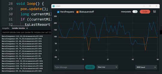
Ausgabe der Herzfrequenz & Blutsauerstoff des MAX30100 Sensors in der Arduino IDE Beispiel Programm für den MAX30100 Sensor am Arduino // Inkludiere die benötigten Bibliotheken für I²C-Kommunikation und den MAX30100-Sensor #include #include "MAX30100_PulseOximeter.h" // Intervall für die Ausgabe der Messwerte (in Millisekunden) #define REPORTING_PERIOD_MS 1000 // Erzeuge ein Objekt für den Sensor PulseOximeter pox; // Variable, um den Zeitpunkt der letzten Ausgabe zu speichern uint32_t tsLastReport = 0; // Diese Funktion wird aufgerufen, wenn ein Herzschlag erkannt wird void onBeatDetected() { Serial.println("Beat!"); // Ausgabe im seriellen Monitor } void setup() { // Initialisiere die I²C-Schnittstelle Wire.begin(); // Starte die serielle Kommunikation mit 9600 Baud Serial.begin(9600); Serial.print("Initialisierung des Sensors MAX30100"); // Versuche, den Sensor zu starten if (!pox.begin()) { Serial.println("Sensor wurde nicht gefunden!"); Serial.println("Überprüfe die Verkabelung!"); // Endlosschleife, wenn der Sensor nicht erkannt wurde while (true) { } } // Setze den LED-Strom der Infrarot-LED (mögliche Werte siehe Bibliothek) pox.setIRLedCurrent(MAX30100_LED_CURR_7_6MA); // Optional: Reaktion auf Herzschlag registrieren // pox.setOnBeatDetectedCallback(onBeatDetected); } void loop() { // Aktualisiere die Sensorwerte intern (wichtig für die kontinuierliche Messung) pox.update(); // Aktuelle Zeit in Millisekunden long currentMillis = millis(); // Überprüfe, ob das Intervall seit der letzten Ausgabe erreicht ist if ((currentMillis - tsLastReport) > REPORTING_PERIOD_MS) { tsLastReport = currentMillis; // Ausgabe der gemessenen Herzfrequenz und Sauerstoffsättigung Serial.print("Herzfrequenz:"); Serial.print(pox.getHeartRate()); Serial.print(","); Serial.print("Blutsauerstoff:"); Serial.print(pox.getSpO2()); Serial.println("%"); } } Hinweise: - Die Funktion pox.update(); muss regelmäßig im Loop aufgerufen werden, da dort die Messung verarbeitet wird. - Die Ausgabe erfolgt einmal pro Sekunde durch die REPORTING_PERIOD_MS Definition. - Die onBeatDetected()-Callback-Funktion ist derzeit auskommentiert, kann aber bei Bedarf aktiviert werden, um Herzschläge zusätzlich zu signalisieren. Beim ausführen des Codes sind zwei Fehler aufgetreten zum einen ist der Blutsauerstoff öfters auf 0 gesunken und auch mal > 100% beides sind fälle welche man durch eine If-Bedingung entfernen kann da dieses nicht eintreffen kann. // Lese aktuelle Messwerte vom Sensor aus float herzfrequenz = pox.getHeartRate(); // Herzfrequenz in bpm (beats per minute) int blutsauerstoff = pox.getSpO2(); // Sauerstoffsättigung in Prozent // Überprüfe, ob der Wert für Blutsauerstoff realistisch ist // Gültige Werte liegen typischerweise zwischen 70 und 100 % // Werte 100 treten bei fehlerhafter Messung auf und sollen ignoriert werden if (blutsauerstoff > 0 && blutsauerstoff - einen - einen - ein - vier - vier - ein REPORTING_PERIOD_MS) { tsLastReport = currentMillis; // Werte vom Sensor abfragen int herzfrequenz = round(pox.getHeartRate()); // Herzfrequenz auf ganze Zahl runden int blutsauerstoff = pox.getSpO2(); // SpO₂-Wert als Integer // Nur gültige Werte anzeigen (SpO₂ muss im Bereich 1–100% liegen) if (blutsauerstoff > 0 && blutsauerstoff Read the full article
0 notes
Text
The ESP32 is a development board developed by Espressif systems. It can be programmed using Arduino IDE and ESP-IDF. It has higher processing power than ESP8266 but it is more costly and bigger in physical dimension than ESP8266. It has a built in Bluetooth module and CAN protocol and SRAM. It has 36 GPIO Pins with a CPU clock of 160MHz. It has 12-bit ADC onboard and supports CAN, UART, I2C and I2S. It can be used in prototyping IoT products, Low power Battery operated application, small range networking projects, and with the projects which require many Input Output Pins and Wi-Fi and Bluetooth connectivity.
6 notes
·
View notes