#Arduino LCD
Explore tagged Tumblr posts
Visit Tumblr Blog
Explore Tumblr blogs with no restrictions, modern design and the best experience.
Last Seen Tumblr Blogs


Fun Fact
Tumblr Inc. is funded by 13 investors.
Text
https://dsmonline.in/product/lcd-16x2-blue-display-vmrtq
#16x2 LCD#Blue LCD Display#Character LCD#LCD 1602#1602A LCD Module#HD44780 LCD#5V LCD Display#Alphanumeric LCD#Parallel Interface LCD#Arduino LCD
0 notes
Text


817 notes
·
View notes
Text
i think ashe would like arduinos/raspberry pis . like woah codings cool but now u can accidentally make a pipe bomb? awesomesauce
11 notes
·
View notes
Text
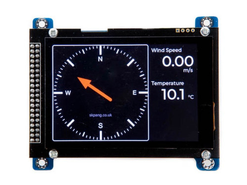
Exploring the Capabilities of the Teensy NMEA 2000 Board with 3.5” Touch LCD
Discover the Teensy 4.0 NMEA 2000 Board with 480x320 3.5” Touch LCD, a high-performance marine electronics solution for real-time data monitoring, navigation, and vessel automation. Perfect for DIY projects and professional applications.
1 note
·
View note
Text
Zwei Temperatursensoren mit Arduino nutzen – so geht’s!

In meinem Beitrag „Arduino-Temperaturüberwachung: Relais per Schwellwert & Tastersteuerung mit LCD-Anzeige“ habe ich gezeigt, wie man mit einem Arduino, einem Temperatursensor und einem LCD-Display eine einfache Temperaturüberwachung realisieren kann. Ein Leser meines Blogs hatte eine großartige Idee zur Erweiterung: Ein zweiter Temperatursensor soll zusätzlich die Außentemperatur auf dem Display anzeigen. https://youtu.be/svC6ph9kCJM Solche Community-Ideen sind immer willkommen, und ich freue mich, wenn meine Projekte weitergedacht und optimiert werden! In diesem Beitrag zeige ich, wie du das bestehende Setup mit einem zweiten Sensor erweiterst, sodass sowohl die Innen- als auch die Außentemperatur angezeigt werden.

Schaltung - Temperaturgesteuertes Relais am Arduino mit zwei DS18B20 Sensoren
Was ist das Ziel?
Das eigentliche Ziel ist die Steuerung eines Relais via Schwellwert mit einem Temperatursensor DS18B20 am Arduino. Wie das funktioniert, habe ich bereits ausführlich im oben verlinkten Beitrag erklärt. In diesem Beitrag geht es nun darum, Arduino zwei Temperatursensoren hinzuzufügen, sodass du sowohl die Innen- als auch die Außentemperatur messen und auf dem Display anzeigen kannst.
Der DS18B20 Sensor im Detail
Zunächst zu den technischen Daten des Sensors: - jeder Sensor hat einen eindeutigen und einmaligen 64Bit Code auf dem onboard ROM - Betriebsspannung – 3.0V bis 5.5V - Messbarer Temperaturbereich von -55 °C bis +125 °C - Toleranz – ±0.5 °C - Auflösung des Thermometers von 9 bis 12Bit

Den DS18B20 Sensor bekommst du als einzelnen Baustein in Form TO-92 oder vergossen in einer wasserdichten Metallkapsel.

verschiedene DS18B20 Sensoren Pinout des Sensors Der Sensor besitzt eine flache sowie eine abgerundete Seite. Wenn wir ihn von oben betrachten, sodass die flache Seite nach vorne zeigt, ergibt sich folgende Pinbelegung (von links nach rechts): - Pin 1 - GND - Pin 2 - DATA - Pin 3 - Vdd / VCC

Pinout - Temperatursensor DS18B20
Erweiterung der Temperaturüberwachung: Umschalten per Taster
Die bestehende Schaltung erweitern wir um einen Temperatursensor und einen Taster. Der Taster dient später zum umschalten zwischen den Ansichten auf dem Display.

Schaltung - zwei DS18B20 LCD-Anzeige und Relais am Arduino
Programmieren der zwei Temperatursensoren in der Arduino IDE
In den nachfolgenden Abschnitten möchte ich dir erläutern wie du den bestehenden Code lauffähig machst (dazu werden ein paar Bibliotheken benötigt) und um einen zweiten Sensor & einen zusätzlichen Taster erweiterst. Benötigte Bibliotheken Bevor wir mit der Programmierung starten können, müssen wir einpaar Bibliotheken für die verwendeten Komponenten installieren - LC-Display > https://docs.arduino.cc/libraries/liquidcrystal-i2c/ - Taster > https://github.com/thomasfredericks/Bounce2 - Temperatursensor DS18B20 > https://github.com/RobTillaart/DS18B20_INT Wie man eine ZIP-Bibliothek in der Arduino IDE installiert, habe ich dir bereits im Beitrag Arduino IDE, Einbinden einer Bibliothek ausführlich erläutert. Die beiden Bibliotheken Bounce2 & DS18B20_INT findest du auch im Bibliotheksverwalter der Arduino IDE und kannst du von dort auch einfach mit einem klick installieren.


Bei der Bibliothek DS18B20_INT musst du zusätzlich die Abhängigkeit OneWire installieren und somit die Schaltfläche "ALLE INSTALLIEREN" wählen. Schritt-für-Schritt Anleitung zum erweitern des Codes für einen zweiten Sensor Nachfolgend die sieben Schritte welche notwendig sind einen zweiten Temperatursensor vom Typ DS18B20 in den Code zu implementieren. Schritt 1 - definieren der Pins für Sensor & Taster Zunächst definieren wir die beiden Pins für jeweils den Sensor und den Taster. //Der zweite Temperatursensor vom Typ DS18B20 ist am //digitalen Pin D6 angeschlossen. #define ds18b20_2 6 //Taster "sensor_select" am digitalen Pin D7 angeschlossen. #define tasterSensorSelect 7 Schritt 2 - Sensor initialisieren Der Sensor DS18B20 verfügt über eine eigene UID und theoretisch kann man die beiden Sensoren auch über einen digitalen Pin verwalten (siehe DS18B20-Sensoren am Raspberry Pi Pico W: Temperaturdaten auf einer Webseite anzeigen) da der Arduino genügend freie Pins hat dupliziere ich hier einfach die beiden Aufrufe. OneWire oneWire2(ds18b20_2); DS18B20_INT sensor2(&oneWire2); Schritt 3 - Feld zum speichern der aktuellen Auswahl Wenn wir den Taster zur Sensorauswahl betätigen möchte ich zwischen diesen beiden wechseln, dazu merke ich mir den Zustand als Zahl im Feld "sensorAuswahl". //Auswahl //0 - Sensor "normal" //1 - Sensor "außen" - nur lesen int sensorAuswahl = 0; Schritt 5 - Taster für Sensorauswahl entprellen Den Taster habe ich wie die anderen auch ohne 10 kOhm PullUp / PullDown Widerstand angeschlossen. Dieses löse ich über den internen 10 kOhm Widerstand welcher mit der MCU verbunden ist. Zusätzlich entprelle ich den Taster über die Bibliothek Bounce2. Bounce btnSensorSelect = Bounce(); void setup(){ ... btnSensorSelect.attach(tasterSensorSelect, INPUT_PULLUP); btnSensorSelect.interval(BTN_INTERVALL); ... } Schritt 6 - Funktion loop erweitern für die Sensorauswahl In der Funktion loop müssen wir nun eine zusätzliche If-Bedingung hinzufügen um auf den Statuswechsel des Tasters zu reagieren und den Wert im Feld "sensorAuswahl" umzukehren. Zusätzlich wird der bisherige Code nur ausgeführt wenn der Wert des Feldes "sensorAuswahl" gleich 0 ist, andernfalls (also wenn dieser 1 ist) wird geprüft ob das Display aktualisiert werden soll und dann der Wert des Außensensors über die Funktion writeLcdDisplay angezeigt. void loop() { ... btnSensorSelect.update(); if (btnSensorSelect.fell()) { sensorAuswahl = sensorAuswahl == 0 ? 1 : 0; writeLcdDisplay(); } if (sensorAuswahl == 0) { ... } else if (sensorAuswahl == 1) { if ((lastUpdate + INTERVALL) //überschreiben des Wertes für die letzte Ausführung lastUpdate = millis(); writeLcdDisplay(); } } Schritt 7 - Funktion writeLcdDisplay erweitern Die Funktion writeLcdDisplay dient dazu die Werte auf dem Display anzuzeigen. Hier müssen wir zusätzlich noch eine If-Bedingung implementieren in welcher wir wieder das Feld "sensorAuswahl" prüfen. Wenn der Außensensor angezeigt werden soll, dann wird in der ersten Zeile der Text "Aussensensor" angezeigt und in der zweiten Zeile der Text "akt. Temp.:" inkl. dem aktuellen Sensorwert. void writeLcdDisplay() { ... if (sensorAuswahl == 0) { ... } else if (sensorAuswahl == 1) { sensor2.requestTemperatures(); printTextAt(0, 0, "Aussensensor"); printTextAt(1, 0, ">akt. Temp.:" + String(sensor2.getTempC(), DEC)); } fertiger Sketch zum anzeigen von zwei Sensorwerten auf einem LC-Display Nachfolgend nun der fertige Sketch zum anzeigen von zwei Sensorwerten am Arduino inkl. Temperatursteuerung. Programm: zwei Temperatursensoren für eine Temperatursteuerung am Arduino UNOHerunterladen Read the full article
0 notes
Text
youtube
This tutorial is a practical demonstration in our series, "How to convert an Arduino PWM signal to an Analog signal (DAC)." In this video, we bring the simulation into a real-world scenario by breadboarding the circuit and porting our Arduino IDE code into the VS Code environment with PlatformIO.
0 notes
Text

Buy 100 RPM 12V DC GEARED MOTOR at Affordable Price in Ainow
100 RPM 12V DC GEARED MOTOR
This 100 RPM 12V DC GEARED MOTOR can be used in all-terrain robots and a variety of robotic applications. These motors have a 3 mm threaded drill hole in the middle of the shaft thus making it simple to connect it to the wheels or any other mechanical assembly. These motors are simple DC Motors featuring gears for the shaft for obtaining the optimal performance characteristics. They are known as Center Shaft DC Geared Motors because their shaft extends through the center of their gearbox assembly. These standard size DC Motors are very easy to use. Also, you don’t have to spend a lot of money to control motors with an Arduino or compatible board. The L298N H-bridge module with an onboard voltage regulator motor driver can be used with this motor that has a voltage of between 5 and 35V DC. Nut and threads on the shaft to easily connect and internally threaded shaft for easily connecting it to the wheels. These 100 RPM 12V DC GEARED MOTOR with robust metal/Plastic gearbox for heavy-duty applications, available in the wide RPM range(Check the list below) and ideally suited for robotics and industrial applications.
#sales in chennai#electronic components#robotic kits#arduino#raspberrypi#sensor#electronics components#adxl335 module price#lcd#5mp camera
1 note
·
View note
Text

DISPLAYS | Buy Online In India
A liquid crystal display (LCD) is a type of display technology that makes use of liquid crystals that open or close when stimulated by an electric current. These liquid crystals are the basis for LCD technology. LCD is considered a major innovation in display devices and is frequently used in mainstream electronics lik
0 notes
Video
youtube
DIY Temperature Controller for Molding Systems | Arduino Tutorial
#youtube#DIY#Arduino Tutorial#Temperature Controller#Molding Systems#Injection Molding#Arduino Nano#Membrane Keypad#LCD#Relay Module#Max6675 Module#Thermocouple#Plastic Molding#Electronics Tutorial#Maker Community#Plastic Injection Molding#Arduino#Hot Nozzle#Molding Process#MAX6675#LCD Display
1 note
·
View note
Video
youtube
GPS Clock Using Raspberry Pi Pico (RP2040) Arm Cortex-M0
#youtube#GPS Clock Using Raspberry Pi Pico (RP2040) Arm Cortex-M0+ & LCD Display | Make a GPS Clock With Arduino - Projects | Arduino GPS Clock | ras
0 notes
Text
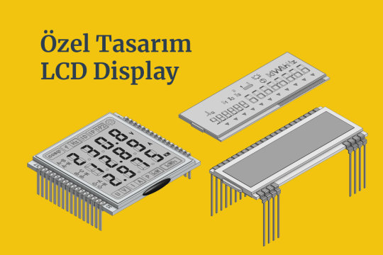
Custom Design LCD Display #lcd #customlcd #display #lcddisplay #lcdmodule #speciallcd #glasslcd #camlcd #backlight #lcdisplay https://www.signal.com.tr/ozel_tasarim_lcd_customized_lcd
#lcddisplay#lcd monitor#lcdmodule#lcdglass#customlcd#display#electronic#engineering#electronicengineering#display technology#screen#lcd#arduino#esp32#esp8266
0 notes
Text

105 notes
·
View notes
Note
heyyyyy vro it’s me skibidiburnerrrr (bro I picked the goofiest username 😭)
I’ve decided I might actually save up for the robotics thing. If I’m on the right track, I should be able to use a dual-display arduino board and use two LCD displays to make eyes. If I add sensors above the eyes, I could try to code them to make the eyes “follow” movement!
I’d use a PVC mask resembling a BJD mask, and I already have a paint color picked out!
.
#the skibidiburnerrrr.......#and THAT IS SO EPICCCCC#self ship#self shipping community#selfshipping community#selfship#self shipper#self shipping#self ship community#selfship community#f/o#f/os#skibidiburnerrrr
8 notes
·
View notes
Text
So I often see novel computer keyboard designs, but I hadn't really felt inspired to make my own until now.
See, Hackaday recently ran a piece on Stephen Holdaway's "Unicode Binary Input Terminal", which lets you flip switches to input any Unicode character — by flipping switches to indicate its binary value in UTF-8 encoding.

It displays the character on the little display, and you can then flip another switch to send the character like a keyboard would over USB.
Among the usual comments about how Holdaway should have built the device by using only 555 timers came the suggestion that UTF-8 is unwieldy, and that he should have added even more toggle switches to enter longer bitstreams directly. Now, I don't want to take that tack on it; toggle switches get expensive. But there are other ways to input long sets of binary data!
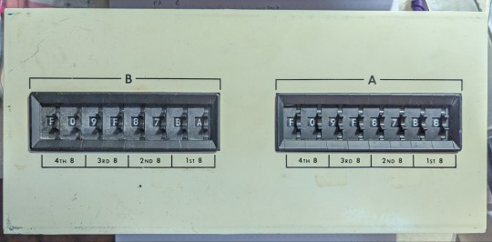
Years ago, I found this panel in some surplus or thrift shop; I honestly don't remember any more. It's got two sets of eight hexadecimal thumbwheel switches; each one can be set to a hexadecimal "digit" between 0 and F, and the binary pattern of that hexit read off the leads in the back.
(If anyone out there recognizes where this panel originally came from, let me know; it has no other markings besides the visible ones, and the switch banks just each bear a sticker saying they came from the Digitran Company of Pasadena, California, and were probably made in 1972. (Remarkably, Digitran still makes very similar switches — I think there's a military spec for them — though they're presently owned by Electro Switch Corp, and are of the sort that don't list prices on the webpage. For similar devices, Surplus Sales of Nebraska has 6-hexit banks, albeit with shorter numbers, available for $225 each, or slightly taller ones for $15 per hexit and you have to fabricate your own frame.)
At any rate, the switch banks are easily removed from the panel. My plan is to set them in a new panel with a display between them and have a toggle or slider switch to change modes, so you can enter UTF-8 streams (anywhere between eight ASCII characters and a single dual-character-point emoji; the wheels are currently set to display the US flag) or sets of UTF-16 or UTF-32 characters; a final button would again send the character(s) over USB.
I'm currently dithering over how best to implement this. Obviously Unicode isn't going to fit in any of my usual microcontrollers, and the 64 data lines required to read the switches will need some GPIO expanders or shift registers. I do have a couple of unused Raspberry Pi ZeroWs lying around, which would let me leverage Linux font and Unicode handling, and then I could hook it to an Arduino or Teensy to handle the USB part, unless there's an obvious way for a Pi to be a USB client. The display is a similar dither; I've got some small graphical LCDs and a tiny OLED display, and even some e-ink displays that might work for this. Heck, I should see if I can find those dot-matrix VFDs I have somewhere. It's more likely to be a color LCD if I want emoji support, but requirements are flexible right now.
25 notes
·
View notes
Text
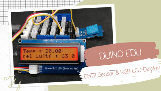
DUINO EDU - DHT11 Sensor & LCD-Display

In diesem neuen Beitrag möchte ich dir gerne zeigen, wie du die Sensorwerte des DHT11 Sensors auf einem LCD-Display per DUINO EDU anzeigen lassen kannst.
Dieses kleine Projekt ist der Wunsch des lesers Sieglinde L. welche das Projekt gerne mit der grafischen Entwicklungsumgebung DUINO EDU umsetzen möchte.
Benötigte Ressourcen für dieses Projekt
Wenn du das kleine Projekt nachbauen möchtest, dann benötigst du: - einen Arduino UNO*, - ein USB-Datenkabel*, - ein Grove Connector Shield / Base Shield v2 für den Arduino UNO*, - ein DHT11 Sensor mit Grove Schnittstelle*, - ein 20x2 Zeichen LCD-Display (I2C) mit Grove Schnittstelle*, - zwei Grove Kabel* Hinweis von mir: Die mit einem Sternchen (*) markierten Links sind Affiliate-Links. Wenn du über diese Links einkaufst, erhalte ich eine kleine Provision, die dazu beiträgt, diesen Blog zu unterstützen. Der Preis für dich bleibt dabei unverändert. Vielen Dank für deine Unterstützung!
Aufbau der Schaltung
Die Schaltung ist mit den Grove Anschlüssen sehr einfach und schnell erledigt, denn das LCD-Display wird lediglich in einen I2C und der DHT11 Sensor in ein digitalen Connector gesteckt.

Schaltung - Grove DHT11 Sensor & LCD-Display am Arduino UNO
DUINO EDU einrichten / konfigurieren
Bevor wir mit der Entwicklung des Programmes starten können, müssen wir die IDE herunterladen. Wie du dieses machst habe ich dir bereits im Beitrag Arduino Programmierung mit DUINO EDU erläutert. Bei der Programmierung ist mir jedoch aufgefallen das der eingestellte Pfad für das standardmäßige Speichern von Projekten zu Problemen führt. Dieser Pfad wird auch genutzt um Bibliotheken zu referenzieren.
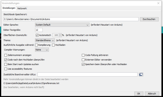
Arduino IDE - Voreinstellungen, Speicherort (default)
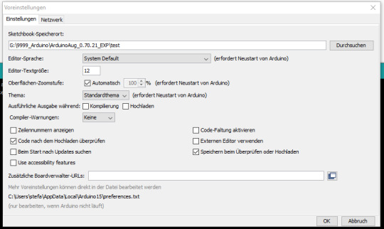
Arduino IDE - Voreinstellungen, Speicherort (custom) Meine Lösung dazu war, den Pfad auf einen anderen Ordner innerhalb der IDE DUINO EDU zu legen.
Programmieren in DUINO EDU
Wenn die Entwicklungsumgebung DUINO EDU fertig eingerichtet ist, dann können wir mit der Programmierung beginnen. Eigentlich ist es keine Programmierung im eigentlichen Sinne denn wir klicken eher per Drag'n Drop GUI Elemente zusammen und daraus wird dann der Code generiert welchen wir auf den Mikrocontroller spielen.

DHT11 Sensordaten am LCD-Display Nachfolgend das YouTube-Video wo ich dir im Detail erläutere wie das Programm aufgebaut wird. https://youtu.be/dJgfNeRQRo8 Fehlende Punkte in der zweiten Zeile In der zweiten Zeile vom LCD-Display werden keine Punkte angezeigt.


Das liegt in diesem Fall an der verwendeten Bibliothek. Wenn man die originale Bibliothek von Seeedstudio in der Arduino IDE verwendet, dann werden alle Zeichen auf dem Display korrekt angezeigt.

Beispiel auf dem RGB LCD-Display mit korrekten Sonderzeichen Das Programm im Detail In der nachfolgenden Grafik zeige ich dir das kleine Programm mit Kommentaren. Du benötigst für das Anzeigen der Sensorwerte auf dem LCD-Display recht wenig GUI Elemente, jedoch werden diese Elemente sehr tief ineinander verschachtelt.
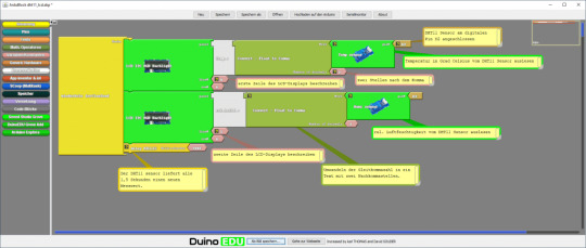
Natürlich kannst du auch den Code etwas lesbarer gestalten und die Werte in Variablen auslagern, jedoch macht dieses den Code nicht viel besser. Den Code kannst du dir auch über nachfolgenden Link als ZIP-Datei herunterladen. Grove DHT11 Sensor & LCD-DisplayHerunterladen
Excurs zum Arduino Code
Schauen wir uns einmal den generierten Code an welcher kompiliert und auf den Mikrocontroller überspielt wird. Zunächst werden die benötigten Bibliotheken importiert. #include #include #include Danach wird geprüft ob das Feld EDU_LCD_ADRESS vorhanden ist, wenn dieses so ist wird eine Bibliothek für das Display importiert, andernfalls wird eine Bibliothek für ein RGB LCD-Display importiert. #if defined (EDU_LCD_ADRESS) #include Duinoedu_LiquidCrystalUp monRgb(EDU_LCD_ADRESS, EDU_LCD_COLS, EDU_LCD_ROWS); #else rgb_lcd monRgb; #endif Im nächsten Schritt wird eine Instanz des DHT Sensor objektes initialisiert mit der zusätzlichen Information das am digitalen Pin D2 ein Sensor angeschlossen ist. DHT monDHT_pin2(2); In der Funktion setup wird das Display und die Kommunikation mit dem Sensor gestartet. void setup(){ monRgb.branch(); monDHT_pin2.brancher(); } Die Funktion loop wird fortlaufend ausgeführt und liest und schreibt die Sensordaten auf das Display. Die Funktionen dabei sind in französischer Sprache (warum auch immer). void loop(){ monRgb.placerCurseurEn(0,0); monRgb.ecrire("Temp.:" ); monRgb.ecrire(String(monDHT_pin2.lireTemperature(),2) ); monRgb.placerCurseurEn(1,0); monRgb.ecrire("rel.Luftf.:" ); monRgb.ecrire(String(monDHT_pin2.lireHumidite(),2) ); delay( 2000 ); } Hier nun der komplette Code: #include #include #include #if defined (EDU_LCD_ADRESS) #include Duinoedu_LiquidCrystalUp monRgb(EDU_LCD_ADRESS, EDU_LCD_COLS, EDU_LCD_ROWS); #else rgb_lcd monRgb; #endif DHT monDHT_pin2(2); void setup() { monRgb.branch(); monDHT_pin2.brancher(); } void loop() { monRgb.placerCurseurEn(0,0); monRgb.ecrire("Temp.:" ); monRgb.ecrire(String(monDHT_pin2.lireTemperature(),2) ); monRgb.placerCurseurEn(1,0); monRgb.ecrire("rel.Luftf.:" ); monRgb.ecrire(String(monDHT_pin2.lireHumidite(),2) ); delay( 2000 ); } Read the full article
0 notes
Text
Top 10 Projects for BE Electrical Engineering Students
Embarking on a Bachelor of Engineering (BE) in Electrical Engineering opens up a world of innovation and creativity. One of the best ways to apply theoretical knowledge is through practical projects that not only enhance your skills but also boost your resume. Here are the top 10 projects for BE Electrical Engineering students, designed to challenge you and showcase your talents.
1. Smart Home Automation System
Overview: Develop a system that allows users to control home appliances remotely using a smartphone app or voice commands.
Key Components:
Microcontroller (Arduino or Raspberry Pi)
Wi-Fi or Bluetooth module
Sensors (temperature, motion, light)
Learning Outcome: Understand IoT concepts and the integration of hardware and software.
2. Solar Power Generation System
Overview: Create a solar panel system that converts sunlight into electricity, suitable for powering small devices or homes.
Key Components:
Solar panels
Charge controller
Inverter
Battery storage
Learning Outcome: Gain insights into renewable energy sources and energy conversion.
3. Automated Irrigation System
Overview: Design a system that automates the watering of plants based on soil moisture levels.
Key Components:
Soil moisture sensor
Water pump
Microcontroller
Relay module
Learning Outcome: Learn about sensor integration and automation in agriculture.
4. Electric Vehicle Charging Station
Overview: Build a prototype for an electric vehicle (EV) charging station that monitors and controls charging processes.
Key Components:
Power electronics (rectifier, inverter)
Microcontroller
LCD display
Safety features (fuses, circuit breakers)
Learning Outcome: Explore the fundamentals of electric vehicles and charging technologies.
5. Gesture-Controlled Robot
Overview: Develop a robot that can be controlled using hand gestures via sensors or cameras.
Key Components:
Microcontroller (Arduino)
Motors and wheels
Ultrasonic or infrared sensors
Gesture recognition module
Learning Outcome: Understand robotics, programming, and sensor technologies.
6. Power Factor Correction System
Overview: Create a system that improves the power factor in electrical circuits to enhance efficiency.
Key Components:
Capacitors
Microcontroller
Current and voltage sensors
Relay for switching
Learning Outcome: Learn about power quality and its importance in electrical systems.
7. Wireless Power Transmission
Overview: Experiment with transmitting power wirelessly over short distances.
Key Components:
Resonant inductive coupling setup
Power source
Load (LED, small motor)
Learning Outcome: Explore concepts of electromagnetic fields and energy transfer.
8. Voice-Controlled Home Assistant
Overview: Build a home assistant that can respond to voice commands to control devices or provide information.
Key Components:
Microcontroller (Raspberry Pi preferred)
Voice recognition module
Wi-Fi module
Connected devices (lights, speakers)
Learning Outcome: Gain experience in natural language processing and AI integration.
9. Traffic Light Control System Using Microcontroller
Overview: Design a smart traffic light system that optimizes traffic flow based on real-time data.
Key Components:
Microcontroller (Arduino)
LED lights
Sensors (for vehicle detection)
Timer module
Learning Outcome: Understand traffic management systems and embedded programming.
10. Data Acquisition System
Overview: Develop a system that collects and analyzes data from various sensors (temperature, humidity, etc.).
Key Components:
Microcontroller (Arduino or Raspberry Pi)
Multiple sensors
Data logging software
Display (LCD or web interface)
Learning Outcome: Learn about data collection, processing, and analysis.
Conclusion
Engaging in these projects not only enhances your practical skills but also reinforces your theoretical knowledge. Whether you aim to develop sustainable technologies, innovate in robotics, or contribute to smart cities, these projects can serve as stepping stones in your journey as an electrical engineer. Choose a project that aligns with your interests, and don’t hesitate to seek guidance from your professors and peers. Happy engineering!
5 notes
·
View notes