#Dual switching diode
Explore tagged Tumblr posts
Visit Tumblr Blog
Explore Tumblr blogs with no restrictions, modern design and the best experience.
Last Seen Tumblr Blogs


Fun Fact
In 2020, 27% of US Tumblr users had an annual household income of over $100,000.
Text
Reverse voltage, Dual switching diode, switching times, Solid State Switches
1N4148W Series 2 A 100 V 400 mW Surface Mount Fast Switching Diode - SOD-123
0 notes
Text
https://www.futureelectronics.com/p/semiconductors--discretes--diodes--switching/sbav99lt1g-onsemi-8159990
High speed switching diode, diode switching times, diode switching times
BAV99 Series 70 V 715 mA Surface Mount High Speed Switching Diode - SOT-23
#onsemi#BAV99LT1G#Diodes#Switching Diodes#High speed#diode switching times#pin diode switch#Dual#switching diode vs Zener diode#reverse voltage#Solid State Switches#switching operation
1 note
·
View note
Text
https://www.futureelectronics.com/p/semiconductors--discretes--diodes--switching/1n4148wq-7-f-diodes-incorporated-7037709
Diodes Incorporated, 1N4148WQ-7-F, Diodes, Switching Diodes
1N4148W Series 400 mW 100 V 300 mA SMT Switching Diode - SOD-123
#Diodes Incorporated#1N4148WQ-7-F#Diodes#Switching Diodes#Dual#application#radiofrequency#RF switches#ultra high speed#Pin diode switch#signal switching diode#Switching Diode#what is a switching diode#Diode switch
1 note
·
View note
Text
https://www.futureelectronics.com/p/semiconductors--discretes--diodes--switching/1n4148w-7-f-diodes-incorporated-7634694
Diodes, Switching Diodes, 1N4148W-7-F, Diodes Incorporated
1N4148W Series 2 A 100 V 400 mW Surface Mount Fast Switching Diode - SOD-123
#Diodes#Switching Diodes#1N4148W-7-F#Diodes Incorporated#High speed switching applications#reverse voltage#module#Power management circuits#diode switch#High Speed Diode#Microwave diode#Dual
1 note
·
View note
Text

Finally got my Eurorack system updated on ModularGrid — I hadn't gotten around to setting up a few of my custom modules, like the Harald Bluetooth Receiver, the Toy Drum, my true diode Ring Modulator, and my analog logic module "Lola".
Starting with the top left is the Behringer Radar, a contact mic and input amplifier with a gate and a triggered envelope. It's a version of the Mutable Instruments Ears (itself an adaptation of the MTM Mikrophonie); the big change is that all the sensitivity and envelope jumpers are brought out to front panel switches.
Next is one of North Coast Synthesis's "Passive Multiples and Friends", which I built as a mult.
Next is the Behringer Model 182, a clone of the Roland Model 100-series analog sequencer. (A Christmas gift from my wife's parents!)
Next is the MidCentury Modular Dividers, which combines a binary clock divider (simultaneous ÷2 - ÷128) and an adjustable (÷2 - ÷9) divider, both based on CMOS chips. (Built from a PCB/panel set).
Next is my homebrew analog logic module Lola. It has two sections: the unary input which takes one signal and outputs its inverse and its half- and full-wave rectified versions, and the binary input which gives you the OR, AND, and XOR of two signals. (Lola is named that because it's mostly based on the Mutable Instruments module "Kinks". I left off its S&H and added the XOR.)
Next is Chaos, a clone of the MI Marbles random gate and voltage generator.
Next is a set of two low-pass gates, made from vactrols, which I built onto a buggy (malformed) version of my oscilloscope module panel.
Next is my LittleBits Adapter, which lets me plug in the magnet-based circuit building toy modules including those from the Korg collab.
On the second row, we start with the Behringer Model 150, another Roland 100 series clone; this one is noise, a S&H, a ring mod (actually a chip based four quadrant multiplier), and an LFO.
Next looks like another Passive Multiples and Friends, but this one is my Simple Cascading Fixed Amplifier, a set of four fixed amplifiers set up to do x2, x10, or x20 without modifications and up to x400 with self-patching.
The next is a Passive Multiples and Friends, this one an OR Combiner meant to combine multiple gate or trigger signals.
Next is the Kassutronics VCO 3340, an analog VCO I built from the PCB/panel set — basically the CEM3340 chip broken out plus a sine wave output (though the chip is actually the AS3340 clone).
After that is the 3320-VCF by PM Foundations, a low-pass filter with voltage-controlled cutoff and resonance, again built from PCB/panel.
Then it's my first VoxMachina Sigma function/slew generator, followed by a dual attenuverter/mixer, followed by the second Sigma — all together basically a workalike of the Make Noise Maths. The Sigma is very versatile but mostly ends up used for envelopes and LFOs. I had the pcbs and panels fabricated from VoxMachina's uploaded Gerber files.
Next is another Passive Multiple.
The next is a Behringer Four Play, four VCAs that can be used separately or mixed together. It's a functional rip-off of, I believe, Intellijel's quad VCA design.
Next is my homemade ring modulator, a proper two-transformers-and-a-diode-ring unpowered design.
After that, built into another PMaF panel, are two copies of the IamO single-JFET VCA, followed by my version of David Haillant's Simple VCA.
And last in the center row is the Modular in a Week "A Simple Mixer, Right?" (ASMR). A basic five-channel mixer with plain and inverted outputs, I got this as a kit.
In the third row, we start with MiaW's POW, which has LEDs for each power rail, a USB power jack, an external Eurorack power breakout, and a switch that currently doesn't do anything. (I'm still debating whether I should add case lighting.)
Next is a very simple reverse-avalanche oscillator with (not particularly tracking) voltage control, built from LMNC schematics.
Next is the Behringer Brains, their adaptation of the MI Plaits; it's a tremendously versatile voice that's way too tempting to leave on speech synthesis mode.
After that is another Simple Cascading Fixed Amplifier. I think this one uses inverting amplifiers and the other uses non inverting ones?
Next is the Toy Drum — I tore apart one of those electronic drum kits with the roll-up rubber pads and wired up inputs to four of the triggers, giving me a cheap but cheerful kick, snare, hat, and cymbal set.
Next is the Harald Bluetooth Receiver, the module out of a DIY Bluetooth speaker; it'll play stuff off a paired phone, or read files from a microSD card or USB stick.
Next is the DSPFX, a very cheap 100-in-1 audio effects board, which I often use to add end-of-chain reverb/delay and stereo separation. Built from MiaW design, though I had the panel fabricated.
The final PMaF is wired in passive mixer mode; it usually combines the ASMR mixer's output with the stereo output from the DSPFX, the two channels feeding the Phonic, my custom headphones output device (based on the circuit from the Befaco Out).
That's a total of 6 purchased modules, 2 kit builds, 3 PCB/panel builds, 5 PMaF panel builds, 2 fabs from Gerbers, and 13 modules of assorted more custom building, all in a homemade case. Not too shabby, I guess.
2 notes
·
View notes
Text
DIY Dumble-like sounding MOSFET Overdrive

The Hermida Zendrive guitar pedal we will study, assemble and listen to today is a true masterpiece. Many say its sound is close to the Holy Grail of guitar amplification - Dumble Overdrive Special.
Other people are more pessimistic in their judgments. Still, the precise response to the picking dynamics, the Voicing tuning options, and the sheer beauty of this overdrive's sound are simply impossible not to love.
But before we study the Lovepedal Zendrive or its copy of the Landtone Phoenix song, or the Aion effects Azimuth dynamic overdrive, we'll study the evolution of the MOSFET overdrives that finally resulted in the development of this gem.
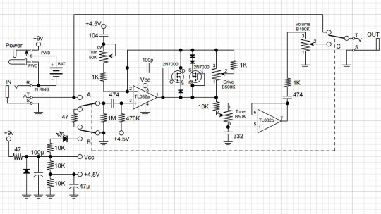
Fulltone OCD

Mike Fuller was one of the first to start using MOSFETs instead of diodes to limit the amplified guitar signal in 2004.
His Obsessive-Compulsive Drive overdrive-distortion pedal is built on a standard circuit with one dual op amp. The first operational amplifier, X1, amplifies the amplitude of the guitar signal by a factor from 8 to 463 times, depending on the position of the drive control X3. This is a 1-megohm potentiometer.

Further, through resistor R9, the signal is fed to the limiter, which comprises 2N7000 MOSFETs M1 and M2 connected in parallel. A germanium diode D1 - 1N34A is additionally included in series with M2, which makes the limiter asymmetrical and, therefore, makes more interesting sound.
A limiter in overdrives is usually included in the negative feedback circuit of an operational amplifier (i.e., in parallel with C6). Such a limiter is called a soft limiter.
And here, a hard limitation is applied: clipping sections are included between the preamplifier output of the gain section and the virtual ground - half of the supply voltage Vref, formed by resistors R4 and R7.
Virtual ground is used in the unipolar powering of operational amplifiers to amplify analog signals, such as audio signals. The guitar signal does not change from zero to plus but from minus to plus, passing through zero.
To prevent the signal from being limited to the circuit's ground, it is shifted in the plus direction by half the supply voltage.
Such hard limiting is typical for distortion pedals. But by using MOSFETs instead of diodes or LEDs, the top of the signal is not cut hard but softly rounded. Therefore, OCD can work as both distortion and overdrive.
Due to the smoothed peaks of the limited signal, the sound is highly dependent on the sound's attack dynamics. For rock and especially blues, this is very valuable. With modern metal pickups that compress the dynamic range of the signal, it can help make solos sounding more sweet.
The second operational amplifier X3 amplifies the limited signal by a factor of 3.8, correcting its timbre. Capacitors C6 and C9 prevent the self-excitation of operational amplifiers at high frequencies.
Next is a simple passive tone knob, which implies a treble leak circuit. Potentiometer X4 10 kilohms and capacitor C11 47 nanofarads are connected in the same way as on the pickguard of any electric guitar.
The Switch1 switch changes the circuit's output impedance as if the high-impedance and low-impedance pickups were switched. When it's open, you get a transparent overdrive like the Klon Centaur, and when it's closed, you can get a more aggressive sound like the Marshall Plexi.
Hermida Audio Zendrive

The Zendrive pedal's authors, Hermida audio technology (now produced by LOVEPEDAL LLC), have undoubtedly studied the Fulltone OCD thoroughly. Let's find the differences between the two circuits.
First, the limiter is included in the operational amplifier feedback, that is, between the output and the inverting input, not between the output and virtual ground. That is, here we have a soft limiter.
Secondly, one diode is added in series with each MOSFET. Clipping remains asymmetric: we have one diode in the left arm of the limiter and two diodes in the right arm.
Third, the second operational amplifier is used as a voltage repeater, aka buffer: the output is directly connected to the inverting input.
Fourth, the tone control is implemented a little differently: two OCD`s switchable resistors are replaced by a potentiometer.
And finally, the most critical, fifth difference. A potentiometer is included in the tone correction circuit between the inverting input of the first operational amplifier and the artificial midpoint.
This fourth knob, Voicing, or Character, allows you to smoothly adjust the lower frequencies in the overdrive structure over a wide range, similar to the Resonance control on many tube guitar amps.
The potentiometer is signed as a trimmer in the diagram because some pedal makers don't want to install a fourth knob on the pedal`s body. This is what Landtone did when developing the Phoenix Song Overdrive DIY kit.
The developer suggests installing the trimmer on the PCB, and to access it, you need to disassemble the pedal by unscrewing the footswitch nut and taking out the PCB.
But I will not be lazy to drill an extra hole in the pedal body and install a potentiometer with a knob, connected to PCB by wires instead of the trimmer. Because I consider this regulator simply invaluable and irreplaceable.
Before we get to assembly and testing, let's look at another pedal with a similar adjustment. However, it is based not on the Fulltone OCD but on the Ibanez Tube Screamer.
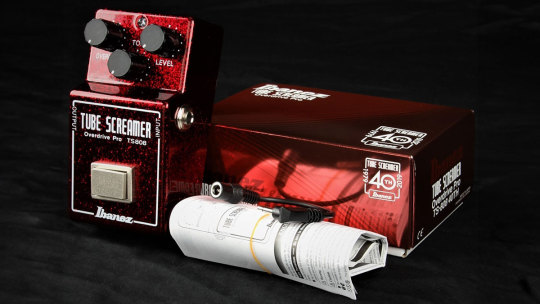
The Precision Drive

This is a signature pedal by Misha Mansour of Periphery, manufactured by Horizon Devices. Compared to the original Overdrive Pro TS808, the circuit adds a noise suppressor, which we will not consider, and an exciting ATTACK switch.
The Precision Drive scheme was studied and partially replicated by PedalPCB and PCB Guitar Mania. They are manufacturers of DIY kits for guitarists. Their products are called Dwarven Hammer and Collision Drive, respectively. A noise gate is not provided there, but the attack switch is implemented. This is the main difference between Precision Drive and many other overdrive pedals.
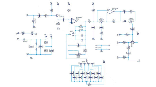
In the Fulltone OCD schematic, we saw a resistor switch at the tone shaping circuit in the output section. The Zendrive has a variable resistor in the preamp's RC circuit which is controlling the overdrive structure.
Precision Drive has a constant resistor in the same place, between the inverting input of the overdrive section operational amplifier and the virtual ground, but the capacitors are switched.
This is the same thing: we change the time constant of the RC circuit, which adjusts the audio signal's frequency spectrum. At the same time as the time constant, the complex impedance changes, thus the gain.
A resistor is a resistance to both DC and AC current. At the same time, a capacitor is only resistant to AC current because DC current does not flow through a capacitor. Since DC current does not flow through our RC circuit, there is no difference between adjusting the resistance and switching the capacitance.
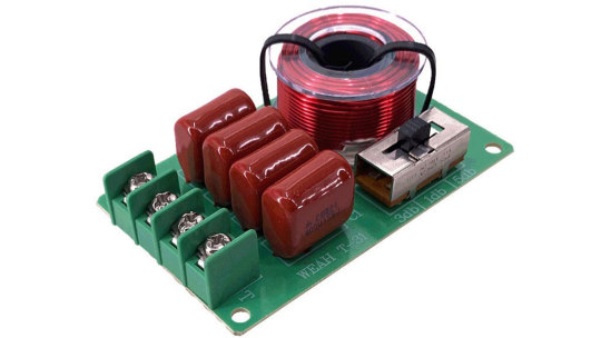
But the active/reactive ratio affects the circuit's Quality factor, i.e., its resonance. It's no coincidence that the knob on guitar amplifiers, which adjusts the same frequencies as our potentiometer or switch, is often called RESONANCE. And it is used to adjust to the resonance of the electromechanical system - the loudspeakers in the cabinet, along with the masses of air in and around it.
The reactive impedance accumulates energy and gives it away, except for losses due to dielectric recharging and magnetizing the magnetic core in inductors. This is why coreless inductors are often used in high-end equipment, so-called air inductors. They weigh a lot, take up a lot of space, and are expensive because copper is more expensive than steel. But these are the laws of physics on which technology is based.
Unlike reactive impedance, active resistance converts electrical energy into heat, thus reducing the Q-factor. In some cases, it is necessary and useful. In others, it is harmful. Or it simply creates a unique sound character.
That's why switching capacitors and turning the potentiometer knob in the feedback circuit of an audio frequency amplifier is almost the same thing, but not quite. And it's great that there are such different variants of guitar overdrive pedals!
Landtone Phoenix Song Overdrive
Now you can hear how my Zendrive from the Landtone OD-1 kit sounds, with a Seymour-Duncan SH4 humbucker on a Gibson MM Explorer guitar, into an Orange MT20 with a Torpedo Captor X. And see how I assembled the pedal and also a kitten walking around the table and prancing around.
youtube
I liked the pedal, especially its fourth magic Voicing knob, which does things to the sound that other tone controls can't. I also liked the bird on the body. Because I love birds. And in the music world, the decoration of instruments and hardware plays no small role because it inspires creativity. And the fact that the pedal is assembled by my hands also warms my soul and creates inspiration.
3 notes
·
View notes
Text
N+N > 2N? The Superposition Buff of MOS Transistors
Dual-N+N means that a semiconductor device or circuit contains two N-type semiconductor-related circuit structures. For example, a dual N-type transistor combination circuit, also known as a dual N+N channel MOSFET.
So, why connect two NMOS transistors together? How do they work?

Complementary Switches: Two NMOS transistors can be used to build a complementary switch circuit, where one NMOS is responsible for connecting the power supply (VDD) to the load, and the other connects the load to ground.
Usage Scenarios of Dual NMOS: There are two configurations: series and parallel.

Series Configuration: When two NMOS transistors are connected in series, they are typically used to control higher voltage circuits. For example, one NMOS controls the signal (from low to high voltage), while the other is used to drive the load of the high-voltage circuit.

Why use two MOS transistors in series? When using a single MOS transistor, when the MOS is turned off, the body diode of the MOS still allows discharge from the battery, so the off-state doesn’t fully isolate the circuit.
However, when using two MOS transistors in series, both can be turned off. Due to the reverse body diode connection, it effectively blocks the battery discharge.

Parallel Configuration: This configuration can be used to increase the switching conductivity. When two NMOS transistors are connected in parallel, the current can flow through any NMOS that is turned on.

Advantages of Dual NMOS:
High Conductivity: The carriers in NMOS transistors are electrons, which have a high mobility. So, does connecting two NMOS transistors together effectively enhance the advantages of a single NMOS? The answer is yes. Because of the higher electron density in dual N-type MOS transistors, they offer lower on-resistance, which helps to improve conductivity efficiency.

Radiation Resistance: The structure of dual N-type MOS transistors usually provides better radiation resistance, allowing them to operate in harsh environments.
Low Power Consumption: The switching characteristics of dual N-type MOS transistors allow them to operate at lower drive voltages, reducing power consumption. This makes them especially suitable for low-power electronic devices.
It is worth mentioning that due to these advantages, dual NMOS combinations are widely used in applications such as home appliances, LED technology, and more.
0 notes
Text
Made you look!
I can't help it. I keep checking the local ads for treasure. Our used equipment emporium has an interesting batch of amplifiers today. There are a couple of Brystons, a Classic Crown D300, and a big Pioneer. There is also a rare bird which is a PS Audio 200CX.
That is a 1990s 200 Watt / ch amp from an interesting company. They are pretty big now, but back then PS was still trying to make a name. That means they tried harder and charged less.
This one is a full complementary transistor amp. In the day Stereophile Magazine raved about it. It was better than most big Tube amps. Not the best though! I had to check it out. What did they do differently?
There are several things they tried. First it is dual mono in the power supply. There are two separate sets of diode bridges and big capacitors with small film capacitors added to suppress RF and switching noise. Second they built heavy solid copper buss bars for ground and main power to deliver to the output transistors. Third they made the signal path direct coupled which means no capacitors in the signal path. All these things are basic robustness. You want current, we got current.
There is also a brag about making the output transistors from copper to dissipate heat and such. I think most metal transistor cases are copper, but plated, as copper corrodes in air. Hell aluminum would be fine too I think, but whatever. They also have a boutique touch as the fuse holders and fuse ends are gold plated. That is not a bad idea, but totally boutique, and how to get replacements?
The circuit is pretty conventional with all bipolar semiconductors but for a pair of FETs in the input. (Laser Trimmed with the finest lasers!) They claim low distortion with only a bit of feedback for stability. Carefully made and crafted from the finest parts.
The fundamental solid state amp circuit was developed in the 1960s. Better parts and more care in design is all that is really different. The result here is a beast that made the golden ears sit up and take notice. Solid and well built.
I admit being attracted to these attention to detail things. They are the kind of thing I would do, and to a small degree have done. No room in the franken-amp for solid copper buss bars though. I suspect it is a bit better than the Franken-amp. We are talking tiny increments though. I mean lips parting is one thing, but do I need to count the teeth behind the lips?
They want an affordable price of $800 bucks for it. The store has an excellent service department, so everything gets checked out. I could probably sell the old tubes from my ARC amp for half that. Hmmm.
Silly thoughts. These will pass in time. Its winter still and the ARC space heater is in the rack. It sounds fine, and actually is a bit newer.
1 note
·
View note
Text
Laser Processing Market Key Companies and Emerging Trends, 2030
The global laser processing market size was valued at USD 17.48 billion in 2021 and is expected to expand at a compound annual growth rate (CAGR) of 9.1% from 2022 to 2030.
The market growth is attributed to the increased usage of lasers in medical devices and surgery applications. In addition, the rapid growth of nano-fabrication technology is expected to contribute to the growth of the global market. Furthermore, the manufacturing sector has increased the adoption of laser technology for processing the material due to many advantages over traditional material processing, which is expected to be one of the major factors driving the market.
For example, the traditional manual metal arc welding method is used to cause high potential environmental impacts. This was a hot issue that was solved by adopting laser technology in the car industry. For instance, in July 2021, Furukawa Electric launched an Industrial fiber laser. This machine has a 12kw fiber laser system used to weld the car bodies and their parts, including the aluminum process, battery welding, and motors.
Gather more insights about the market drivers, restrains and growth of the Laser Processing Market
Detailed Segmentation:
Product Insights
The gas segment dominated the market with a revenue share of more than 55.0% in 2021. The gas segment entails copper, nitrogen, carbon dioxide, carbon monoxide, argon-ion, and helium-neon lasers. The solid-state segment is further categorized as Q-switched Nd: YAG lasers, small diode-pumped Nd: YAG or Nd: YVO4 lasers, and larger lasers in side-pumped or end-pumped configurations. The usage of fiber lasers facilitates manufacturers to exploit the benefits of this technology in their manufacturing processes.
Process Insights
The material processing segment dominated the market with a revenue share of over 70.0% in 2021. This section includes all the major aspects of laser and material processing, including hybrid processes, development, and implementation of laser beam welding, micro-drilling, surface modifications, cutting and machining, direct manufacturing and forming micro deposition, and ablation of bulk material and coatings.
Application Insights
The machine tools segment led the market with a revenue share of over 30.0% in 2021. The increasing adoption of lasers in the industrial sector for various material processing applications, such as cutting, welding, drilling, and engraving, is projected to drive the machine tools application segment. The surging demand in microelectronics and the medical sector is anticipated to spur growth in the global laser processing industry. Welding plays a significant role in the production of medical devices. Key medical applications include pacemakers, implantable devices, and surgical tools, which need ultra-fine wires and non-porous and sterile surfaces utilized in cardiac procedures.
Regional Insights
Asia Pacific led the market with a revenue share of over 40.0% in 2021. It is expected to witness substantial growth owing to the rising number of OEMs in this region. Furthermore, China is anticipated to arise as the key consumer of industrial lasers and systems for materials processing and micro-processing. Countries such as India, South Korea, Japan, and China are expected to witness high growth owing to numerous factors such as an upsurge in the number of OEMs and automobile industry growth.
Browse through Grand View Research's Electronic Devices Industry Research Reports.
• The global LED modular display market was valued at USD 7.53 billion in 2023 and is projected to grow at a compound annual growth rate (CAGR) of 13.7% from 2024 to 2030.
• The global dual screen laptops market size was valued at USD 2.65 billion in 2023 and is projected to grow at a compound annual growth rate (CAGR) of 3.6% from 2024 to 2030.
Key Companies & Market Share Insights
The market is characterized by intense competition with the presence of a few major global players holding a significant market share. Key players emphasize new product developments to offer avenues for increased profitability through better customer relationships. Companies such as Universal Laser Systems offer products for security agencies and military branches for asset management, custom parts fabrication, and other production and security uses. These systems are also used on airfields, military bases, and naval vessels across the globe.
Some prominent players in the global laser processing market include:
• Altec GmbH
• Alpha Nov laser
• Amada Co., Ltd.
• Bystronic Laser AG
• Epilog Laser, Inc.
• Eurolaser GmbH
• Han's Laser Technology Industry Group Co., Ltd.
• IPG Photonics Corporation
• Newport Corporation (MKS Instruments, Inc.)
• LaserStar Technologies Corporation
• Coherent Inc.
• IPG Photonics Corporation
• Newport Corporation
• Trumpf GmbH + Co. KG
• Universal Laser Systems, Inc.
• Xenetech Global Inc.
Laser Processing Market Segmentation
Grand View Research has segmented the global laser processing market report based on product, process, application, and region:
• Product Outlook (Revenue, USD Million, 2017 - 2030)
• Gas
• Solid-state
• Fiber
• Others
• Process Outlook (Revenue, USD Million, 2017 - 2030)
• Material Processing
• Marking and Engraving
• Micro-Processing
• Application Outlook (Revenue, USD Million, 2017 - 2030)
• Automotive
• Aerospace
• Machine Tools
• Electronics and Microelectronics
• Medical
• Packaging
• Regional Outlook (Revenue, USD Million, 2017 - 2030)
• North America
o U.S.
o Canada
• Europe
o Germany
o U.K.
o France
• Asia Pacific
o China
o India
o Japan
• Latin America
o Brazil
o Mexico
• Middle East & Africa (MEA)
Order a free sample PDF of the Laser Processing Market Intelligence Study, published by Grand View Research.
#Laser Processing Market#Laser Processing Market size#Laser Processing Market share#Laser Processing Market analysis#Laser Processing Industry
0 notes
Text
Semiconductor Parts in the Aircraft Industry: Enhancing Safety and Efficiency
In the fast-paced world of aviation, where precision, reliability, and safety are paramount, the role of semiconductor components cannot be overstated. These tiny yet powerful devices form the backbone of modern aircraft systems, enabling critical functions that ensure smooth operations from takeoff to landing. Let’s explore some key semiconductor parts and their contributions to the aerospace industry.
Diodes: Directing Current Flow with Precision
Diodes are fundamental semiconductor components in aircraft systems. They primarily serve to control the direction of electric current, ensuring that electricity flows in only one direction. In aviation, diodes are used in various applications such as power supplies, switching circuits, and voltage regulation. They play a crucial role in protecting sensitive electronic equipment from reverse voltage spikes and ensuring stable operation of essential systems.
Triacs: Controlling AC Power
Triacs are semiconductor devices that enable the precise control of AC (alternating current) power. They are extensively used in aircraft for applications such as dimming lights, controlling heating elements, and managing motor speed. Triacs allow for efficient and reliable adjustment of power levels, contributing to energy savings and operational flexibility in onboard systems.
Transistors: Switching and Amplification
Transistors are perhaps the most versatile semiconductor devices found in aircraft electronics. They serve dual roles as switches and amplifiers, crucial for controlling signals and power in avionics systems. Transistors enable efficient switching of digital signals, amplification of weak signals from sensors, and modulation of radio frequencies in communication systems. Their reliability and performance under varying environmental conditions make them indispensable in aerospace applications.
Bridge Rectifiers: Converting AC to DC
Bridge rectifiers are semiconductor assemblies used to convert alternating current (AC) into direct current (DC). In aircraft, where numerous systems and equipment rely on DC power, bridge rectifiers play a critical role in converting power from generators and other AC sources into a usable form. They ensure a steady and reliable supply of DC voltage for avionics, navigation instruments, communication devices, and other essential onboard systems.
SCRs (Silicon-Controlled Rectifiers): Ensuring Power Regulation
SCRs are semiconductor devices used for precise control of large electrical currents. They excel in applications requiring high current regulation and are commonly found in aircraft power management systems. SCRs ensure efficient power distribution, voltage regulation, and protection against overcurrent conditions. Their robust design and ability to handle high-power loads make them essential for maintaining the reliability and safety of critical aircraft systems.
Challenges and Innovations in Semiconductor Technology
The aerospace industry poses unique challenges for semiconductor technology. Aircraft operate in extreme environmental conditions, including wide temperature ranges, high altitude, and electromagnetic interference. Semiconductor manufacturers continually innovate to develop components that meet stringent aerospace standards for reliability, durability, and performance under such demanding conditions.
Advanced materials and manufacturing techniques are key to producing semiconductor parts capable of withstanding the rigors of flight. Specialized coatings, ruggedized designs, and enhanced thermal management techniques ensure that semiconductor devices maintain optimal performance throughout their operational lifespan.
Future Directions and Beyond
Looking forward, semiconductor technology will continue to drive innovation in the aerospace industry. Advancements in materials science, miniaturization, and integration will enable more compact and energy-efficient aircraft systems. The ongoing development of smart sensors, artificial intelligence, and connectivity solutions will further enhance aircraft performance, safety, and passenger comfort.
In conclusion, semiconductor components are integral to the evolution of aviation technology, enabling aircraft to operate more efficiently, safely, and reliably. As aerospace engineering continues to push boundaries, semiconductor innovation will play a central role in shaping the future of air travel, ensuring that aircraft remain at the forefront of technological advancement in the 21st century and beyond.
#semiconductors#aircraft parts#aviation industry#aerospace#aviation parts#aerospace industry#industrial parts supplier
1 note
·
View note
Text
https://www.futureelectronics.com/p/semiconductors--discretes--transistors--mosfets/dmg1026uv-7-diodes-incorporated-2129543
MOSFET as a switch, n-channel mosfet, mosfet amplifier
Dual N-Channel 60 V 2.1 Ohm 0.45 pC 0.65 W Silicon SMT Mosfet - SOT-563
#Transistors#Mosfets#DMG1026UV-7#Diodes Incorporated#MOSFET as a switch#n-channel mosfet#mosfet amplifier#Transistor mosfet#high power mosfet#mosfet switch#load switch mosfet#High voltage mosfet#mosfet gate
1 note
·
View note
Text
https://www.futureelectronics.com/p/semiconductors--discretes--transistors--mosfets/dmg1026uv-7-diodes-incorporated-5048908
Transistor mosfet, mosfet switch, mosfet module, types of mosfet, mosfet gate
Dual N-Channel 60 V 2.1 Ohm 0.45 pC 0.65 W Silicon SMT Mosfet - SOT-563
#Diodes Incorporated#DMG1026UV-7#Transistors#Mosfets#mosfet switch#mosfet module#types of mosfet#mosfet gate#circuits#mosfet amplifier#Silicon#Mosfet vs transistor#mosfet uses#how mosfet works#mosfet transistor
1 note
·
View note
Text
Energy-Efficient Fixtures for a Green Bathroom Renovation
In today's environmentally conscious world, more homeowners are opting for green solutions when renovating their bathrooms. Energy-efficient fixtures not only help reduce your carbon footprint but also lower utility bills in the long run. If you're planning a bathroom renovation in Whitby, Altima Kitchens and Closets Inc. is your trusted partner for incorporating sustainable practices into your project. Let's explore how energy-efficient fixtures can transform your bathroom into an eco-friendly oasis.
1. Low-Flow Toilets
One of the most impactful upgrades you can make during a bathroom renovation is installing a low-flow toilet. Traditional toilets can use up to 1.6 gallons (6 liters) of water per flush, whereas low-flow toilets use significantly less—often as little as 1.28 gallons (4.8 liters) per flush or even less with dual-flush models. This reduction in water usage not only conserves water but also lowers your water bill over time.
Altima Kitchens and Closets Inc. offers a range of stylish low-flow toilets that meet water efficiency standards without compromising on performance or design for your bathroom renovation in Whitby.
2. Water-Efficient Showerheads
Upgrading to a water-efficient showerhead is another effective way to conserve water without sacrificing comfort. Traditional showerheads can use around 2.5 gallons (9.5 liters) of water per minute, whereas water-efficient models use 1.5 gallons (5.7 liters) per minute or less. This reduction can lead to substantial water savings over the course of a year, benefiting both the environment and your wallet.
Altima Kitchens and Closets Inc. can help you select and install high-quality water-efficient showerheads that provide a luxurious shower experience while promoting sustainability in your bathroom renovation in Whitby.
3. LED Lighting
Switching to LED (Light Emitting Diode) lighting is a simple yet effective way to make your bathroom more energy-efficient. LED bulbs use up to 75% less energy and last significantly longer than traditional incandescent bulbs. They also produce less heat, reducing the strain on your cooling system during warmer months.
During your bathroom renovation in Whitby, Altima Kitchens and Closets Inc. can integrate energy-efficient LED lighting solutions that enhance the ambiance and functionality of your space while reducing energy consumption.
4. Energy-Efficient Faucets
Installing energy-efficient faucets can help minimize water waste in your bathroom. Look for faucets with aerators, which mix air into the water stream to maintain pressure while reducing water usage. Some models also feature motion sensors or touchless technology to further conserve water by eliminating the need to keep the faucet running while not in use.
Altima Kitchens and Closets Inc. offers a variety of stylish and water-saving faucets that can complement the design aesthetic of your bathroom renovation in Whitby while promoting sustainability.
5. Tankless Water Heaters
Consider upgrading to a tankless water heater as part of your green bathroom renovation. Unlike traditional water heaters that continuously heat and store water in a tank, tankless water heaters heat water on demand. This not only eliminates standby heat loss but also ensures you have hot water whenever you need it without the energy losses associated with traditional tanks.
Altima Kitchens and Closets Inc. specializes in the installation of energy-efficient tankless water heaters that provide reliable hot water while reducing energy consumption and operating costs for your bathroom renovation in Whitby.
6. Eco-Friendly Flooring Options
Choosing eco-friendly flooring materials is another way to enhance the sustainability of your bathroom renovation. Opt for materials such as bamboo, cork, or recycled tile that are renewable or made from recycled content. These materials not only reduce environmental impact but also contribute to a healthier indoor air quality by minimizing off-gassing of volatile organic compounds (VOCs).
Altima Kitchens and Closets Inc. can help you explore eco-friendly flooring options that align with your style preferences and sustainability goals for your bathroom renovation in Whitby.
7. Smart Thermostats
Integrating a smart thermostat into your bathroom renovation allows you to optimize energy use by controlling heating and cooling systems more efficiently. Smart thermostats learn your heating and cooling preferences over time and can adjust temperatures based on occupancy patterns and external weather conditions, reducing energy waste.
Altima Kitchens and Closets Inc. offers smart thermostat installation services that can help you achieve greater energy efficiency and comfort in your renovated bathroom in Whitby.
8. Solar-Powered Ventilation
Enhance the energy efficiency of your bathroom renovation by incorporating solar-powered ventilation systems. These systems use solar energy to power exhaust fans that remove excess moisture and odors from the bathroom. By harnessing renewable energy sources, solar-powered ventilation reduces reliance on traditional electricity sources and lowers overall energy consumption.
Altima Kitchens and Closets Inc. can install solar-powered ventilation solutions that improve indoor air quality and energy efficiency in your bathroom renovation project in Whitby.
9. Recycled or Sustainable Countertops
Choose countertops made from recycled materials or sustainable sources to further enhance the eco-friendliness of your bathroom renovation. Materials such as recycled glass, reclaimed wood, or responsibly sourced stone can add a unique aesthetic while reducing environmental impact.
Altima Kitchens and Closets Inc. offers a range of sustainable countertop options that combine durability, style, and environmental responsibility for your bathroom renovation in Whitby.
10. Water-Efficient Bathtubs
If you're including a bathtub in your bathroom renovation, consider opting for a water-efficient model. Modern bathtubs are available with features such as deeper soaking designs that require less water or adjustable water jets that provide a luxurious spa-like experience while conserving water.
Altima Kitchens and Closets Inc. can help you choose a water-efficient bathtub that meets your relaxation needs while promoting water conservation in your bathroom renovation in Whitby.
Incorporating energy-efficient fixtures into your bathroom renovation not only reduces your environmental footprint but also enhances the overall functionality and value of your home. From low-flow toilets and water-efficient showerheads to LED lighting and eco-friendly flooring, there are numerous ways to create a greener bathroom without compromising on style or comfort. Altima Kitchens and Closets Inc. is committed to helping homeowners in Whitby achieve their sustainability goals through expert design, installation, and renovation services. Contact Altima Kitchens and Closets Inc. today to start planning your green bathroom renovation and discover how you can create a more eco-friendly and efficient home environment.
0 notes
Text
Dual switching diode
My study is to know more about Diodes Incorporated, 1N4148WTQ-7, Diodes, Standard Rectifiers, dual switching diode and Battery charging chip.
0 notes
Text
Review, teardown, and testing of LRS-150-24 Mean Well power supply
The LRS-150-24 power supply can operate from a 100–120 volt or 200–240 volt AC network. The manufacturer states it provides an output current of up to 6.5 amperes at 24 volts. The supply measures 5¾ × 3¾ × 1¼ inches (145 × 95 × 30 millimeters), made on a fiberglass printed circuit board fixed to the base's case. The top cover is perforated in a honeycomb pattern. The case and cover are both made of aluminum.
The board is put together neatly, with no visible defects. The components are arranged evenly, and soldering was done with a no-clean flux. Absolutely nothing dangles or rattles in the assembly.
No noises of any sort were noticed during the operation of the power supply.
The power supply uses a flyback circuit without PFC.
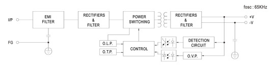
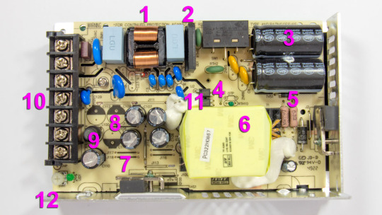
The input voltage is supplied to the input node: RF interference filter (1), a pulse surge limiter (varistor), then the voltage goes to the diode bridge (2) and two input electrolytic capacitors (3). The input voltage selector is also located here. Flyback, built on a MW03A controller (4, installed on the back side of the board) and a power switch (5) on a N-channel MOSFET transistor MMF60R290P. Unfortunately, there is no information about the controller on the Internet. The transistor has a channel resistance of 0.29 ohms at 650 volts and 13 amps. The transformer (6) is entirely covered by the casing, so it is unclear what core material is used. The output rectifier (7) is built using a Schottky diode HBR20150 in a TO-220F package screwed to the side wall and covered with casing. It is basically dual 150V 10A diodes connected in parallel. After the diode there are four output electrolytic capacitors (8) and an additional LC filter. Here (12), there is a small output voltage indicator (green LED) and a regulator (tuning resistor) for adjusting the output voltage. Input and output circuits are connected through a shared screw 7-terminal block (10). 3 terminals for the input line, neutral, and ground wires, and 2 in parallel for common and +24V output.
The main electrolytic capacitors are designed for operating temperatures up to 220°F (105°C), Rubycon. Two optocouplers (11) are installed in the feedback circuit, most likely with phototransistors transmitting control signals from the low-voltage output to the high-voltage input side.
The board has a few cutouts to increase the dielectric strength between the high-voltage and low-voltage sides of the circuit.
The picture shows that the board has three unused spots for storage output capacitors (8), most likely used in the other power supplies of the same series but with different output voltages.
Test conditions
Most tests use metering circuit #1 (see appendices) at 80°F (27°C), 70% relative humidity, and 29.8 inHg pressure.
The measurements were performed without preheating the power supply with a short-term load unless mentioned otherwise.
The following values were used to determine the load level:

Output voltage under a constant load

The high stability of the output voltage should be noted.
Power-on parameters
Powering on at 100% load
The power supply is turned off at least 5 minutes before the test, with a 100% load connected.
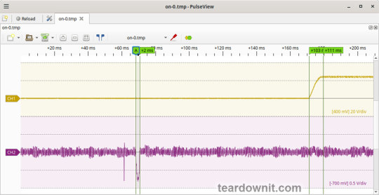
The oscillogram of switching to a 100% load is shown below (channel 1 is the output voltage, and channel 2 is the current consumption from the grid):
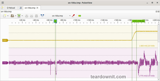
The picture shows three distinguishable phases of the power-on process:
The pulse of the input current charging the input capacitors when connected to the grid has an amplitude of about 7.5 A and a duration of 2 ms.
Waiting for the power supply control circuit to start for about 100 ms.
(Output Voltage Rise Time) Starting the converter, increasing the output voltage, and entering the operating mode) is 8 ms.
(Turn On Delay Time) The entire process of entering the operating mode from the moment of powering on) is 119 ms.
(Output Voltage Overshoot) Output voltage overshoot is absent; the switching process is aperiodic.
Powering on at 0% load
The power supply is turned off at least 5 minutes before the test, with a 100% load connected. Then, the load is disconnected, and the power supply is switched on.
The oscillogram of switching to a 0% load is shown below:
The picture shows three distinguishable phases of the power-on process:
The pulse of the input current charging the input capacitors when connected to the grid has an amplitude of about 7 A and a duration of 2 ms.
Waiting for the power supply control circuit to start for about 103 ms.
(Output Voltage Rise Time) Starting the converter, increasing the output voltage, and entering the operating mode) is 8 ms.
(Turn On Delay Time) The entire process of entering the operating mode from the moment of powering on) is 111 ms.
(Output Voltage Overshoot) Output voltage overshoot is absent; the switching process is aperiodic.
Power-off parameters
The power supply was turned off at 100% load, and the input voltage was nominal at the moment of powering off. The oscillogram of the shutdown process is shown below:

The picture shows two phases of the shutdown process:
(Shut Down Hold Up Time) The supply continues to operate due to the input capacitors holding charge until the voltage across them drops to a certain critical level at which maintaining the output voltage at the nominal level becomes impossible is 31 ms.
(Output Voltage Fall Time) Reduction of the output voltage, stopping voltage conversion, and accelerating the voltage drop is 21 ms.
(Output Voltage Undershoot) Output voltage undershoot is absent, and the shutdown process is aperiodic.
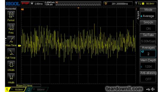
Ripple voltage and current
100% load
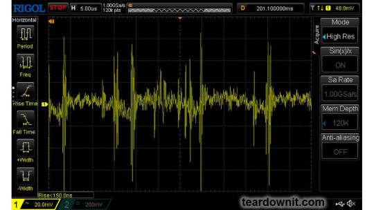
The diagram of the current draw from the grid at 100% load is shown in the oscillogram below. The amplitude of the current is about 7.5 A:
Low-frequency output voltage ripple is under 30 mV (see the oscillogram below):

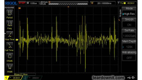
Output voltage ripple at the converter frequency is under 30 mV (see the oscillogram below):

75% load
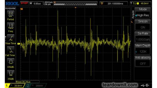
Output voltage ripple at the converter frequency is under 30 mV (see the oscillogram below):
Low-frequency output voltage ripple is under 30 mV (see the oscillogram below):

50% load
Output voltage ripple at the converter frequency stays below 10 mV; see the oscillogram (11):
10% load

0% load
No-load current consumption was measured with a multimeter, which is 60 mA RMS.
(Power Consumption) The first assumption of excessive standby power draw of more than 7 W is wrong since the current in this mode is predominantly reactive. Indeed, the input filter in the circuit contains two capacitors with a capacitance of 0.68 μF each; these low-frequency capacitors are connected in parallel, i.e., an equivalent capacitance of 1.36 μF is connected to the input terminals. A simple calculation shows that the current through these capacitors should be equal to Ic=120×2×pi×60×1.36e-6=61.5 mA. A slight difference from the measured value can be explained by the deviation of the actual parameters from their nominal values and measurement error.
Measuring the exact active power consumption at a 0% load with a basic set of instruments (oscilloscope, multimeter, etc.) is impossible.
Output voltage ripple at the converter frequency is under 20 mV (see the oscillogram below):

The amplitude of low-frequency output voltage ripples is about 25 mV (see the oscillogram below):

Dynamic characteristics
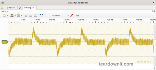
A mode with periodic switching between 50% and 100% load was used to evaluate the dynamic characteristics. The process oscillogram is shown below (17):

It is evident that the supply’s response to loading changes is close to aperiodic, and there is no overshoot, which indicates a good stability margin. The magnitude of the response to load changes is within 200 mV.
Overload protection
The claimed protection type is "hiccup mode, recovers automatically after fault condition is removed". This was confirmed during testing. When a short circuit occurs, the power supply periodically tries to turn back on and, if the overload is still present, turns off again until the next attempt. This operating mode reduces energy losses and heating during overload. Still, it does not allow the parallel connection of multiple power supplies with a common output.
The output current for the overload protection to kick in is 8.5 A.
Input circuit safety assessment
(Input discharge) Safety assessment is based on the discharge time constant of the input circuits when disconnected from the grid; the value is 0.384 s. This means that when operating on a 120 V input voltage, the time required to discharge the input circuits to safe values (<42 V) will be 0.61 s:

Important: The result is valid for this particular power supply unit; it was obtained for testing purposes and should not be taken as a safety guarantee.
Thermal modes
When operating with no load connected, no component overheating had been noticed.
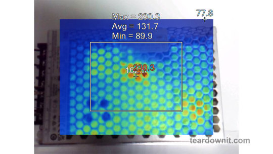
When operating under load, the input diode bridge heats up most noticeably.
With a load of 90% and the top cover closed, the case heats up to approximately 200°F; the hottest spot is located in the area of the diode bridge rectifier.
With a load of 95% and the lid closed, the case temperature reaches 230°F:
The temperature of the bridge rectifier itself is a dangerous 250°F:
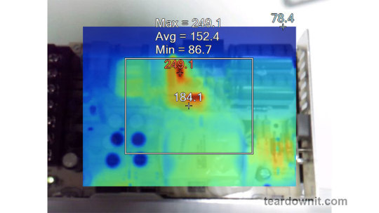
Somewhere around these load values, the power supply goes into a pulse-power-limiting mode and remains in this state either until the load drops or until it cools down. Then this 'heat up', 'limit power', 'cool down', and 'turn back on' cycle repeats.
Other things to consider:
Hot summer weather will decrease the maximum sustainable power output this supply can provide even more.
The tests were conducted with unobstructed air access to the housing for cooling; any changes may increase the heating.
This means that the power supply cannot handle its rated load for a prolonged period with no forced ventilation, and the load should be limited to 5.5 or even 5.0 A.
Conclusions
The reviewed power supply unit has characteristics generally consistent with those declared by the manufacturer, except for the long-term output power, which should be around 120 W.
The build quality is decent; no components clearly unsuitable for the general application, power draw, current, voltage, or temperature were found in the circuit.
The stability of the output voltage should be especially noted.
0 notes