#Raspberry Pi Compute Module 4
Explore tagged Tumblr posts
Visit Tumblr Blog
Explore Tumblr blogs with no restrictions, modern design and the best experience.
Last Seen Tumblr Blogs


Fun Fact
The Tumblr office adopted Tommy, an 11-year-old Pomeranian.
Text
i just think it’s funny that raspberry pi seems to plan their releases around that of apple’s
#stream#both cult followings ….#that im apart of ………#idk i’ve always been an apple fanthem i guess#perhaps it’s also due to me growing up poor & seeing it as a status symbol but by the time the 5s or so was released they had started being#subsidized for the poors following the monopoly breakup w at&t so i had an what was it it was either an 8 or 16gb 4s for 99c in#it was 2014/2015 or so i don’t remember i still have that fucking phone the back cracked bc my sexy fatass geometry teacher fucking stepped#on my binder on accident during a test u know when in school u had to put ur bag or binder at the front of class during tests#but i also got an ipod touch in like 2012 i think loved it it was green my mother got it for my brother & i for christmas#& that’s when i hopped on the Dual Phone Train#never grew out of it#i had an 14 & se 1st gen now i’m triple wielding bc i got robbed so ptsd ive got 12 mini 15 ? 16 ? idk i dont use it it just stays home that#the tx phone bc it doesn’t have a sim card slot as american so it’s esim only therefore literally an ipod#& that’s what i use it as - i also have my us whatsapp on there & i use it to call my banks#but that’s like once a month#so#triple wielding w the se#i hate the new ios like ios 18 it’s gotten too complicated#literally loved apple bc of its simplicity idk as if i didn’t get a pi to get into software & webhosting as was my dream as a child#literally in elementary school i wanted to build my own website so bad i literally went to the library & was reading books on how to build a#server then i asked my parents & they were like ‘wow that’s so cool :) we don’t have any money :) that’s why u were at the library :) & know#so much about libraries :) bc they’re free :) bc ur poor :)’ ALSKALSKALKSLAKSLALSASL#MORE PPL NEED TO USE LIBRARIES#blessed to live like down the street from a library#actually blessed to literally be living in a ‘15 minute city’#also accidentally ordered a compute module 4 so :/#i thought i was ordering the module 5 ALSJALKSLAKSLAKSLAKSLAKSLKSLA#RASPBERRY DROP THE 5S I KNOW U GOT STOCK FUCK U#i’m literally going to make a dual cloud hosting server & also a website host so i can finally provide my family back home w a website for#them to see when i take pics & stuff
1 note
·
View note
Text
A Compact Pi Compute Module Backpack 🍓🥧📸🎒
We used to stock a PiCam Module
that would plug into a Pi CM4 or CM5 - recently we went to restock it, but the vendor hasn't replied to our emails for many months. So, it could be a good time for us to design something that works similarly but with more capabilities. So we tasked Timon
with designing something for us - we just said, "Make the best thing ya can," and he delivered! Check this board out that plugs onto the compute module and provides many great accessories: USB connection for bootloading/USB gadget, USB 3.0 host type A for CM5, micro HDMI, micro SD card for data storage on 'Lite modules, camera connection, and mount, two DSI connectors, fan connect, Stemma QT / Qwiic connection, and RTC battery. There's one shutdown button for CM5 and two GPIO buttons plus one LED. Timon's gonna try to add an EYESPI connector for our next rendering so we can get some I2C/SPI/PWM outputs easily. What do you think? We wanted to keep it compact and not too pricey (aiming for <$30 cost. We'll see if we can get it there) but were able to craft fairly complex projects in a small space.
#raspberrypi#computeModule#electronics#maker#hardware#embedded#engineering#diy#tech#innovation#pcbdesign#usb3#microsd#hdmi#camera#stemmaqt#qwiic#gpio#fan#rtc#devboard#prototyping#opensource#electronicsdesign#robotics#automation#coding#hobbyelectronics#hackerspace#geekstuff
17 notes
·
View notes
Text
clockwork PicoCalc
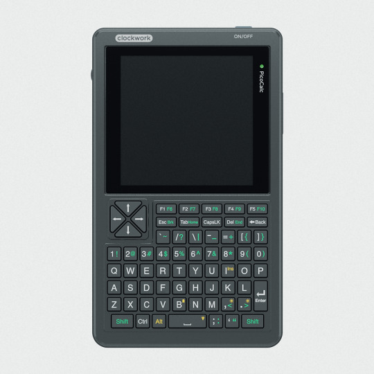


clockwork PicoCalc Back to Basics, rediscover the Golden Age of Computing
Code in BASIC, explore the magic of Lisp, taste the elegance of Unix, play retro games and digital music all in just 260KB memory. Infinite possibilities, inspired by the genius in you!
ClockworkPi v2.0 mainboard
Raspberry Pi Pico 1 H Core module (ARM32-bit Dual-core Cortex M0+, 264KB RAM, 2MB flash)
320x320 4-inch IPS screen (SPI interface)
Ultra-portable QWERTY Backlit keyboard on board (I2C interface)
Dual speaker
ABS plastic shell & 2.5mm Hex key
Tempered glass cover
32GB high-speed SD-card with optimized BASIC firmware
source: clockworkpi.com
7 notes
·
View notes
Text
Hopefully by March, we will be living in London, near to a lovely queer community. But we also find myself during this current social isolation we suffer, exiled from our tools, we miss taking on projects. This needs to change. Unfortunately said tools are currently packed up, awaiting out move.
So, after we have migrated from this dreary town, we will setup our little "lab" again and intend to work on various projects, including:
- A Raspberry Pi Compute Module 4 powered Linux phone with 4G connectivity (initially)
- A Steampunk meets Atompunk desk, based on a nuclear reactor console
- Setting up Home Assistant powered smart tech in the new home, from lights to temperature control, etc
Have any ideas? Let me know! My specialism is Python, though I'm always up for learning something new. Challenges inspire me.
2 notes
·
View notes
Text
Exploring the Possibilities with Raspberry Pi: A Guide to Buying and Utilizing Raspberry Pi 4 and Its Camera Kit
Introduction:
In the world of single-board computers, Raspberry Pi stands out as a powerful and versatile option. The Raspberry Pi Foundation has continuously pushed the boundaries of what can be achieved with these compact devices. In this blog post, we will explore the benefits of Raspberry Pi 4 kit, Raspberry pi buy, and delve into the exciting projects you can undertake using this remarkable technology.
Why Choose Raspberry Pi 4 Camera? Raspberry pi 4 camera is the latest iteration of the Raspberry Pi series, offering improved performance and enhanced features. It comes equipped with a Broadcom BCM2711 quad-core Cortex-A72 processor, clocked at 1.5GHz, which ensures smooth multitasking and faster execution of complex tasks. The availability of up to 8GB of RAM allows for efficient handling of data-intensive applications. With its support for dual-band Wi-Fi and Bluetooth 5.0, Raspberry Pi 4 provides seamless connectivity options for your projects.
Exploring the Camera Capabilities: One of the most exciting features of Raspberry Pi 4 is its compatibility with a dedicated camera module. The Raspberry Pi Camera Module v2 is a high-quality camera that can be easily connected to the board via the camera interface. The camera module offers an 8-megapixel sensor and supports video resolutions up to 1080p, enabling you to capture stunning photos and videos. Its compact size and versatility make it perfect for various applications, including surveillance systems, time-lapse photography, and even computer vision projects.
Where to Buy Raspberry Pi 4 Online: When it comes to purchasing Raspberry Pi 4 and its accessories online, there are several reputable platforms to consider. Some popular options include:
Online Retailers (e.g., Amazon, Robomart, SparkFun) Established Raspberry pi buy online platforms like Amazon, Robomart, and SparkFun also stock Raspberry Pi 4 boards, camera modules, and kits. These retailers often provide customer reviews and ratings, giving you insights into the products before making a purchase.
Specialized Electronics Retailers Various specialized electronics retailers cater specifically to the Raspberry Pi community. These retailers often have a wide range of Raspberry Pi products, including kits that include the camera module.
Exciting Raspberry Pi 4 Projects: Once you have your Raspberry Pi 4 and camera kit, the possibilities for projects are virtually endless. Here are a few ideas to get you started:
Home Surveillance System: Set up a motion-activated camera system to monitor your home remotely and receive alerts on your smartphone.
Wildlife Monitoring: Create a wildlife camera trap that captures photos or videos of animals in their natural habitats.
Time-Lapse Photography: Capture the beauty of nature or the progress of a construction project by creating stunning time-lapse videos.
Facial Recognition: Develop a facial recognition system using the camera module and explore applications in security or access control.
Virtual Assistant: Transform your Raspberry Pi 4 into a voice-controlled assistant by integrating a microphone and speaker.
Conclusion: Raspberry Pi 4, along with its camera module, opens up a world of possibilities for hobbyists, educators, and professionals alike. Whether you're interested in building a smart home system or exploring computer vision applications, Raspberry Pi 4 provides the necessary power and flexibility. With numerous online platforms available to purchase Raspberry Pi 4 and its accessories,
4 notes
·
View notes
Text
Why India’s Drone Industry Needs Periplex: The Hardware Tool Drones Didn’t Know They Needed
As drones fly deeper into critical roles — from agricultural intelligence to autonomous mapping, from disaster response to military ops — the hardware stack that powers them is undergoing a silent revolution.
At the center of that transformation is Periplex — a breakthrough tool from Vicharak’s Vaaman platform that redefines how drone builders can interface with the real world.

What is Periplex?
Periplex is a hardware-generation engine. It converts JSON descriptions like this:{ "uart": [ { "id": 0, "TX": "GPIOT_RXP28", "RX": "GPIOT_RXN28" } ], "i2c": [ { "id": 3, "SCL": "GPIOT_RXP27", "SDA": "GPIOT_RXP24" }, { "id": 4, "SCL": "GPIOL_63", "SDA": "GPIOT_RXN24" } ], "gpio": [], "pwm": [], "ws": [], "spi": [], "onewire": [], "can": [], "i2s": [] }
…into live hardware interfaces, directly embedded into Vaaman’s FPGA fabric. It auto-generates the FPGA logic, maps it to kernel-level drivers, and exposes them to Linux.
Think of it as the “React.js of peripherals” — make a change, and the hardware updates.
Real Drone Applications That Truly Need Periplex
Let’s break this down with actual field-grade drone use cases where traditional microcontrollers choke, and Periplex thrives.
1. Multi-Peripheral High-Speed Data Collection for Precision Agriculture
Scenario: A drone is scanning fields for crop health with:
2 multispectral cameras (I2C/SPI)
GPS + RTK module (2x UART)
Wind sensor (I2C)
Sprayer flow monitor (PWM feedback loop)
ESCs for 8 motors (PWM)
1 CAN-based fertilizer module
The Periplex Edge: Microcontrollers would require multiple chips or muxing tricks, causing delays and bottlenecks. With Periplex:
You just declare all interfaces in a JSON file.
It builds the required logic and exposes /dev/pwm0, /dev/can0, etc.
Zero code, zero hassle, zero hardware redesign.
2. Swarm Communication and Custom Protocol Stacks
Scenario: Swarm drones communicate over:
RF LoRa (custom SPI/UART)
UWB mesh (proprietary protocol)
Redundant backup over CAN
Periplex lets you:
Create hybrid protocol stacks
Embed real-time hardware timers, parity logic, and custom UART framing — none of which are feasible in most MCUs
Replacing Microcontrollers, Not Just Augmenting Them
| Feature | Microcontroller | Periplex on Vaaman | |---------------------------|----------------------------|------------------------------------| | Number of peripherals | Limited (4–6) | Virtually unlimited (30+ possible) | | Reconfiguration time | Flash + reboot | Real-time, dynamic reload | | Timing precision | Software-timer limited | FPGA-grade nanosecond-level timing | | AI compatibility | Not feasible | Integrated (Gati Engine) | | Sensor fusion performance | Bottlenecked | Parallel FPGA pipelines |
Developers Love JSON, Not Register Maps
No more:
Scouring 400-page datasheets
Bitmasking registers for I2C configs
Writing interrupt handlers from scratch
Just declare what you need. Let Periplex do the work. Peripherals become software-defined, but hardware-implemented.
Built in India, for India’s Drone Revolution
Vaaman + Periplex isn’t just about tech. It’s about self-reliance.
India’s defence, agriculture, and logistics sectors need secure, reconfigurable, audit-friendly hardware — not black-box SoCs from questionable supply chains.
Periplex is the hardware engine for Atmanirbhar Bharat in drones.
TL;DR
Periplex lets drones adapt hardware to the mission — instantly.
It replaces tangled microcontroller logic with clean, structured JSON.
It unlocks use cases microcontrollers can’t touch: AI at the edge, dynamic reconfiguration, secure protocol stacks, and more.
And it’s built into Vaaman, India’s first reconfigurable edge computer.
Ready to Get Started?
Explore Vaaman on Crowd Supply Reach out for Periplex SDK access: [email protected]
Raspberry Pi
Drones
Drones Technology
Jetson Orin Nano
Technology
0 notes
Text
Elmalo, let's commit to that direction. We'll start with a robust Sensor Fusion Layer Prototype that forms the nervous system of Iron Spine, enabling tangible, live data connectivity from the field into the AI's processing core. Below is a detailed technical blueprint that outlines the approach, components, and future integrability with your Empathic AI Core.
1. Hardware Selection
Edge Devices:
Primary Platform: NVIDIA Jetson AGX Xavier or Nano for on-site processing. Their GPU acceleration is perfect for real-time preprocessing and running early fusion algorithms.
Supplementary Controllers: Raspberry Pi Compute Modules or Arduino-based microcontrollers to gather data from specific sensors when cost or miniaturization is critical.
Sensor Modalities:
Environmental Sensors: Radiation detectors, pressure sensors, temperature/humidity sensors—critical for extreme environments (space, deep sea, underground).
Motion & Optical Sensors: Insect-inspired motion sensors, high-resolution cameras, and inertial measurement units (IMUs) to capture detailed movement and orientation.
Acoustic & RF Sensors: Microphones, sonar, and RF sensors for detecting vibrational, audio, or electromagnetic signals.
2. Software Stack and Data Flow Pipeline
Data Ingestion:
Frameworks: Utilize Apache Kafka or Apache NiFi to build a robust, scalable data pipeline that can handle streaming sensor data in real time.
Protocol: MQTT or LoRaWAN can serve as the communication backbone in environments where connectivity is intermittent or bandwidth-constrained.
Data Preprocessing & Filtering:
Edge Analytics: Develop tailored algorithms that run on your edge devices—leveraging NVIDIA’s TensorRT for accelerated inference—to filter raw inputs and perform preliminary sensor fusion.
Fusion Algorithms: Employ Kalman or Particle Filters to synthesize multiple sensor streams into actionable readings.
Data Abstraction Layer:
API Endpoints: Create modular interfaces that transform fused sensor data into abstracted, standardized feeds for higher-level consumption by the AI core later.
Middleware: Consider microservices that handle data routing, error correction, and redundancy mechanisms to ensure data integrity under harsh conditions.
3. Infrastructure Deployment Map
4. Future Hooks for Empathic AI Core Integration
API-Driven Design: The sensor fusion module will produce standardized, real-time data feeds. These endpoints will act as the bridge to plug in your Empathic AI Core whenever you’re ready to evolve the “soul” of Iron Spine.
Modular Data Abstraction: Build abstraction layers that allow easy mapping of raw sensor data into higher-level representations—ideal for feeding into predictive, decision-making models later.
Feedback Mechanisms: Implement logging and event-based triggers from the sensor fusion system to continuously improve both hardware and AI components based on real-world performance and environmental nuance.
5. Roadmap and Next Steps
Design & Prototype:
Define the hardware specifications for edge devices and sensor modules.
Develop a small-scale sensor hub integrating a few key sensor types (e.g., motion + environmental).
Data Pipeline Setup:
Set up your data ingestion framework (e.g., Apache Kafka cluster).
Prototype and evaluate basic preprocessing and fusion algorithms on your chosen edge device.
Field Testing:
Deploy the prototype in a controlled environment similar to your target extremes (e.g., a pressure chamber, simulated low-gravity environment).
Refine data accuracy and real-time performance based on initial feedback.
Integration Preparation:
Build standardized API interfaces for future connection with the Empathic AI Core.
Document system architecture to ensure a smooth handoff between the hardware-first and AI-core teams.
Elmalo, this blueprint establishes a tangible, modular system that grounds Iron Spine in reality. It not only demonstrates your vision but also builds the foundational “nervous system” that your emergent, empathic AI will later use to perceive and interact with its environment.
Does this detailed roadmap align with your vision? Would you like to dive further into any individual section—perhaps starting with hardware specifications, software configuration, or the integration strategy for the future AI core?
0 notes
Text
Raspberry Pi slices Compute Module 4 prices
http://securitytc.com/TKWTNq
0 notes
Text
Chatgpt computer communication design
Designing a computer circuit where two computers communicate with each other and "teach themselves" using an Arduino board involves a combination of hardware setup and software programming. Here’s a general guide to get you started:
1. Basic Concept
Two Computers (PCs or Microcontrollers): These are the two devices that will communicate and learn from each other. Each will run a program for self-learning.
Arduino Board: The Arduino will facilitate the communication between the two computers and control the process. It could also be part of the system performing calculations or simulations.
Communication Protocol: The two computers will need to communicate with each other. For simplicity, we can use serial communication (UART) or I2C with the Arduino acting as the intermediary.
2. Hardware Components
Arduino Board (e.g., Arduino Uno, Nano, or Mega)
Two Computers (PCs or other microcontrollers, like Raspberry Pi or other Arduino boards)
Communication Module: If you are using something like a Raspberry Pi or another microcontroller, you might need USB-to-Serial adapters or Bluetooth/Wi-Fi modules (e.g., ESP8266/ESP32, HC-05).
Power Supply: Proper power sources for the Arduino and computers.
Cables: USB, serial cables, or jumper wires for communication.
3. Circuit Design
Here is a high-level overview of the connections between the Arduino and the two computers.
Arduino and PC1 (Computer 1):
Connect the Arduino to PC1 via USB or UART communication pins (TX/RX pins if using serial).
Arduino and PC2 (Computer 2):
If you are using a second microcontroller (like another Arduino or a Raspberry Pi), connect them to the Arduino board using a communication protocol (e.g., I2C or UART).
The two computers could either communicate directly over a network (like Ethernet or Wi-Fi) or through serial communication.
For this example, let’s assume you are using UART for communication between the Arduino and both computers. You can use the TX/RX pins on the Arduino and connect them to the USB-to-Serial adapters connected to each computer.
4. Software Design
The software should allow the computers to "teach themselves," which likely means implementing some form of machine learning or pattern recognition. For simplicity, let’s outline how you could set up communication, with the learning part handled on the computers.
Arduino Code: The Arduino will act as the middleman for the communication. It will receive data from one computer, send it to the other, and also handle basic processing or simulation. It can be programmed to send responses or instructions back to the computers.
// Simple Arduino code for UART communication void setup() { Serial.begin(9600); // Start the serial communication at 9600 baud } void loop() { if (Serial.available()) { char incomingByte = Serial.read(); // Read incoming byte Serial.print("Received: "); Serial.println(incomingByte); // Send back the received byte } }
Computer 1 and Computer 2 Code: Each computer should run a program that will send data to the Arduino and receive responses. This could be a simple Python script or C++ program for serial communication.
Example Python Script: Here’s a basic Python script that can run on each computer. This script will send data to the Arduino and read the response back.import serial import time # Open serial port (make sure to change COM port for your system) ser = serial.Serial('COM3', 9600) # Change COM port as needed time.sleep(2) # Wait for the serial connection to initialize # Send data to Arduino ser.write(b'Hello Arduino!\n') # Read response while True: if ser.in_waiting > 0: response = ser.readline().decode('utf-8').strip() print(f"Arduino says: {response}") break ser.close()
This Python script could run on Computer 1, while a similar script runs on Computer 2. Both will send messages to the Arduino and receive feedback.
5. Self-Learning Simulation
To simulate the "self-teaching" aspect, each computer can use machine learning algorithms. You could start with something simple like linear regression or a decision tree. The computers could send random data points to each other and exchange feedback on whether the predictions made by each other are correct.
Computer 1 could generate a random dataset and send it to Computer 2.
Computer 2 processes the data, makes predictions, and sends the feedback back.
Computer 1 uses this feedback to adjust its learning algorithm (e.g., adjust weights in a simple linear regression model).
Example of a Simple Learning Process: Each computer could adjust its internal model based on the received feedback, similar to how a neural network or other machine learning models learn. The Arduino could be involved in simple processing tasks or sending acknowledgment signals when certain thresholds are reached (e.g., "success" or "failure").
6. Scaling Up
If you want to scale up the project to involve more complex learning or higher levels of interaction, you could use a more advanced platform such as a Raspberry Pi or ESP32/ESP8266 for networking and faster processing, where each computer uses a machine learning library (like TensorFlow Lite or scikit-learn).
7. Final Setup
Computer 1 and Computer 2 run machine learning algorithms that adjust based on feedback.
Arduino manages data flow between the computers and possibly performs basic learning tasks like adjusting variables or sending commands.
The entire system simulates a network where two computers are learning from each other.
This is a high-level overview, and there are many ways to implement it depending on the complexity of the communication and learning algorithm you want to achieve. Would you like to dive deeper into any specific area or need more detailed code for the project?
Creating two PCs from scratch using Arduino boards is an interesting challenge, but it's important to note that a full-fledged personal computer involves much more complexity than an Arduino is capable of. However, you can certainly simulate basic "PC-like" behavior using Arduino boards, where each "PC" would be a microcontroller (Arduino) with some level of functionality, communication, and processing.
High-Level Concept
Each Arduino board would act as a basic computing unit (like a simplified "PC"), running simple programs, processing input, and communicating with each other. While these "PCs" won't have the advanced features of a real computer (like an OS, GUI, or complex processing power), they can serve as learning devices or communication nodes in a network.
To make two PCs communicate with each other using an Arduino board, the Arduino acts as an intermediary. The Arduino will handle the communication between the two PCs, either via a serial connection (UART), I2C, or wireless communication (e.g., Bluetooth/Wi-Fi). Below is a guide on how to set up such a system:
1. Hardware Setup
Here, I'll describe a setup where two PCs communicate via an Arduino board using serial communication (UART). The Arduino will act as a mediator, forwarding messages between the two computers.
Components Needed:
Arduino board (e.g., Arduino Uno, Nano, Mega)
2 PCs (PC1 and PC2)
USB-to-Serial adapters (if using UART)
Jumper wires (if using direct communication between Arduino and PC)
Connections:
PC1 <-> Arduino: The first PC will communicate with the Arduino using its USB port (acting as a serial port).
PC2 <-> Arduino: The second PC will communicate via another USB-to-Serial adapter or possibly the second USB port of the Arduino (if the Arduino model supports multiple serial connections, e.g., Mega).
In simpler terms:
Arduino will be connected via USB to PC1.
PC2 will be connected to Arduino's serial pins (TX/RX) or using a USB-to-Serial adapter.
2. Arduino Code
The Arduino will need to read from one serial port (PC1) and forward the data to another serial port (PC2) and vice versa. The following is a simple Arduino sketch for this task.// Arduino code for mediating between two PCs void setup() { // Start serial communication with both computers Serial.begin(9600); // For communication with PC1 Serial1.begin(9600); // For communication with PC2 (if using Arduino Mega or another board with multiple serial ports) } void loop() { // Check if data is available from PC1 (connected to Serial) if (Serial.available() > 0) { char dataFromPC1 = Serial.read(); // Read data from PC1 Serial1.write(dataFromPC1); // Send data to PC2 (connected to Serial1) } // Check if data is available from PC2 (connected to Serial1) if (Serial1.available() > 0) { char dataFromPC2 = Serial1.read(); // Read data from PC2 Serial.write(dataFromPC2); // Send data to PC1 (connected to Serial) } }
Explanation of the Code:
Serial.begin(9600): Initializes communication with PC1.
Serial1.begin(9600): Initializes communication with PC2. (Note: Only available on boards with multiple UARTs like Arduino Mega, if using an Arduino Uno, you’ll need a USB-to-Serial adapter for PC2).
Serial.read(): Reads data from one serial port.
Serial.write(): Sends data to the other serial port.
3. Software on the PCs
On each of the two PCs, you will run a program that communicates with the Arduino via a serial connection. You can use Python to interface with the Arduino. Here’s a simple Python example that reads data from the Arduino and sends data back.
Python Code for PC1:
import serial import time # Connect to Arduino via serial port (Adjust the port name as needed) ser = serial.Serial('COM3', 9600) # Replace 'COM3' with your Arduino's port time.sleep(2) # Wait for the serial connection to establish # Send data to Arduino (which will forward to PC2) ser.write(b'Hello from PC1!\n') # Read data from Arduino (which is coming from PC2) while True: if ser.in_waiting > 0: response = ser.readline().decode('utf-8').strip() print(f"Received from PC2: {response}") break ser.close()
Python Code for PC2:
import serial import time # Connect to Arduino via serial port (Adjust the port name as needed) ser = serial.Serial('COM4', 9600) # Replace 'COM4' with your Arduino's port time.sleep(2) # Wait for the serial connection to establish # Read data from Arduino (which is coming from PC1) while True: if ser.in_waiting > 0: message = ser.readline().decode('utf-8').strip() print(f"Received from PC1: {message}") # Send data back to Arduino (which will forward to PC1) ser.write(b'Hello from PC2!\n') break ser.close()
4. Explanation of the PC Software:
Python serial library: Used to open a serial connection to the Arduino.
ser.write(): Sends data from PC1 or PC2 to the Arduino.
ser.readline(): Reads incoming data from the Arduino, which is forwarded from the other PC.
Time Delays: time.sleep(2) ensures that the serial connection is established before communication begins.
5. Communication Flow
PC1 sends a message (e.g., "Hello from PC1") to the Arduino.
The Arduino forwards the message to PC2.
PC2 receives the message, processes it, and sends a response back to the Arduino (e.g., "Hello from PC2").
The Arduino forwards the message back to PC1.
6. Adjusting for More Complex Setups
If you are using an Arduino Uno (which has only one serial port), you’ll need an additional USB-to-Serial adapter to handle communication with both PCs. Alternatively, you can use an Arduino Mega, which has multiple serial ports (like Serial, Serial1, Serial2, etc.).
For the Arduino Mega, you can use Serial for PC1 and Serial1 for PC2, as shown in the code above.
For PC2, you might need a USB-to-Serial adapter if you're not using an Arduino Mega.
7. Next Steps
To make the setup more advanced, you can:
Add error handling and retry mechanisms for more robust communication.
Implement data processing algorithms to simulate machine learning (e.g., a simple model for each PC that "learns" from the data it receives).
Use wireless communication like Bluetooth or Wi-Fi if you don't want to rely on USB connections.
Would you like to explore how to expand this further or add more complexity to the system? Let me know!
Here’s how you might approach creating two Arduino-based "PCs" from scratch:
1. Basic Requirements and Constraints
You’re working with Arduino boards, which are microcontrollers with limited processing power, memory, and storage compared to a real PC. The Arduino can run basic programs, perform calculations, and communicate with other devices, but it cannot run complex software like a PC.
To simulate PCs, you'll need:
Arduino microcontroller boards (e.g., Arduino Uno, Nano, Mega, etc.)
Inputs/outputs (e.g., buttons, LEDs, displays)
Communication method between the two Arduinos (e.g., UART serial, I2C, or even wireless)
Storage (limited, but can use EEPROM or SD card modules)
Basic display (e.g., an LCD or LED screen for output)
2. Building the Two "PCs" with Arduino
Each Arduino board will act as one "PC." Here’s how you can conceptualize the setup:
Arduino 1 (PC1): Will handle user input and perform computations.
Arduino 2 (PC2): Will also handle user input and perform computations. It will communicate with PC1 to share or exchange data.
The communication between the two PCs can be done using serial communication (UART) or I2C.
3. Basic Hardware Setup for Each PC
Each "PC" could have:
Buttons or switches to simulate input (e.g., user input or commands).
LCD or 7-segment display for output (or use an LED to indicate activity).
Communication interface to talk to the other PC (e.g., UART or I2C).
SD card or EEPROM to simulate storage.
Components Needed:
2 Arduino boards (e.g., Arduino Uno or Nano)
1 LCD display (16x2 or 20x4 for basic text output)
2 push buttons (to simulate input)
2 LEDs (to indicate some activity or status)
2 USB-to-Serial adapters (if using UART communication between PCs)
1 I2C or UART communication method
1 SD card module (optional for storage simulation)
4. Software Design for the "PCs"
Each Arduino PC will need a program to read inputs, perform some basic computation, and send/receive data to/from the other PC. Here’s a simple breakdown of the software for each Arduino:
Arduino PC1 (PC1 Sketch)
This sketch allows PC1 to process input (button presses), perform simple calculations, and send/receive data from PC2.#include <Wire.h> // For I2C communication (if using I2C) #include <LiquidCrystal_I2C.h> // For LCD display // Initialize the LCD (change pin numbers according to your setup) LiquidCrystal_I2C lcd(0x27, 16, 2); // Input and output pins int buttonPin = 7; // Pin for button input int ledPin = 13; // Pin for LED output void setup() { // Start communication Wire.begin(); // Start I2C communication if using I2C lcd.begin(16, 2); pinMode(buttonPin, INPUT); pinMode(ledPin, OUTPUT); lcd.print("PC1: Ready"); delay(2000); // Wait for 2 seconds } void loop() { int buttonState = digitalRead(buttonPin); // Read button state if (buttonState == HIGH) { // If button is pressed digitalWrite(ledPin, HIGH); // Turn on LED lcd.clear(); lcd.print("Button Pressed"); // Send data to PC2 (via I2C or serial) Wire.beginTransmission(8); // 8 is the I2C address of PC2 Wire.write("PC1: Button Pressed"); Wire.endTransmission(); } else { digitalWrite(ledPin, LOW); // Turn off LED } delay(100); // Small delay to avoid bouncing }
Arduino PC2 (PC2 Sketch)
This sketch for PC2 will receive data from PC1 and display it on the LCD, simulating output.#include <Wire.h> // For I2C communication (if using I2C) #include <LiquidCrystal_I2C.h> // For LCD display LiquidCrystal_I2C lcd(0x27, 16, 2); // LCD setup void setup() { Wire.begin(8); // Set PC2's I2C address to 8 Wire.onReceive(receiveEvent); // Define the event handler for receiving data lcd.begin(16, 2); // Start the LCD display lcd.print("PC2: Ready"); } void loop() { // Main loop does nothing, waiting for incoming data } void receiveEvent(int bytes) { String message = ""; // Initialize an empty string for the message while (Wire.available()) { message += (char)Wire.read(); // Read each byte and convert to character } // Display the received message on LCD lcd.clear(); lcd.print("PC2: "); lcd.print(message); // Print received message on LCD }
5. How They Communicate:
I2C Communication: In this setup, PC1 sends a message to PC2 using I2C. This allows you to connect the two Arduinos with just two wires (SDA, SCL) and share data.
Serial Communication (UART): Alternatively, if you're using UART (Serial) communication, PC1 sends data to PC2 via the Arduino’s TX/RX pins and vice versa.
6. Adding Storage (Optional)
To simulate storage, you can attach an SD card module to the Arduino. The Arduino can read/write simple text files or store computational results on the SD card.
Example of using an SD card module on PC1:#include <SPI.h> #include <SD.h> File myFile; void setup() { Serial.begin(9600); if (!SD.begin(4)) { Serial.println("SD card initialization failed!"); return; } myFile = SD.open("log.txt", FILE_WRITE); if (myFile) { myFile.println("PC1: Data Log"); myFile.close(); } else { Serial.println("Error opening log.txt"); } } void loop() { // Example of logging data continuously myFile = SD.open("log.txt", FILE_WRITE); if (myFile) { myFile.println("New Data Recorded"); myFile.close(); } delay(1000); // Wait for 1 second }
7. Expanding the "PCs"
You can add more features to each Arduino "PC," such as:
User input: Keyboard or mouse emulation.
Network Communication: Use Wi-Fi or Ethernet modules (like ESP8266 or Ethernet shield) to allow the two PCs to communicate over a network.
Processing: Implement simple algorithms or calculations on each Arduino to make them more like basic computers.
8. Limitations
Remember that an Arduino board is not a real PC, and it has significant limitations:
Limited processing power and memory.
No operating system or advanced software.
Minimal input/output capabilities.
But it is still a great way to learn about the basics of computer-like behavior, communication, and microcontroller programming.
Conclusion
While building a full-fledged PC using Arduino isn’t feasible, you can create two basic "PC-like" systems by using Arduino boards to simulate basic functionality such as processing, input/output, communication, and storage. This setup is a great way to learn about how computers work at a fundamental level, as well as how data is shared and processed between multiple devices.
Would you like to explore any specific part of the project further or need help with something else?
0 notes
Text
What Are the Essential Tools and Equipment for a STEM Lab in Rajasthan?

Introduction: Building a Future-Ready STEM Lab in Rajasthan
With Rajasthan embracing technology-driven education, setting up a STEM lab in Rajasthan has become essential for schools. A well-equipped STEM lab in Rajasthan provides hands-on learning experiences that prepare students for careers in engineering, robotics, AI, and more. But what tools and equipment are needed to build a high-quality STEM lab in Rajasthan?
Here’s a complete guide to the essential tools and equipment for a cutting-edge STEM lab in Rajasthan.
1. Robotics Kits & Coding Tools for a STEM Lab in Rajasthan
Robotics and coding are integral parts of STEM education. Schools need:
Arduino & Raspberry Pi Kits – For learning programming, electronics, and automation
LEGO Mindstorms & VEX Robotics Kits – To build and program robots
Scratch & Python Coding Platforms – For beginner-friendly coding exercises
Drones & AI Modules – To introduce students to artificial intelligence and automation
These tools help students develop logical thinking and computational skills, making them ready for future careers in technology. A STEM lab in Rajasthan equipped with robotics fosters innovation and creativity.
2. 3D Printers & Prototyping Equipment for a STEM Lab in Rajasthan
Innovation thrives when students can create prototypes of their ideas. A STEM lab in Rajasthan should include:
3D Printers (like Creality or Ultimaker) – For designing and printing functional models
Laser Cutters & CNC Machines – To teach students about precision manufacturing
3D Modeling Software (Tinkercad, Fusion 360) – To design real-world engineering projects
By incorporating prototyping tools, students in STEM labs in Rajasthan gain exposure to product development, engineering, and entrepreneurship.
3. Science & Electronics Experiment Kits in a STEM Lab in Rajasthan
Hands-on experiments make learning science interactive and engaging. Schools should equip their STEM lab in Rajasthan with:
Physics Kits (Newton’s Laws, Optics, and Electromagnetism Experiments)
Chemistry Kits (Safe Lab Chemicals, Beakers, and Reaction Experiments)
Biology Kits (Microscopes, DNA Extraction, and Ecosystem Models)
Circuit Boards & Soldering Kits – To learn about electrical engineering and IoT
With these kits, students in STEM labs in Rajasthan can explore scientific concepts practically, strengthening their understanding and problem-solving skills.
4. AI & Machine Learning Tools for a STEM Lab in Rajasthan
With the rise of AI and data science, it’s crucial to introduce students to basic AI concepts. Essential tools for a STEM lab in Rajasthan include:
AI Development Boards (Jetson Nano, Google Coral) – For experimenting with AI projects
Machine Learning Platforms (Google Colab, TensorFlow, Teachable Machine) – For building AI models
Speech & Image Recognition Kits – To introduce students to computer vision and natural language processing
AI tools allow students in STEM labs in Rajasthan to work on cutting-edge projects, boosting their career opportunities in AI and automation.
5. IoT & Smart Technology Kits for a STEM Lab in Rajasthan
IoT is transforming industries, and students must learn how smart devices work. Schools should include in their STEM lab in Rajasthan:
IoT Development Kits (ESP8266, NodeMCU, Arduino IoT Cloud)
Sensors (Temperature, Motion, Humidity, RFID) – To build smart home and automation projects
Wireless Modules (Bluetooth, Wi-Fi, LoRaWAN) – To introduce connected device technology
With IoT tools, students in STEM labs in Rajasthan can develop real-world smart solutions, preparing them for the future of technology.
6. Renewable Energy & Environmental Science Kits in a STEM Lab in Rajasthan
Sustainability is a key focus in Rajasthan, and students should learn about renewable energy sources. A STEM lab in Rajasthan should include:
Solar Panel Kits – To teach about solar energy and power generation
Wind Turbine Models – For understanding wind energy
Water Purification & Conservation Experiments – To promote sustainability projects
These tools help students in STEM labs in Rajasthan develop eco-friendly solutions for environmental challenges.
7. Virtual & Augmented Reality (VR/AR) Systems in a STEM Lab in Rajasthan
Immersive learning through VR and AR makes STEM education more engaging. Schools should invest in:
VR Headsets (Oculus Quest, HTC Vive) – To explore virtual science labs and simulations
AR Learning Apps (Google Expeditions, Merge Cube) – For interactive learning experiences
3D Anatomy & Space Exploration Software – To make subjects like biology and astronomy exciting
By integrating VR and AR, students in STEM labs in Rajasthan experience interactive, hands-on education, improving conceptual understanding.
Start Building a STEM Lab in Rajasthan Today!
Setting up a STEM lab in Rajasthan is an investment in the future. With the right tools, students can:
Develop critical problem-solving skills
Engage in hands-on, innovative learning
Prepare for future careers in science and technology
Want to equip your school with a high-tech STEM lab in Rajasthan? Contact us today to explore funding options and expert guidance!
0 notes
Text
Einstieg ins Chia-Mining: Testbericht zum Bitcoin Merch Chia Miner 9TB Kit

Kryptowährungen werden immer vielseitiger, und der Einstieg ins Mining wird dank neuer Lösungen einfacher. Mit dem "Bitcoin Merch Chia Miner 9TB Kit" gibt es eine einfache Möglichkeit, in das Chia-Mining einzusteigen. In diesem Beitrag stelle ich das System vor, erkläre, was die Währung Chia (XCH) ausmacht, und wie sie sich vom bekannten Bitcoin unterscheidet. https://youtu.be/YBOQzr8eOzM Hinweis: Ich habe dieses Kit von BitcoinMerch.com kostenfrei erhalten, um es zu testen und darüber zu berichten. Die hier geäußerten Meinungen basieren auf meinen eigenen Erfahrungen.
Was ist Chia (XCH) und wie unterscheidet es sich von Bitcoin?
Chia ist eine Kryptowährung, die auf einen umweltfreundlicheren Ansatz setzt. Statt auf energieintensives Mining wie bei Bitcoin (Proof-of-Work) siehe Bitaxe Gamma, basiert Chia auf dem sogenannten Proof-of-Space-and-Time-Verfahren. Dabei wird Speicherplatz anstelle von Rechenleistung genutzt. Das macht Chia deutlich stromsparender und nachhaltiger. Gleichzeitig bleibt die Sicherheit des Netzwerks gewährleistet.
Das Chia Miner 9TB Kit im Überblick
Das "Bitcoin Merch Chia Miner 9TB Kit" richtet sich sowohl an Anfänger als auch an erfahrene Miner. Es enthält folgende Komponenten: - Hauptmodul (Evergreen Hub): Die zentrale Einheit für den Betrieb des Systems. - Erweiterungspaket: Ermöglicht eine einfache Erweiterung des Systems bei steigenden Anforderungen. - Netzteil (10A) mit Verteiler: Sorgt für eine stabile Stromversorgung. - Netzwerkkabel: Ermöglicht eine schnelle Verbindung zum Internet. - USB-Kabel: Verbindet die einzelnen Komponenten miteinander. - 90 Tage Garantie: Schutz bei technischen Problemen.

XCH Chia Miner von Bitcoin Merch

RJ45 Netzwerkkabel

10A Stromadapter

Stromkabel für US Markt

Stromverteilerkabel für mehrere Chia Miner Geräte

USB3 Datenkabel Ein Blick auf die verbauten Komponenten Nach genauerer Prüfung der Hardware fielen einige interessante Details auf: - Raspberry Pi 4 mit 32GB SD-Karte: Dieser Mini-Computer ist das Herzstück des Systems. Er ist leistungsfähig genug, um das Chia-Mining zu steuern. - 10 TB Festplatte mit Lüfter: Der Speicherplatz ist entscheidend für das Chia-Mining. Hier wird auf eine klassische Festplatte gesetzt, die zwar preiswerter als eine SSD ist, jedoch langsamer arbeitet. - Einfache RGB-LED: Dieses Modul stammt aus der Mikrocontroller-Programmierung und dient zur Visualisierung des aktuellen Status des Systems. So kann man den Status schnell erkennen, ohne sich am Frontend anzumelden. Insgesamt setzt das Kit auf günstige, aber bewährte Hardware. Dies macht den Einstieg ins Chia-Mining erschwinglich, auch wenn keine High-End-Komponenten verwendet werden.

Chia Miner mit Raspberry Pi + RGB LED + Spannungskonverter

Spannungskonverter von 12V auf 5V

40 mm Lüfter zum kühlen des Raspberry Pi im Chia Miner von Bitcoin Merch


Raspberry Pi 4B mit passiven Kühlkörper

günstiges RGB LED Modul Interessanterweise handelt es sich bei der HDD um eine No-Name-Version ohne ersichtliche Markenbezeichnung. Eine Google-Suche nach weiteren Informationen zur genauen Modellbezeichnung oder technischen Details ergab keine Ergebnisse. Daher lässt sich die Qualität und Langlebigkeit der Festplatte nur schwer einschätzen.

10 TB HDD aus dem Chia Miner von Bitcoin Merch

40 mm Lüfter zum kühlen der HDD

Stromversorgungsmodul für die HDD
Herausforderungen bei der Einrichtung
Für die Einrichtung des Kits wird eine spezielle App benötigt, die jedoch nicht mehr im offiziellen Google Play Store verfügbar ist. Stattdessen muss man eine nicht zertifizierte APK-Datei herunterladen und installieren. Dies birgt ein potenzielles Sicherheitsrisiko, da der Entwickler der App nicht bekannt ist. Um meine privaten Daten zu schützen, habe ich testweise ein altes Handy verwendet. Dazu habe ich ein neues Google-Konto erstellt, das kostenfrei ist, und die App darauf installiert. Dieser Ansatz bietet eine gewisse Sicherheit, ist jedoch keine Lösung für jeden Nutzer. Dennoch ist dies ein praktikabler Weg, um das Kit risikofrei einzurichten.
Besondere Merkmale des Kits
Das Kit bietet einige interessante Vorteile: - Einfache Einrichtung: Auch Einsteiger können das System schnell in Betrieb nehmen. - Erweiterbarkeit: Das System kann bei Bedarf problemlos erweitert werden. - Bonus-NFT: Mit dem Kauf des Kits erhält man ein exklusives digitales Sammlerstück.
Mein Fazit zum Bitcoin Merch Chia Miner
Das "Bitcoin Merch Chia Miner 9TB Kit" ist ideal für alle, die ohne großen Aufwand in das Chia-Mining einsteigen möchten. Die verwendeten Komponenten sind solide und funktional, auch wenn sie eher einfach gehalten sind. Besonders für Einsteiger ist dieses Kit eine gute Wahl, da es alles bietet, was für den Start notwendig ist. Im nächsten Beitrag werde ich zeigen, wie die Einrichtung funktioniert und wie sich das System im Alltag bewährt. Read the full article
0 notes
Text
DIY Smart Lock with Facial Recognition
Introduction
Welcome to our DIY project guide on building a Smart Lock with Facial Recognition! In this age of technological advancements, ensuring the security of our homes is more important than ever. This innovative project combines IoT and computer vision to create a smart lock that grants access based on facial recognition, providing enhanced security for your home. Let’s dive into how to build this project step by step!

Why Build a Smart Lock?
Traditional locks can be cumbersome and easily compromised. A smart lock with facial recognition offers a high level of security by allowing only authorized users to enter. Plus, with remote access capabilities, you can monitor and control your door lock from anywhere, giving you peace of mind.
Benefits of a Smart Lock:
Enhanced Security: Only authorized faces can unlock the door.
Convenience: No need for physical keys or codes.
Remote Monitoring: Control access from your smartphone.
Real-Time Notifications: Get alerts when someone tries to access your door.
Key Components and Technologies
To build your smart lock, you will need the following components:
Raspberry Pi: The brain of your smart lock. A Raspberry Pi 3 or 4 is ideal.
Camera Module: For capturing facial images.
Servo Motor or Solenoid: To act as the locking mechanism.
OpenCV: A powerful computer vision library for facial recognition.
Cloudtopiaa Cloud Services: For remote access, data storage, and notifications.
Breadboard and Jumper Wires: For easy connections.
Additional Tools:
Power supply for the Raspberry Pi
A small project enclosure to house the components
Optional: a push button for manual locking/unlocking
Step-by-Step Guide
Step 1: Set Up Your Raspberry Pi
Install the Operating System: Download and install Raspberry Pi OS on your Raspberry Pi. You can use the Raspberry Pi Imager for an easy setup.
Connect the Camera Module: Attach the camera module to the Raspberry Pi. Ensure it’s enabled by running the following command in the terminal:
sudo raspi-config
2. Navigate to Interfacing Options and enable the camera.
Step 2: Install Required Libraries
Open the terminal on your Raspberry Pi and install the necessary librariessudo apt-get update sudo apt-get install python3-opencv
Step 3: Program Facial Recognition
Create a Python script to implement facial recognition using OpenCV. Here’s a basic example to get you started:import cv2
# Load the Haar Cascade for face detection face_cascade = cv2.CascadeClassifier(cv2.data.haarcascades + 'haarcascade_frontalface_default.xml')
# Initialize the camera camera = cv2.VideoCapture(0)
while True: # Capture frame-by-frame ret, frame = camera.read() gray = cv2.cvtColor(frame, cv2.COLOR_BGR2GRAY)
# Detect faces faces = face_cascade.detectMultiScale(gray, scaleFactor=1.1, minNeighbors=5) # Draw rectangles around detected faces for (x, y, w, h) in faces: cv2.rectangle(frame, (x, y), (x + w, y + h), (255, 0, 0), 2)
# Display the resulting frame cv2.imshow('Face Detection', frame)
if cv2.waitKey(1) & 0xFF == ord('q'): break
# Release the camera and close windows camera.release() cv2.destroyAllWindows()
Step 4: Control the Locking Mechanism
Integrate a servo motor or solenoid to act as your locking mechanism. Connect it to a GPIO pin on the Raspberry Pi and update your script to unlock the door when a recognized face is detected.import RPi.GPIO as GPIO
# Set up GPIO for servo motor LOCK_PIN = 17 # Choose an available GPIO pin GPIO.setmode(GPIO.BCM) GPIO.setup(LOCK_PIN, GPIO.OUT)
def unlock_door(): GPIO.output(LOCK_PIN, GPIO.HIGH) # Unlock time.sleep(5) # Keep unlocked for 5 seconds GPIO.output(LOCK_PIN, GPIO.LOW) # Lock again
Step 5: Implement Facial Recognition Logic
You’ll need to create a mechanism to recognize faces. Start by capturing and storing images of authorized users. Modify your script to compare live images with stored images.
Step 6: Cloud Integration with Cloudtopiaa
To enable remote access and notifications for your smart lock, we’ll set up Cloudtopiaa. Follow these steps:
Sign Up for Cloudtopiaa: Create an account on Cloudtopiaa and log in.
Create a New Project: In the Cloudtopiaa dashboard, create a new project for your smart lock application.
Set Up Database: Create a database to store authorized user data (e.g., facial images or user IDs) and logs of access attempts.
Develop API Endpoints:
Create an endpoint to send facial recognition data to the cloud for analysis.
Set up another endpoint to receive access notifications and alerts.
Implement HTTP Requests: In your Python script, use the requests library to communicate with Cloudtopiaa. Here’s an example of how to send data:
import requests
def send_to_cloud(face_data): url = "https://api.cloudtopiaa.com/your-endpoint" # Replace with your actual endpoint response = requests.post(url, json=face_data) return response.status_code
5. Remote Access Setup: Use Cloudtopiaa’s features to allow remote monitoring and control of your smart lock. You can implement webhooks or notifications to alert you whenever someone attempts to unlock the door.
Step 7: Final Assembly
Assemble all components in a project enclosure.
Mount the camera at eye level on your door.
Ensure the servo motor or solenoid is securely attached to the locking mechanism.
Conclusion-
Congratulations! You have successfully built a DIY Smart Lock with Facial Recognition. This project not only enhances your home security but also demonstrates your skills in computer vision, IoT security, and hardware-software integration.
Additional Resources
OpenCV Documentation
Raspberry Pi Documentation
Cloudtopiaa Documentation — For more details on using their cloud services.
#tech4bizsolutins #DIYSmartLock #FacialRecognition #HomeSecurity #SmartHome #TechDIY #InnovativeSecurity #FacialRecognitionLock #HomeAutomation #SmartTech #SecureHome #cloudtopiaa
0 notes
Text
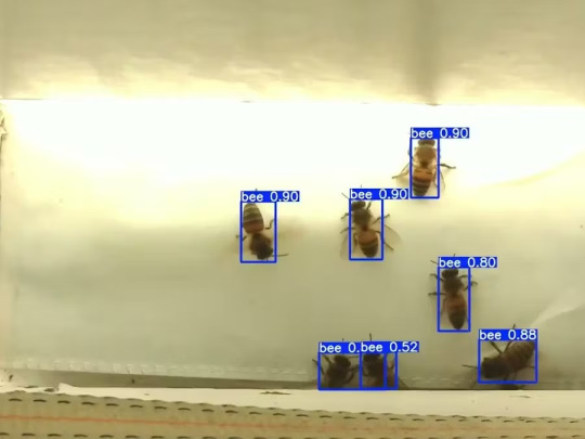
Mixtile Edge 2 Kit– AI based bee detection and tracking
Here I describe usage of Mixtile Edge 2 Kit in agriculture, bee detection, which can be essential for health and survival of bees.
Story
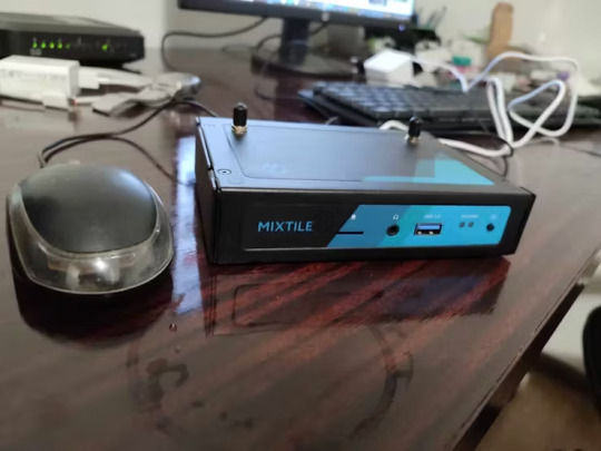
Mixtile is professional IoT hardware solution provider specialized in Linux and Android-based embedded systems.Mixtile Edge 2 Kit is high-performance ARM single board computer. It comes in variants of 2GB of LPDDR4 DRAM and 16GB eMMC Flash storage, or 4GB of LPDDR4 DRAM and 32GB eMMC Flash storage. This single board computer comes with preinstalled Android 11, and it runs Ubuntu Linux operating system in Android container. It comes with large connectivity options (Bluetooth, 4G/5G Cellular, GPS, and Lora, Zigbee and Z-Wave). For those, you will need module, but it comes with default onboard Wi-Fi connectivity, Gigabit Ethernet Port (RJ45) and Serial Port (RS-485). Because it comes with RS-485 port, which is industrial standard, and it comes within a strong metal case, it seems to me that it can be really used in industrial projects. I used official Raspberry Pi 5 power supply in order to power up my Mixtile Edge 2 Kit.So, an idea came to me why not to use it in agriculture, bee detection, which can be essential for health and survival of bees.This project will cover setting up Mixtile Edge 2 Kit, and custom photo dataset form video in order to train custom YOLOv5 bee detection model. YOLOv5 models must be trained on labelled data in order to learn classes of objects in that data.I gathered data from video and trained model on my PC.To train a model, I used python and typed in command line:
python train.py --img 640 --batch 16 --epochs 3 --data coco128.yaml --weights best.pt
My training results are summarized in the following table:
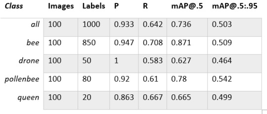
Training results
From this table you can see that images are divided into 4 detection classes:
Bee
Drone
Pollenbee
Queen
Example for each class is summarized in a table below:

Bee classes
1. Getting started
First, I will write about software part of the project, and later on steps of starting the recognition.
1.1 What is YOLOv5?
If you have been in the field of machine learning and deep learning for some time now, there is a high chance that you have already heard about YOLO. YOLO is short for You Only Look Once. It is a family of single-stage deep learning-based object detectors. It was written using Python language, and the framework used is PyTorch.
To ease control, I connected usb mouse to the one of three Mixtile Edge 2 Kit USB3 port. I used Ubuntu Linux for this project. Ubuntu on container is installed in Android system of Mixtile Edge 2 Kit by default. When you boot Mixtile Edge 2 Kit, you get Android OS. Since I wanted to access Edge 2 Kit remotely, and get easier control, I installed droidVNC server from this link:
It is an Android VNC server using Android 5+ APIs. It does not require root access.
I started the VNC server, connected with VNC Viewer and I got the following Android 11 screen:

Android 11
After that, I installed SimpleSSHD from this link:
SimpleSSHD is a SSH server Android app, based on Dropbear.It allows user access (user ssh) or full root access (by setting the login shell to /system/xbin/su) (if root is allowed).
After I installed SSH server, I connected to it via putty SSH terminal. Username and Password are root/root.
Com.hubware.ubuntu is ubuntu on a container and we are connected to it immidiately.
Now we are going to install required software.
First, you will need to upgrade Ubuntu by typing in the command: apt-get upgrade.
Second, I installed python by typing: apt-get install python.
You will also need pip, the package installer for Python.
2. Installing the YOLOv5 Environment
To start off we first clone the YOLOv5 repository and install dependencies. This will set up our programming environment to be ready to running object detection training and inference commands.
Install git: apt-get install git
Clone YOLOv5 repository:
git clone https://github.com/ultralytics/yolov5
Move to YOLOv5 folder:
cd yolov5
Install dependencies:
pip install -r requirements.txt
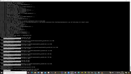
Wait some time to download and install all requirement packages, I waited 25 minutes, because there are a lot of python packages to install besides YOLOv5. YOLOv5 needs numpy package, scipy, OpenCV, etc.
The putty connection and installation process looks like below:
I transferred my model best.pt to the yolov5 installation folder via SCP, with MobaXterm.
You can simply download my model immidiate by typing:
wget https://github.com/sdizdarevic/beedetectionyolov5/raw/main/best.pt
Also, download original video by typing:
wget https://sdizdarevic.typepad.com/cr/bees-orig.mp4
Now, the final step is detection, and we are interested in the “result” content video.
python3 detect.py --weights best.pt --source bees-orig.mp4
The process of detection looks like below:

In the last lines from last picture we can see the detected number of bees at any point in time.
The summarized short steps to follow are below:
git clone https://github.com/ultralytics/yolov5
cd yolov5
pip install -r requirements.txt
wget https://github.com/sdizdarevic/beedetectionyolov5/raw/main/best.pt
wget https://sdizdarevic.typepad.com/cr/bees-orig.mp4
python3 detect.py --weights best.pt --source
Demonstrated videos are on urls with detection finished completely on Mixtile Edge 2 Kit. Output video is in folder runs/detect/exp2.
Original video:
youtube
Result video:
youtube
Last, but not less important: If you want to safely turn off your Mixtile Edge 2 Kit, I recommend you to install Shutdown (no Root) application: https://play.google.com/store/apps/details?id=com.samiadom.Shutdown&hl=en.
3.Conclusion:
After testing I found out that the Mixtile Edge 2 Kit is designed with wide range of applications, from industrial applications, IOT devices, smart home automation, to more than capable AI and edge detection. It is low powered device, with a lot of built-in connectivity options.
I would like to thank amazing Mixtile people for creating this amazing peace of hardware and especially for sending me the Mixtile Edge 2 Kit. Also, Mixtile nurtures the open source values and software, and I believe more people and companies will be involved in making projects with this board.
All in all, I recommend this board for implementing types of projects I described here.
0 notes
Photo

Will Whang's FourThirdsEye Puts a Sony IMX294 Sensor on Your Raspberry Pi 5 or Compute Module 4
0 notes
Text
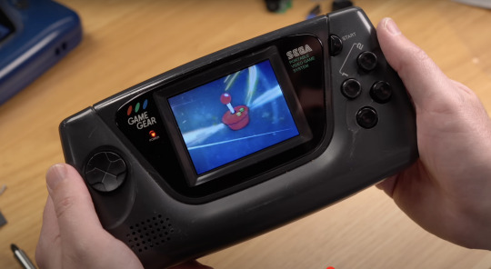
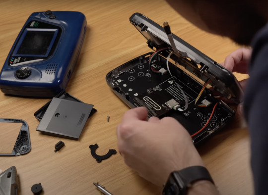
Our Compute Module 4 isn’t just for industrial applications. Turns out it can also resurrect childhood memories. Jeff Geerling blended sentimentality and innovation by sneaking one inside an old SEGA Game Gear to bring it, and his memories of Christmases past, back to life.
youtube
I do so like Jeff’s build video for the extra effort he put into finding the *exact* TV commercials that made us absolutely resolute that we must get a Game Gear for Christmas
Though the Game Gear was often seen as the poor cousin of the Game Boy, it still offered approximately 390 games. Not enough to satiate some modern gamers’ desires, however, so Jeff found a thoroughly 21st-century workaround.
RetroPie to the rescue
Compute Module 4 is running RetroPie inside a salvaged Game Gear handset, giving the user access to as many classic games as the innards of their machine will allow. Jeff explains in his build video that he could have used a Raspberry Pi Zero 2 W or a 3A+, which would draw less power but wouldn’t be quite as fast.
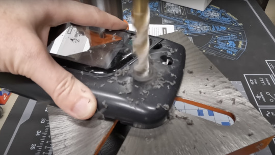
Custom modding kit
Jeff found a used, broken Game Gear handset online, and turned to John Maddison’s Zega Mame Boy, a Game Gear modding kit designed for use with Raspberry Pi, to help with the transformation. A smaller, more powerful audio board stepped in to improve the Game Gear’s sound. He also got a new screen and some fresh buttons from Hand Held Legend to disguise the battle scars from hours and hours of use in the handset’s previous life. I know from personal experience that your screen will get scratched if you throw your Game Boy at the wall every time you fail to complete the Bowser’s Castle level in Super Mario Bros.
The Zega Mame Boy PCB slips straight into the Game Gear’s shell
With more time, Jeff would have addressed the battery life issue and swapped out the device’s original battery for something a bit punchier.
JEFF YOUR FINGERS
Anyone got a time machine?
Using Raspberry Pi to bridge the gap between past and present is one of our favourite things. If 2003-me had known that 2024-me could use my hot pink Game Boy Mini to play any retro game I wanted, I would’ve kept hold of it. Alas, off to eBay I go to source another one.
#youtube#sega#game gear#sega game gear#compute module 4#jeff geerling#game news#handheld#console#sega console
0 notes