#Tracking Roller Assembly with Web Guiding System
Explore tagged Tumblr posts
Visit Tumblr Blog
Explore Tumblr blogs with no restrictions, modern design and the best experience.
Last Seen Tumblr Blogs


Fun Fact
There were a total of 171.5 billion posts on Tumblr in 2019.
Link

Krishna Engineering Works manufacturers, exporters & suppliers Tracking Roller Assembly with Web Guiding System & Bow Roll. We provide an accurate Tracking Assembly system with Web Guiding Unit or Edge Guiding Unit Consisting of two rectangular steel tubing frames. One is stationary, the other is movable. it is supported in a nyalguide sliding block and arcuate bar system and has an idler roller at either end. Tracking Roller Assembly are manufactured paying attention to the exact requirements of our customers.
#Tracking Roller Assembly#Tracking Roller Assembly with Web Guiding System#Automatic Guiding System#Web Guiding System Manufacturers#Web Aligner System#Hydraulic Power Pack#Web Guiding System#Web Guide System#Web Aligner
5 notes
·
View notes
Link

KEW is the most leading manufacturer for Tracking Roller Assembly with Web Guide System, Web Aligner it consists of two rectangular steel tubing frames. One is stationary, the other is movable. We specialize in manufacturing quality Tracking Roller Assembly. For More information visit our website: kew.net.in & Contact us: [email protected]
#Tracking Roller Assembly#Tracking Roller Assembly with Web Guiding System#Tracking Roller Assembly Manufacturer#Tracking Roller Assembly Supplier#Web Aligner#Web Aligner System
1 note
·
View note
Link

Manufacturer of Tracking Roller Assembly with Web Guiding System with TRA in A-shaped path with reversing direction through TRA in a configuration. KEW is the most leading manufacturer of the Tracking Roller Assembly with a Web Guiding System. Heavy-duty Tracking Roller Assembly with Web Guiding System with high-quality equipment like rollers, air pipe, oil pipe, adjuster, sensor, and many more. Web Guiding, Web Guiding Unit, Web Guiding System, Web Guiding Equipment, Tracking Roller Assembly, Web Guide Control System, Web Guiding System Manufacturers, Hydraulic Web Guide Control System, Tracking Roller Assembly with Web Guiding System.
#Web Guiding#Web Guiding Unit#Web Guiding System#Web Guiding Equipment#Tracking Roller Assembly#Web Guide Control System#Web Guiding System Manufacturers#Hydraulic Web Guide Control System#Tracking Roller Assembly with Web Guiding System
0 notes
Link
Web Aligner for Liner Rewinder Machine manufacturer. Web Aligner for Liner Rewinder Machine, Web Guiding Systems are used to automatically guide all type of all type of flexible material of any width, under any load, at any seed. Web Guiding Systems which serves various application for all type of flexible printing, packaging & converting machineries. Also Manufacturer of Web Guiding Systems available with Edge Guiding, aligner, Tracking Roller Assembly etc..
#Web Aligner for Liner Rewinder Machine#Aligner Unit#Web Guiding System#Web Guide System#Web Guide Systems#Web Guide#Web Guides#Web Guiding Unit#Web Guiding Units#Web Guide Unit#Web Guide Units
1 note
·
View note
Link
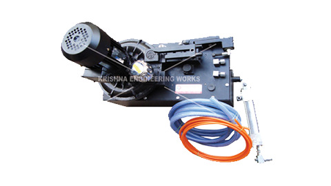
Hydraulic Power Pack for Rotary Machine, Web Guiding Systems are used to automatically guide all type of all type of flexible material of any width, under any load, at any seed. Web Guiding Systems which serves various application for all type of flexible printing, packaging & converting machinery like slitter rewinder machine and doctoring rewinding machine. Web Guiding Systems available with Edge Guiding, aligner, Tracking Roller Assembly etc., Hydraulic Equipment, Hydraulic Power Pack, hydraulic power pack price india, hydraulic power pack pdf, 2 hp hydraulic power pack price, hydraulic power pack Wikipedia, hydraulic power pack India, hydraulic power pack uses, 5 hp hydraulic power pack price, hydraulic power pack specification, Hydraulic Power Pack Manufacturer
#Hydraulic Equipment#Hydraulic Power Pack#hydraulic power pack Wikipedia#hydraulic power pack uses#5 hp hydraulic power pack price
0 notes
Text
Web Guides Used For Edge Postition Control
A variably baggy or cambered web will cause the web to track toward the variably tighter side. Variabilities in roller traction or drag can cause a steering of the web. Changes in tension will cause changes in how straight the web travels downstream. At zero tension, edge position control is essentially lost. However, there are other edge movement factors which include nip roller draw variations, aerodynamics and so on. Web guides are used to bring the edge or center of a web to a specific CD position. The guide location may be at an unwind to get the web started down through a machine in a consistent position, at an intermediate location, or at the winder to improve roll edge quality. The accuracy demands for the guide may vary from merely keeping the web on the rollers, to minimizing trim loss, to registering several print colors to within a couple of mils. Guides may be either active or passive.
What is an acceleration offset
One of the most troublesome of the edge position excursions is known variously as the acceleration or ramp offset. Here, the web moves sideways when machine speed is increased or decreased. Usually the rate of movement is most severe at the top and bottom of the speed change rather than on the speed ramp itself. Unfortunately, the term “acceleration offset” belies the true nature of the cause of the edge movement. Indeed, the web does not even know how fast it is moving.
In the case of absolute traction, the web will conform to the Normal Entry law on all rollers, including the one that is misaligned. Note how the web moves over as the result of this misalignment. In the case of pure flotation, however, the web is not steered by the ‘roller’ and, thus, passes straight through the machine. The case of sliding is intermediate in that there is a small offsetting of the web.
Thus, every roller or element that touches the web also steers the web. However, if the roller is stationary and the state of traction constant, the path of the web will remain constant. That is not to imply straight. Obviously the web will snake through the machine in conformance to web handling laws.
However, if the web changes from full to partial tracking the path of the web will change slightly in response. This change in traction will be subtle and not easily picked up by conventional observations and measurements. Nonetheless, it will cause the web to move in response.
While there are many ways the state of traction can change, the most common is due to a tension change on a lightly wrapped roller. This means that if our drive allows tension variations, the web might shift slightly on some of the rollers. Furthermore, the condition which is most difficult to hold tensions is during a speed change.
Thus, as we not see, the acceleration offset is not due to the speed or speed change itself, but rather due to tension variations that can and will accompany the speed change. Our first efforts should then be to tune the drive so that tension is held well at sensors (load cells) as well as elsewhere where there are no sensors. Sometimes tension is held well only at the drive points or sensors, but not elsewhere because the web might be pulling against excessive roller inertia or drag.
However, we can also expect to reduce the severity of the offset if we reduce roller misalignment or other geometrical problems. The surest way to do this is through optical alignment of every roller in the line because even the lowly idler is as capable of shifting the web as any of major process rollers. However, sometimes it is not the roller, but rather an airfloat oven, that is steering the web.
If you want to keep your web as uniform, flat, and baggy free as possible. This is because the web with profile troubles will merely exaggerate the difficulties discussed here. Only when material and machine are made true will edges run consistent.
How does the web guide system work?
Active web guide system is composed of a sensor, an actuator, and a controller, which is a high-efficiency edge position control. The sensor can be any detector which can reliably pick up the edges of a web. The most common are pneumatic (nonporous webs), photoelectric (opaque webs), or paddies (thick webs). The web must be flat (free of curl) and stable (free of flutter) through the edge sensor. For this and other reasons, the sensor is often placed near a roller. If two sensors are used, the web could be guided to the front edge, back edge, or center.
The output of the sensor goes to a controller which outputs a movement command to the actuator. If the gain of the controller is too low, the response of the guide will be sluggish and slow to correct. If the gain of the controller is too high, the guide will be hot but overshoot, or may even be unstable. The actuator which moves the guide mechanism may be a stepper motor and ballscrew for smaller assemblies or a hydraulic cylinder for larger assembli`es. The actuator and framework must be stiff for responsive operation.
For more professsional knowledge, please visit the page of web guide system articles.
0 notes
Text
Detailed guided on PCB Panel utilization
The PCB Panel benefit
A composite of printed circuit boards, i.e. Printed circuit boards that are not isolated are firmly fixed and the assembly of the printed circuit board also belongs to it, is generally taken as a printed circuit board benefit. The beauty of the layout designs must be the design of the printed circuit board use, in order to be able to use the printed circuit boards at optimal costs and stocks and configurations. The influence of the PCB benefits on the manufacturing costs of the PCB and the cost of assembly. The manufacturing costs of printed circuit boards become clear through the PCB panel inspection control, which is the right regulation of the production panel with the control used by the printed circuit boards.
In the constructed example in Figure 1, the load on panel A (6-fold use) is approx. 50% and the load on panel B (4-fold use) is approx. 70%. With suitable individual printed circuit boards and by cleverly dimensioning the panel and arranging the panels appropriately, panel utilization of up to 85% can be achieved.
Figure 1:PCB Panel utilization

Figure 2 shows the relative cost contributions in the production of printed circuit boards for a standard printed circuit board (100 * 160mm, 8 holes per cm2, 127µm track width/distance, surface: HAL) depending on the number of layers. Essentially, only the costs for drilling, cutting (scoring or milling), the electrical test, packaging and for some material components are directly dependent on the number of printed circuit boards that can be accommodated on a panel. The remaining cost components are independent of the number of printed circuit boards per panel.
Cost components in the circuit board production
Figure 2: Cost components in the production of printed circuit boards
Generally speaking, it can be stated that approx. 70% to 80% of the PCB manufacturing costs are to be regarded as fixed costs, i.e. they are independent of the number of PCBs per panel. For the configurations shown in Figure 1, this means that the 8 circuit boards (Panel B) can be manufactured and purchased almost at the total price of 6 circuit boards (Panel A). The optimal benefit size in terms of manufacturing costs is certainly dependent on the manufacturer. However, considering the commercially available panel cuts of 610 * 530mm or 1070 * 1225mm (standard sheet format) and the mounting margins and spacing required for the manufacturing process, the PCB panel utilization and thus the price formation in the PCB manufacturing for many PCB manufacturers is an optimal benefit size of approx. 245 * 285mm.
The assembly process has cost components that are directly related to the number of components per benefit and thus to the number of printed circuit boards per benefit, such as: Consumption of solder, direct SMD or THD assembly costs per component and AOI cost per component. The costs for packaging the circuit boards, an electrical function test and for separating the circuit boards from the panel are proportional to the number of circuit boards in the panel. Other cost components are almost independent of the number of printed circuit boards in use or the number of components on the printed circuit board:
Throughput time of the benefit in the soldering system, Time for paste printing, The placement machine is idle during retraction/extension or change of use. Assembly costs for PCBs benefit
Figure 3: PCB assembly costs
This reduces the processing costs in the PCB assembly for a benefit with an increasing number of PCBs in the benefit, as shown in principle in Figure 3. The following briefly examines whether maximizing the number of printed circuit boards in terms of use is always technologically sensible.
PCB Benefit Dimensions
The maximum benefit size or PCB size varies depending on the PCB manufacturer and technical equipment. Based on the standard PCB panel size cut 610 * 530mm, which is often processed, there are maximum dimensions of approx. 570 * 490mm for many manufacturers. In electronics production at CAD-UL, the maximum dimensions are specified by the machines used, provided that it is to be carried out completely mechanically:
Paste printer 600 * 600mm SMD pick and place machine 400 * 550mm Vapor phase soldering system 550 * 600mm
The following reasons speak against the processing of benefits with the maximum dimensions:
As PCB panel size increases, this also loses stability, which can also be seen depending on the PCB thickness. There is a risk that the connection points between the circuit boards break due to improper handling.
The base materials for printed circuit boards can shrink or stretch during the printed circuit board manufacturing process (dimensional stability). In addition, there are of course manufacturing tolerances in the production process of the circuit board, which can lead to an offset of copper structuring, to drilling and contour of the circuit board and to an offset from layer to layer. With a lot of know-how and by adapting the production data, the PCB manufacturers manage to keep the effects to a minimum. With very large circuit boards or with large benefits where components with small pads, e.g. B. 0.4mm pitch, placed far apart, this can lead to borderline differences between the x, y positions of the pads on the circuit boards and the associated breakouts of the steel stencils for paste printing.
Additional measures must be taken to prevent the bending of the PCB panels during transport in the transport devices, during paste printing, in the placement system and during the soldering process. The bending can lead to faulty paste printing or mechanical stress on the solder joints. In the manufacture of printed circuit boards, problems with the final inspection and the electrical test arise with increasing dimensions.
If there is a requirement not to allow failure circuit boards in the panel, maximizing the number of circuit boards in the panel can lead to a significant loss in yield and thus to a price increase for the single circuit board.
Connection of the circuit boards and benefit separation
The design of the benefits must be reconsidered and specified during the PCB layout phase so that there are no surprises later during the assembly process. Basically, a decision for a procedure must be made: scoring, milling or a combination of both. The position and orientation of the components relative to the scratching trench or the milling ridges must be selected so that the force applied when the panels are separated is as small as possible. The copper must be set back sufficiently from the scoring trenches or perforation holes for the burrs in order to avoid water exposure. Ultimately, the layout designer is also responsible for sufficient stability of use during all machining processes and for the joint and coordinated optimization of the manufacturing and assembly costs of the printed circuit board.
Connection of printed circuit boards and benefit separation for printed circuit boards with a straight and continuous contour with a minimum of two opposite parallel sides see Figure 4 and if there are no special requirements with regard to edge roughness, the scoring or notch milling process can be used. Trenches lying one above the other are carved on both sides of the printed circuit boards. The notch angle is usually 30˚, the notch depth depends on the board thickness and the remaining core thickness is approximately 0.4mm. The scribing process is no longer useful for circuit board thicknesses greater than 2.0 mm. In order to reduce the mechanical stress when separating the printed circuit boards from the panel to a minimum, CAD-UL uses a scratch PCB panel separator with a fixed and a roller knife.
Figure 4: PCB Scoring benefits
For circuit boards with irregular contours or if there are increased demands regarding edge roughness and dimensional accuracy, see Figure 5, the circuit board contour must be milled. The diameter of the milling cutters, usually 2.0mm or 2.4mm, for edge processing should be specified because the blanking process must be set to this milling width. Bars must remain during milling in order to connect the circuit boards to one another or to the utility frame. The number, position, and width of the webs must be carefully determined depending on the use or milling benefits of the printed circuit board size and thickness, in order to be able to guarantee sufficient mechanical stability during all processing operations, as well as to separate the printed circuit boards from the use with little mechanical To be able to carry out stress on the solder joints and components. The webs can also be scratched or provided with perforation holes inside, on or outside the circuit board contour, see Figure 6, in order to be able to further reduce the stress effect when cutting.
Figure 5: PCB Milling benefits
With CAD-UL, the webs are either punched out by a pneumatically working web separator with a hook knife, or the circuit boards are separated from one another by milling. Depending on the separation process and the position of the perforation holes, sharp-edged remnants of the webs can remain on the circuit board, which can lead to injuries. These are to be removed after the separation.
Figure 6: Variants of router bars
A common feature of all depaneling processes is that the circuit board deforms at the separation points due to the mechanical action during the separation and that forces are exerted on the components and the soldering points. These can lead to component defects, in particular hairline cracks in SMD ceramic capacitors. Under certain circumstances, these defects are not immediately visible or have no effect, but only lead to malfunctions of the affected components after a long time.
Mixed benefits are defined as benefits that combine different printed circuit boards with identical layer structure and identical manufacturing technology. The motivation for this is clear, printed circuit boards are only charged once and only one paste printing stencil is required for a printed circuit board with SMD on one side. If, however, the Gerber data set provides several parts lists and several pick & place data sets for the benefit, in which reference names may be assigned more than once, these data sets must be combined with effort and risk of error by the work preparation department for electronics production in order to effectively create components shopping and to be able to effectively consider the benefits as an assembly project. Most of the time, the different printed circuit boards are installed in the device in one device and these printed circuit boards are therefore required in the same number of pieces or in a fixed number of pieces. However, since raw circuit boards already fail in use and errors can occur during the assembly of printed circuit boards, the planned quantity ratio cannot be guaranteed after the end of production. This can lead to problems, particularly with series assembly. The savings in one-off costs at the start of the project may later be expensive.
Figure 7: Mixed benefit
All those involved, the circuit board layout, the circuit board manufacturer and the circuit board assembler should carefully weigh the advantages and disadvantages of a mixed-use at the start of the project and determine an optimal procedure together.
In order to make optimal use of the space on a production panel, it is also possible to use irregularly shaped printed circuit boards, e.g. L-shaped or T-shaped, to be arranged rotated to each other on a PCB panel with 90 mit or 180˚. However, since printed circuit boards have preferred directions for paste printing and wave soldering, it should be checked whether this procedure also guarantees an optimal assembly process.
Last but not least, a printed circuit board that is to be produced and assembled individually, e.g. Components placed too close to the edge or where there is no more space for fiducial brands and which therefore must be provided with a receiving edge on at least two opposite sides are referred to as benefits.
Please do not hesitate to contact us if you have any questions about the design of the benefits or support in the creation of the benefits. Our employees in the areas of PCB layout and work preparation are always at your side with advice and action.
Dimensions of single circuit board and delivery benefits
Single PCB
Please select this option if your circuit board consists of a single circuit pattern. We always mill individual circuit boards. The circuit board may contain internal cutouts as long as it does not separate the circuit diagram. Otherwise, we speak of a PCB benefit.
If your PCB is smaller than 30x15mm, please put it in a delivery benefit. For this, we offer you the option “PCB Delivery benefit with online configuration”.
Delivery benefits
Delivery benefit from file or plan:
The same applies to multi-use if you want to order different conductor patterns in one use.
Delivery benefits with online configuration:
Do you have the data of a single circuit board and no benefit drawing, but would like to have your circuit board in the delivery benefit? Then simply tell us in the configurator how we can design the benefits. If you need predetermined breaking holes, please bring them into the single image in advance.
You can find more on the definition of a delivery benefit in our tutorial!
Registration marks in the edge of the sheet
On request, we can introduce registration marks in the delivery area of your printed circuit boards. Place it like 3 copper pads with a diameter of 1.00 mm in the middle of the edge of the PCB panel. In the solder mask, these are exempted with 2.00 mm.
Bad parts in the delivery benefit
In the delivery benefit, it can happen that individual circuit boards are struck out by our quality assurance if the quality does not meet our standard. We never paint more than 50% of the printed circuit boards on a delivery benefit. We also fill in the missing number of items by sending more delivery benefits than you ordered. So that you always get at least the desired number at the end.
Features of flex PCB
A circumferential edge of ≥ 7.50 mm is absolutely necessary. If there is a copper-free surface, the delivery benefit edge is always rostered onto the top and bottom. This prevents the PCB from warping. The edge of the delivery benefit is always coated on both sides with flex lacquer (even with a 1F structure).
General information on dimensions
The size of your circuit board is determined by the measurement from center contour to center contour. We, therefore, recommend using a contour line of 200 µm to avoid ambiguities.
At Moko Technology, your printed circuit boards can be machined using notches, milling or a combination of notches and milling. We carry out milled PCBs.
When milling a multiple-use, your printed circuit board remains connected in the benefit by means of retaining bars. The standard cutters are 1.60mm, 2.00mm or 2.40mm.
When notching, MOKO Technology place your printed circuit boards in the delivery benefit.
0 notes
Link

We are Specialised of Web Guiding System for Rotogravure Printing Machine, high quality equipment Web Aligner Unit, Web Guide System, Edge Guiding System. Web Guiding System for Rotogravure Printing Machine are used to automatically guide all type of flexible material of any width, under any load, at any seed. Web Guiding Systems which serves various application for all type of flexible printing, packaging & converting machineries. Web Guiding Systems available with Edge Guiding System, Web aligner System, Tracking Roller Assembly etc.
#Web Guiding System#Web Guiding System manufacturer#Rotogravure Printing Machine#Rotogravure Printing Machines#Web Guide System#Web Guide System manufacturer#Web Guide Systems#Web Guide Systems manufacturer#Web Aligner#Web Aligner System#Web Aligner Unit#Web Guiding unit#Web Guide Unit#Hydraulic Power Pack#Hydraulic Power Pack system#Hydraulic Power Pack Unit
0 notes
Link
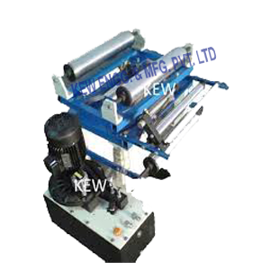
High-quality Rewinder Machine Manufacturer, Rewinding Machine, all type of high-speed Rewinder Machine with Web Aligner for different type of material and industry. All types of Rewinder Machine with Web Aligner for all types of Roto Gravure Printing Machine, Lamination, Coating Machine, Slitting Rewinding Machine, Extruder Machine, Textile Machine, Tyre Machine, etc. The Rewinder Machine is available with: Web Aligner System, Mechanical or Pneumatic Brake, Tension Control System, Line Guide System, Rollers, Safety Chucks, Bow Roller, Unwinder Drive & Control Panel (Optional), Shaft less Unwinder Unit. Rubber Roller Manufacturer, Rewinder Unwinder Manufacturer, Slitting Machine, Slitting Rewinder Machine Manufacturer in India.
#Winder Rewinder#Rewinder Machine#Rewinding Machine#Slitting Machine#Slitting Rewinding Machine#Slitter Rewinder Machine Manufacturer#Roto Gravure Printing#Printing Machine#Extruder Machine#Textile Machine#Line Guide System#Tracking Rollers Assembly#Bow Roller#Unwinder Drive#Rubber Roller Manufacturer#Coating Machine#tyre machine#Web Aligner System
2 notes
·
View notes
Link

KEW ENGG. & MFG. PVT. LTD. is the most leading manufacturer for Tracking Roller Assembly with Web Guiding System. it consists of two rectangular steel tubing frames. Our Tracking Roller Assembly with Web Guiding System for various industries running with accurate performance. We provide an accurate Tracking Roller Assembly with Web Guiding System or Edge Guiding Unit Consisting of two rectangular steel tubing frames.
#Tracking Roller Assembly with Web Guiding System#Web Guiding System#Web Guiding System Manufacturers#Hydraulic Web Guide Control System#Web Aligner System#Web Edge Guide System#Web Guiding Machine#Web Aligner#Web Guiding Trolleys#Web Guiding Unit#Hydro Technology Web Guiding System#Automatic Guiding System Manufacturer#Automatic Web Guiding System#Hydro Pneumo Web Aligner System#Mild Steel Web Aligner System
1 note
·
View note
Link

High performance and accurate line guiding system, Web Aligner, Web Guiding System Manufacturer with International Standards, Web Guiding System Supplier. Web Guiding Systems which serves various application for all type of flexible printing, packaging & converting machineries. Web Guiding Systems available with Edge Guiding, aligner, Tracking Roller Assembly, Digital Edge Guide System, Line Guide System, etc. We have designed web guiding system for machines, slitter rewinder machine manufacturer with web aligner unit.
#Web Guiding#Web Guiding System#Web Guiding System Manufacturer#Web Aligner System#Web Aligner#Web Aligner Manufacturer#Web Guide System#Web guide system manufacturer#Web Aligner Unit#Web Guiding Unit#Web Guide Unit#Web Guide Unit Manufacturer
2 notes
·
View notes
Link

Web Guiding System for Lamination Machine, Hydraulic Power Pack for Lamination Machine are used to automatically guide all type of Lamination Machine for laminating material, flexible material of any width, under any load, at any seed. Web Guiding Systems which serves various applications for all types of flexible printing, packaging & converting machinery like rotogravure printing machines. Web Guiding System for Lamination Machine available with Edge Guiding, aligner, Tracking Roller Assembly, etc. Hydraulic Power Pack, Lamination Machine, Web Guide System, Hydraulic Power Pack for Lamination Machine, Lamination Machine Price, Hydraulic Power Unit, Best Lamination Machine, Thermal Lamination Machine, Industrial Laminating Machine, Paper Lamination Machine Price, Roll to Roll Lamination Machine, Automatic Lamination Machine, Hydraulic Power Pack Price, Electric Hydraulic Power Pack, Hydraulic Power Pack Manufacturers, Heavy Duty Laminating Machine, Plastic Lamination Machine, 12 Volt Hydraulic Power Unit, A4 Laminating Machine, Hydraulic Power Packs for Sale
#Hydraulic Power Pack#Lamination Machine#Web Guide System#Hydraulic Power Pack for Lamination Machine#Lamination Machine Price#Hydraulic Power Unit#Best Lamination Machine#Thermal Lamination Machine#Industrial Laminating Machine#Paper Lamination Machine Price#Roll to Roll Lamination Machine#Automatic Lamination Machine#Hydraulic Power Pack Price#Electric Hydraulic Power Pack#Hydraulic Power Pack Manufacturers#Heavy Duty Laminating Machine#Plastic Lamination Machine#12 Volt Hydraulic Power Unit#A4 Laminating Machine#Hydraulic Power Packs for Sale#Lamination Machine Price Amazon
0 notes
Link

KEW ENGG. MFG. PVT. LTD. is a leading manufacturer of Tracking Roller Assembly. We provide an accurate Tracking Assembly system with Web Guiding Unit or Edge Guiding Unit Consisting of two rectangular steel tubing frames. It is insensitive to attitude and can even be mounted upside down. Solidly supported on all four corners by nylaguide bearings, Tracking Roller Assembly with Web Guiding System not subject to deflections caused by cantilever stresses.
#Tracking Roller Assembly with Web Guiding System#Web guiding system#Web guiding system manufacturers#Web guiding#Web aligner system#Tracking Roller Assembly#Web Aligner#Rewinding Machine with Web Guiding System#Edge Guiding System
1 note
·
View note
Link

We are thorough industrial knowledge, we are involved in manufacturing, providing and exporting a variety of Tracking Roller Assembly. These products are manufactured paying attention to the exact requirements of our customers. It consists of two rectangular steel tubing frames. One is stationary, the other is movable. it is supported in a nyalguide sliding block and arcuate bar system, and has ab idler roller at either end. Web Guide System Manufacturer, Tracking Roll Assembly, Web Guiding System.
#Tracking Roller Assembly#Tracking Roll Assembly#Tracking Roller Assembly Manufacturer#Tracking Rollers Assembly#Tracking Roll Assembly Manufacturer#Web Guide System#Web Guide Systems#Web Guiding System#Web Guiding Systems#Web Guiding System Manufacturer#Web Guiding#Web Aligner#Web Aligners#Web Aligner system
2 notes
·
View notes
Link
We are most leading manufacturer for Tracking Roller Assembly With Web Guide System, Web Aligner, Web Guiding System, Pivot Tracking Assembly, Tracking Roller Assemblies it consists of two rectangular steel tubing frames it consists of two rectangular steel tubing frames. One is stationary, the other is movable. it is supported in a nyalguide sliding block and arcuate bar system, and has ab idler roller at either end. Also, Tracking Roller Assembly with heavy duty and accurate for different industries and machinery.
#Tracking Roller Assembly#Web Guide System#Web Guide System manufacturer#Web Guiding System#Web Guiding System Manufacturer#Web Aligner#Web Aligner System#Web Aligner Unit#Web Guiding Unit
0 notes
Link
Web Aligner for Plastic Processing Machine, Web Guiding Systems are used to automatically guide all type of of flexible printing, packaging converting machinery. Web Guiding Systems which serves various application for all type of flexible printing, packaging & converting machineries. web guiding system for plastic processing machine available with Edge Guiding, aligner, Tracking Roller Assembly etc. For more information visit our website: krishnaengineeringworks.com

#Web Aligner for Plastic Processing Machine#Web Guiding System#web guiding system for plastic processing machine#Hydro – Pneumo Web Aligner#Hydraulic Power Pack Unit#Textile Processing Machine#web guiding system manufacturers#web guiding
5 notes
·
View notes