#Ultrasonic Level Sensor
Explore tagged Tumblr posts
Visit Tumblr Blog
Explore Tumblr blogs with no restrictions, modern design and the best experience.
Last Seen Tumblr Blogs


Fun Fact
Hackers stole 65M passwords from Tumblr in 2013.
Text

0 notes
Text
How to Choose the Right Tank Level Gauge for Your Water Storage System
A tank level gauge and water tank gauge are essential tools for monitoring water levels in storage systems. Whether for residential, agricultural, or industrial use, choosing the right gauge ensures efficient water management, prevents overflows, and avoids shortages. With various options available, selecting the ideal gauge requires careful consideration of several factors. This guide will help you understand how to choose the best tank level gauge and water tank gauge for your needs.
Understanding Tank Level Gauges
A tank level gauge is a device used to measure and display the water level inside a storage tank. These gauges help users track water levels in real-time, ensuring proper water usage and refilling schedules. Water tank gauges come in different types, including mechanical, electronic, and ultrasonic models.

Types of Tank Level Gauges
Mechanical Tank Level Gauges
Use float systems to indicate water levels.
Reliable, durable, and require minimal maintenance.
Ideal for large water storage tanks in rural and industrial settings.
Electronic Tank Level Gauges
Use sensors and digital displays to show precise water levels.
Some models offer wireless connectivity for remote monitoring.
Best suited for high-tech applications and smart water management.
Ultrasonic Tank Level Gauges
Utilize ultrasonic waves to measure water levels without physical contact.
Highly accurate and suitable for hazardous or hard-to-reach tanks.
Recommended for industrial applications and automated water systems.
Key Factors to Consider When Choosing a Tank Level Gauge
1. Tank Size and Capacity
Larger tanks require gauges with higher measurement ranges.
Ensure the gauge is compatible with your tank’s height and volume.
2. Type of Water Storage System
For underground tanks, electronic or ultrasonic gauges provide better readings.
Overhead tanks can utilize mechanical or float-type gauges.
3. Accuracy and Precision
Digital and ultrasonic gauges offer precise readings.
Mechanical gauges provide approximate water levels but are cost-effective.
4. Ease of Installation and Maintenance
Choose a gauge that is easy to install and does not require frequent calibration.
Wireless and digital gauges may require periodic battery replacements or software updates.
5. Durability and Environmental Resistance
Consider materials resistant to corrosion, rust, and extreme weather conditions.
For outdoor tanks, ensure the gauge can withstand UV exposure and temperature fluctuations.

6. Budget and Cost Considerations
Mechanical gauges are more affordable with lower maintenance costs.
Digital and ultrasonic models may have higher upfront costs but offer long-term efficiency.
7. Remote Monitoring and Smart Features
Some modern gauges come with smartphone apps and IoT integration.
Ideal for industries and remote locations where regular manual checks are impractical.
Why Choose Nikeson’s Tank Level Gauges?
Nikeson offers a range of high-quality tank level gauge and water tank gauge solutions tailored for various applications. Their mechanical and digital tank indicators ensure accuracy, durability, and ease of use, making them a top choice for water storage monitoring.
Conclusion
Choosing the right tank level gauge and water tank gauge depends on factors like tank size, accuracy needs, durability, and budget. Whether opting for a mechanical, digital, or ultrasonic model, selecting a reliable gauge enhances water management efficiency. Explore Nikeson’s solutions for the best tank level monitoring devices to suit your specific needs.
For more information, visit Nikeson’s product page and find the perfect gauge for your water storage system today!
#tank level gauge#water tank gauge#level indicators for water tanks#rainwater level indicator#water level indicators for water tanks#level indicator water tank#water level indicator for water tank#Float & Board Level Indicator#Tank Level Indicator#ultrasonic level sensor#Ultrasonic Level Transmitter#water level gauge#water level staff gauge
0 notes
Text
youtube
Liquid Level Indicator Using ULN2003
A water level indicator detects and indicates the level of water in an overhead tank and relays the information back to a control panel to indicate whether the tank has a high or low water level. In this tutorial, I am going to use the ULN2003 IC to create a simple, inexpensive water level indicator. Using this circuit you can easily control the wastage of water and electricity. Watch this video, for detailed step by step instructions on how to build this circuit and to know how this circuit works. Towards the end of the video I will also discuss whether its really worth building this circuit.
3 notes
·
View notes
Text
The Advantages of Pinnacle's Regular Monitoring Services
Accurate and reliable well measurement is essential when it comes to controlling groundwater resources, either for residential, commercial, or industrial use. Pinnacle's regular monitoring services provide a complete solution to make sure your well water levels are regularly measured and controlled. Through this blog, we'll discuss the advantages of Pinnacle's services and how it can assist in controlling your well water.
Understanding Well Measurement
What Is The Deep Well Water Level Sensor?
A deep well water level sensor is an advanced tool used to gauge the water level in deep wells with high accuracy. Deep well water level sensors are needed to monitor groundwater levels to maintain a stable and reliable water supply. Pinnacle's deep well water level sensors are the latest technology available, offering highly accurate readings to guide sound judgment on water use and management.
How is Well Depth Measured?
Measuring well depth is an important process that requires a number of tools and techniques. The conventional approach involves the use of a well depth measuring tape, which is a basic yet efficient tool used to measure the depth of a well. That said, advances in technology have brought more sophisticated tools such as well depth gauges and handheld ultrasonic level sensors. These tools provide more precise and convenient measurements, and they are thus suitable for use in both domestic and commercial contexts.
Well Water Level Sensor and Ultrasonic Water Level Controller
Pinnacle's ultrasonic water level controllers and well water level sensors are programmed to give real-time water level information. The sensors are equipped with sophisticated technology to accurately measure water levels and can be linked to automated systems to monitor the levels continuously. The ultrasonic water level controller, specifically, gives a contact-free way of measuring water levels, minimizing contamination risks and providing long-term dependability.
Pinnacle's Well Measurement Solutions
Pinnacle provides a variety of well measurement solutions that are specifically designed to address the individual needs of our customers. If you are purchasing a home with a well or selling a home with a well, our services provide you with the correct and current information about your well water levels. Our solutions consist of Level Measurements in Groundwater Wells, Well Measurement Services, and Well Measurement Formula. Pinnacle applies sophisticated formulas and equations to accurately estimate well water levels. Our methods are statistically proven and offer consistent data for making informed decisions.
Measuring River Flow Rate
Besides the measurement of well water levels, Pinnacle also provides river flow rate measurement services. This can be especially applied in environmental monitoring and water resource management. By accurately measuring river flow rates, we can help protect and sustainably manage water resources.
Why Choose Pinnacle?
Company That Measures Well Water Levels
Pinnacle is a prominent organization specialized in measuring well water levels, which has an array of services and solutions to cater to your needs. Our specialized services are supported by years of experience and state-of-the-art technology. No matter if you want a single measurement or continuous monitoring, Pinnacle's services are tailor-made to suit your requirements.
North Georgia Well Level Testing
For individuals and businesses in North Georgia, Pinnacle offers customized well level testing services. With our local expertise and familiarity with the area, we are able to understand the specific needs and challenges of the region. If you worry about water levels in times of drought or require constant monitoring for farm use, Pinnacle is your go-to service provider.
Conclusion
Maintaining well water levels is crucial for a secure and consistent supply of water. Pinnacle's ongoing monitoring services offer the instruments and expertise necessary to maintain your well water levels. From sophisticated sensors and ultrasonic controllers to total measurement solutions, Pinnacle is dedicated to assisting you in managing your groundwater resources efficiently. Whether purchasing or selling a home that features a well, or just wanting to make sure your supply of water remains level, Pinnacle can assist you. Contact us today to find out more about our services and how we can help you.
#well depth gauge#portable ultrasonic level sensor#well water level sensor#what is the deep well water level sensor?#buying a home with a well#selling a home with a well
0 notes
Text
Ultrasonic Sensors: A Comprehensive Guide
Ultrasonic sensors are devices that use ultrasonic waves, which are sound waves with frequencies higher than the audible range for humans (typically above 20,000 hertz), for various applications.
These sensors operate on the principle of sending out ultrasonic waves and measuring the time it takes for the waves to bounce back after hitting an object. This information can then be used to determine the distance or presence of the object.
Ultrasonic Sensors Working Principle
The working principle of ultrasonic sensors is based on the transmission and reception of ultrasonic waves. Here’s a step-by-step explanation of how these sensors operate:
Generation of Ultrasonic Waves:
Ultrasonic sensors consist of a transducer, typically a piezoelectric crystal, that can convert electrical energy into ultrasonic waves. When an electrical voltage is applied to the crystal, it vibrates and generates ultrasonic waves in the frequency range beyond human hearing (typically above 20,000 hertz).
Wave Emission:
The ultrasonic sensor emits a short burst of ultrasonic waves into the surrounding environment. This burst of waves travels outward from the sensor.
Wave Propagation:
The ultrasonic waves move through the air until they encounter an object in their path. The waves continue to propagate until they hit a surface.
Reflection of Ultrasonic Waves:
When the ultrasonic waves strike an object, they are reflected back towards the sensor. The reflection occurs because the ultrasonic waves encounter a change in the medium (from air to the object’s surface), causing the waves to bounce back.
Reception of Reflected Waves:
The same transducer that emitted the ultrasonic waves now acts as a receiver. It detects the reflected waves returning from the object.
Time Measurement:
The sensor measures the time it takes for the ultrasonic waves to travel from the sensor to the object and back. This time measurement is crucial for determining the distance to the object.
Distance Calculation:
Using the known speed of sound in the air, which is approximately 343 meters per second (at room temperature), the sensor calculates the distance to the object. The formula for distance (D) is given by D = (Speed of Sound × Time) / 2.
Output Signal:
The calculated distance information is then processed by the sensor’s electronics, and the output is provided in a suitable format, often as an analog voltage, digital signal, or distance reading.
These sensors work by emitting ultrasonic waves, detecting their reflections from objects, measuring the time taken for the round trip, and using this time information to calculate the distance to the objects in their detection range. This working principle is fundamental to various applications, including distance measurement, object detection, and obstacle avoidance.
Ultrasonic Sensors Pins Configurations
The pin configurations of ultrasonic sensors may vary depending on the specific model and manufacturer. However, We will discuss general overview of the typical pin configuration for a commonly used ultrasonic sensor module, like the HC-SR04. This module is widely used in hobbyist and educational projects.
The HC-SR04 ultrasonic sensor typically has four pins:
VCC (Voltage Supply):
This pin is used to provide power to the sensor. It typically requires a voltage in the range of 5V.
Trig (Trigger):
The Trig pin is used to trigger the start of the ultrasonic pulse. When a pulse of at least 10 microseconds is applied to this pin, the sensor emits an ultrasonic wave.
Echo:
The Echo pin is used to receive the ultrasonic waves that are reflected back from an object. The duration of the pulse received on this pin is proportional to the time it takes for the ultrasonic waves to travel to the object and back.
GND (Ground):
This pin is connected to the ground (0V) of the power supply.
Read More: Ultrasonic Sensors
#ultra sonic#ultrasonic sensors#ultrasonic technology#sensor technology#sensor applications#non-contact measurement#distance measurement#level measurement#flow measurement#object detection#obstacle avoidance#industrial automation#automotive industry#robotics#healthcare#home automation#smart homes#IoT#internet of things#technology#innovation#engineering#science#research#development#education#learning#acoustics#sound waves#frequency
0 notes
Text

Ultrasonic Continuous Level Sensor
SEGMEN SENSOR offers a range of high-quality ultrasonic continuous-level sensors for precise and reliable level measurement in various industrial applications. For more information, please visit https://segmensensor.com/
0 notes
Text
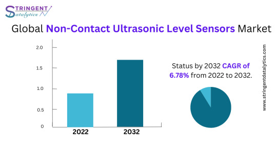
Non-Contact Ultrasonic Level Sensors Market
0 notes
Text
Revolutionize Your Operations with the KUS3000 Ultrasonic Transmitter

Are you seeking reliable and precise ultrasonic sensing technology for your industrial applications? Look no further than the KUS3000 Series Ultrasonic Transmitter, a cutting-edge solution brought to you by KC Sensor Technologies. Designed with innovation in mind, this state-of-the-art device empowers businesses like yours to take their sensing capabilities to new heights.
Unparalleled Precision and Accuracy:
The KUS3000 Series Ultrasonic Transmitter combines advanced ultrasonic technology with superior engineering, delivering unrivaled precision and accuracy in distance and level measurement. With its high-frequency sound waves, this transmitter ensures precise detection, allowing you to monitor and control fluid levels, even in the most challenging environments.
Versatile and Reliable:
Equipped with a robust construction and built-in temperature compensation, the KUS3000 Series excels in versatility and reliability. It can be seamlessly integrated into various industrial applications, including liquid storage tanks, wastewater treatment facilities, chemical processing plants, and more. Count on its rugged design to withstand harsh conditions and provide consistent, dependable performance.
Advanced Features for Enhanced Efficiency:
The KUS3000 Series Ultrasonic Transmitter offers a range of advanced features to optimize your sensing operations and enhance efficiency:
Multiple Output Options: Choose from a variety of output options, including analog current output (4-20 mA), voltage output (0-10 VDC), or Modbus RS485 communication, ensuring seamless integration with your existing systems.
Easy Installation and Configuration: With its user-friendly interface and simple installation process, the KUS3000 Series saves you time and effort. The intuitive configuration menu allows for quick parameter adjustment, minimizing downtime and maximizing productivity.
Wide Measurement Range: Experience versatility in measuring distances, as the KUS3000 Series offers a wide measurement range of up to 10 meters (32.8 feet), making it suitable for diverse applications.
Enhanced Diagnostic Capabilities: The transmitter's built-in diagnostics provide real-time monitoring and troubleshooting, enabling proactive maintenance and reducing potential downtime.
Partner with KC Sensor Technologies:
At KC Sensor Technologies, we are committed to providing our customers with the highest quality sensing solutions. Backed by extensive research and development, the KUS3000 Series Ultrasonic Transmitter represents the pinnacle of our expertise. We pride ourselves on delivering products that exceed industry standards, ensuring your satisfaction and success. Take your sensing capabilities to new heights with the KUS3000 Series Ultrasonic Transmitter. Visit our website at www.kcsensor.com to learn more about this exceptional product and discover how it can revolutionize your industrial sensing solutions. Partner with KC Sensor Technologies today and experience the power of precision.
0 notes
Text
Few Advantages of Using Sonar Tank Level Sensors
Sonar tank level sensors have become popular for monitoring and measuring tank liquid levels. These sensors are also known as ultrasonic level sensors and use ultrasonic waves to determine the level of liquids inside tanks accurately. They have numerous benefits that make them ideal for use in various applications. Here are some of the advantages that come with ultrasonic level sensors:

One of the primary benefits of sonar tank-level sensors is their accuracy. Unlike other level sensing technologies, such as mechanical float switches, sonar sensors use sound waves to determine the liquid level. This eliminates the risk of errors due to physical movement or misalignment, ensuring accurate readings every time. Additionally, sonar sensors are not affected by the type or density of the measured liquid. This makes them a versatile choice for monitoring liquids with varying properties.
Another advantage of using sonar tank level sensors is their ease of installation. Unlike other level sensing technologies, sonar sensors do not require any physical contact with the liquid. This eliminates the risk of leaks or contamination and makes installation quick and straightforward. Furthermore, sonar sensors can be installed on existing tanks without any modifications, making them an ideal choice for retrofit projects.
Sonar tank level sensors are also low-maintenance. Unlike other level sensing technologies that require regular cleaning and calibration, sonar sensors are self-cleaning and do not require regular maintenance. This saves time and resources, as well as ensures that the sensors are always providing accurate readings. Additionally, sonar sensors are rugged and durable, able to withstand harsh environments and corrosive liquids.
Another advantage of sonar tank level sensors is their remote monitoring capabilities. With the help of a data logger or tank management software, sonar sensors can be connected to a network, allowing real-time monitoring and control of tank levels from a remote location. This helps to prevent spills, ensure compliance with regulations, and improve efficiency by reducing the need for manual tank inspections.
Apart from that, sonar tank level sensors are cost-effective. They are affordable to purchase and install. They offer long-term cost savings from reduced maintenance, improved accuracy, and remote monitoring capabilities. This makes them an attractive investment. Additionally, by reducing the risk of spills and increasing efficiency, sonar sensors can help to improve an organization's environmental and safety records.
Ultrasonic level sensors for tanks provide numerous benefits for monitoring and measuring liquid levels in tanks. They are an ideal choice for a wide range of applications. If you're looking to upgrade your tank monitoring system, consider investing in a sonar tank-level sensor.
0 notes
Text
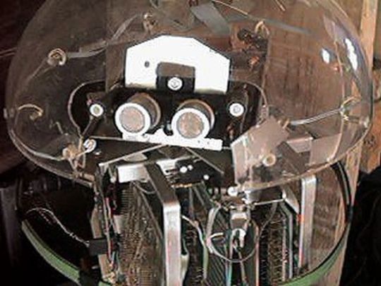
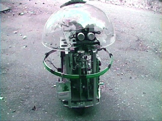
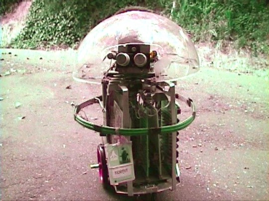
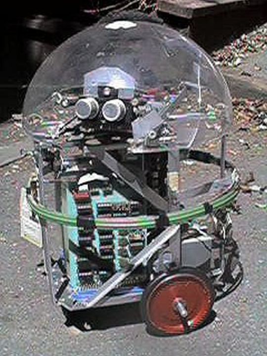
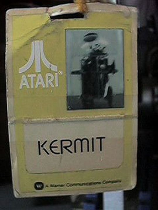
Kermit (1978), by Ron Milner and Larry Nicolson, Cyan Engineering, Atari's secret think tank in Grass Valley, CA.
"The robot was a pet project for Nolan Bushnell, then still the head of Atari and a very creative guy. Its purpose in life was as Nolan put it to "bring me a beer!" Navigation for robots was a sketchy thing at that time with lots of pioneering work at MIT but no consumer cost ideas. Nolan brought us the incredibly original idea to navigate a robot (which mostly meant knowing where it was) by means of scanning bar codes attached here and there to the baseboards in the rooms the robot was to service. Why it wasn't patented I don't know.
I had lots of fun building the R2D2 style robot about 20" tall. I liked to put mechanical and electronic things together and we had a great shop at Cyan. Its brain was one of the 6502 based single board computers-I think it was a KIM but not sure. Locomotion was two DC gear motor driven wheels and an instrumented caster-about the same rig as a modern Roomba. A rotatable turret covered with a plexiglass dome carried microphones, an IR sensor to detect people, and ultrasonic ranging sensors I built on a separate PC board. A speaker so Kermit could beep gleefully, of course.
A ring of contact-detecting burglar alarm sensing tape (green in the pictures) around Kermit's middle told the software he had hit something and should back off. The ultrasonics provided range to obstacles and to some extent direction as the turret was rotated, so we could go around things.
My pride and joy was the barcode remote scanner which was mounted on the bottom of the robot so its rotating head would be level with the barcodes on the baseboards. It had a vertical telescope tube with a beam splitter between the IR Led and the photodiode sensor and a lens to focus 2-20' away. It aimed down at a front surface mirror at 45 degree to scan horizontally. The mirror was mounted on a motor driven turret so it spun around continuously with a sensor once around to resolve the continuous angular position of the beam horizontally of course with respect to Kermit's rotational position. Unfortunately, this part of the robot did not survive the closing of our group. The barcodes I made for the prototype to detect were about 4" tall made of 3/4" reflective 3m tape on black poster board.
My programming partner on the project was Larry Nicholson, a really bright guy. He made the barcode reading work to detect not only the barcodes, but where they were angularly with respect to the robot and also their subtended angle or apparent size (all from timing of the rotation of the scanner) which was a measure of distance combined with angle from the barcode. We worked out some pretty clever math to resolve that information from two or three of the barcodes into a position and orientation of Kermit in the room. We had rented an empty room upstairs on the third floor of the Litton building to try all this out and work out the navigation. Larry and I got the basic navigation and obstacle avoidance working so Kermit could go from one place to a designated other place in the room and avoid wastebaskets placed randomly. We demonstrated it to Nolan and he was impressed.
Shortly thereafter Warner Communication who had bought Atari from Nolan kicked him out and the Kermit project was cancelled."
– Kermit The Robot Notes by Ron Milner.
64 notes
·
View notes
Note
How'd the Arduino build go? I couldn't finish the stream 😭. Also, I couldn't tell but how big was the joystick? 🕹️
the arduino build was fun! i managed to get the LEDs to work but i've forgotten how to configure a breadboard...
i fiddled with some equipment yesterday!


a water level sensor, which was easy to setup, then an ultrasonic sensor which i think might be faulty because it always returned the same values to me. finally, i tried the humidity and temp sensors and they worked fine! it's been really fun working with the arduino so far :3 i'm trying to build a plant monitor as a first project (something that's been done a thousand times already!) so i'm excited!
i'll reblog this with a picture of the joystick once i get to it..... gimme a min
6 notes
·
View notes
Text
Ultrasonic Level Sensor: Your Precision Measurement Solution
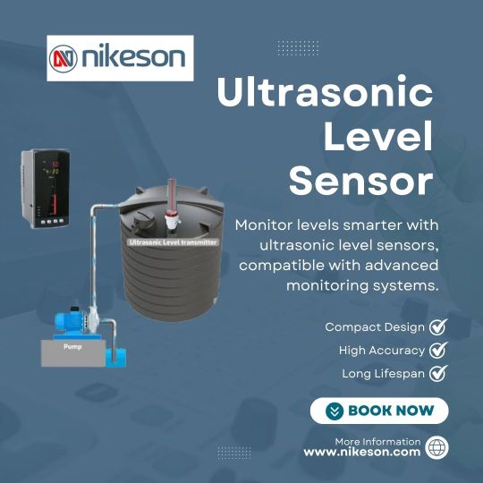
Upgrade industrial operations with the ultrasonic level sensor, offering exceptional precision and durability. Discover how it fits your application needs at Nikeson.
#ultrasonic level sensor#Ultrasonic Level Transmitter#water level gauge#water level staff gauge#water tank level indicator#tank level staff gauge#tank level gauge#water tank gauge#level indicators for water tanks#rainwater level indicator#water level indicators for water tanks#level indicator water tank
0 notes
Text

NASA scientific balloon flights to lift off from Antarctica
NASA's Scientific Balloon Program has returned to Antarctica's icy expanse to kick off the annual Antarctic Long-Duration Balloon Campaign, where two balloon flights will carry a total of nine missions to near space. Launch operations will begin mid-December from the agency's Long Duration Balloon camp located near the U.S. National Science Foundation's McMurdo Station on the Ross Ice Shelf.
"Antarctica is our cornerstone location for long-duration balloon missions, and we always look forward to heading back to 'the ice,'" said Andrew Hamilton, acting chief of NASA's Balloon Program Office at the agency's Wallops Flight Facility in Virginia. "It's a tremendous effort to stage a campaign like this in such a remote location, and we are grateful for the support provided to us by the U.S. National Science Foundation, New Zealand, and the U.S. Air Force."
This year's Antarctic campaign includes investigations in astrophysics, space biology, heliospheric research, and upper atmospheric research, along with technology demonstrations. The campaign's two primary missions include:
GAPS (General Anti-Particle Spectrometer), led by Columbia University in New York, is an experiment to detect anti-matter particles produced by dark matter interactions. The anti-particles stemming from these interactions in our galaxy can only be observed from a suborbital platform or in space, since Earth's atmosphere shields us from the cosmic radiation. GAPS aims to provide an unprecedented level of sensitivity to certain classes of anti-particles, allowing the exploration of a currently unexplored energy regime of the elusive dark matter.
Salter Test Flight Universal, led by NASA's Columbia Scientific Balloon Facility in Palestine, Texas, will test and validate long-duration balloon and subsystems, while supporting several piggyback missions on the flight.
Piggyback missions, or smaller payloads, riding along with the Salter Test Flight Universal mission include:
MARSBOx (Microbes in Atmosphere for Radiation, Survival, and Biological Outcomes Experiments), led by the U.S. Naval Research Laboratory, will expose melanized fungus, called Aspergillus niger, to the stratosphere's extreme radiation and temperature fluctuations, low atmospheric pressure, and absence of water—conditions much like the surface of Mars. Knowledge of how this fungus adapts to protect itself in this harsh environment could lead to the development of treatments to protect astronauts from high radiation exposure.
EMIDSS-6 (Experimental Module for Iterative Design of Satellite Subsystems 6), led by National Polytechnical Institute − Mexico, is a technological platform with experimental design and operational validation of instrumentation that will collect and store data from the stratospheric environment to contribute to the study of climate change.
SPARROW-6 (Sensor Package for Attitude, Rotation, and Relative Observable Winds—6), led by NASA's Balloon Program Office at NASA Wallops, will demonstrate relative wind measurements using an ultrasonic anemometer designed for the balloon float environment.
WALRUSS (Wallops Atmospheric Light Radiation and Ultraviolet Spectrum Sensor), led by the Balloon Program Office at NASA Wallops, is a technology demonstration of a sensor package capable of measuring the total ultraviolet wavelength spectrum and ozone concentration.
INDIGO (INterim Dynamics Instrumentation for Gondolas), led by the Balloon Program Office at NASA Wallops, is a data recorder meant to measure the shock, rotation, and attitude of the gondola during the launch, float, and landing phases of flight. Data will be used to improve understanding of the dynamics of flight and to inform the design of future components and hardware.
The remaining two piggyback missions are led by finalists of NASA's FLOATing DRAGON (Formulate, Lift, Observe, And Testing; Data Recovery And Guided On-board Node) Balloon Challenge, sponsored by the Balloon Program Office at NASA Wallops and managed by the National Institute of Aerospace.
The challenge was created for student teams to design, build, and fly an autonomous aerial vehicle, deployed from a gondola during a high-altitude balloon flight. The teams' student-built data vaults will be safely dropped from around 120,000 feet with the capability to target a specific landing point on the ground to manage risk. The missions participating in the Antarctic campaign are Purdue University's Purdue DRAGONfly, and University of Notre Dame's IRIS v3.
NASA's zero-pressure balloons, used in the Antarctic campaign, are made of a thin plastic film and are capable of lifting up to 8,000 pounds of payload and equipment to altitudes above 99.8% of Earth's atmosphere. Zero-pressure balloons, which typically have a shorter flight duration from the loss of gas during the day-to-night cycle, can support long-duration missions in polar regions during summer.
The constant daylight of Antarctica's austral summer and stable stratospheric wind conditions allow the balloon missions to remain in near space for days to weeks, gathering large amounts of scientific data as they circle the continent.
TOP IMAGE: A scientific balloon is inflated during NASA’s 2023 Antarctic campaign in McMurdo, Antarctica. Credit: NASA/Scott Battaion
LOWER IMAGE: NASA’s Long Duration Balloon camp is located about eight miles from the U.S. National Science Foundation’s McMurdo Station on Antarctica’s Ross Ice Shelf. Credit: NASA/Scott Battaion

4 notes
·
View notes
Text
How to Make Sure Your Well Water is Free of Contaminants
If you're purchasing a home with a well in North Georgia or selling a home with a well, water quality is an absolute priority. Private wells don't have the benefit of municipal water systems, which means they need to be tested regularly and serviced to deliver safe drinking water. Here's what all well owners should know about safeguarding their water supply.

Why Water Testing Is Important
For residential homeowners, routine water testing for quality gives you peace of mind regarding the health of your family. If you have a well and are selling a home, up-to-date water test results make your property more desirable to potential buyers. If you're purchasing a home with a well, thorough water testing should never be an option due to your inspection time.
While North Georgia well level testing to determine water amount is a priority for many, quality testing is just as essential. An established well water level measuring company can frequently offer water quality testing as an added service, providing you with a whole picture of your water supply.
Common Contaminants in North Georgia Wells
Our area has particular water quality issues such as naturally occurring minerals such as iron and manganese, farm runoff with nitrates, septic system bacteria, and industrial contaminants in certain areas.
Professional Testing vs. DIY Kits
Although home test kits exist, using a professional company that tests well water levels and quality has a number of benefits. More precise results, testing for more contaminants, correct sampling procedures, and expert interpretation of results make professional testing worth the cost.
North Georgia well level testing and water quality analysis by professionals involve the use of specialized equipment and strict protocols to provide reliable results.
Testing Frequency Recommendations
Annual bacterial and nitrate testing is needed, and a full mineral analysis every 3-5 years. Extra testing must be done after significant flooding or construction near the well, and always prior to purchasing or selling a home with a well.
Protecting Your Well from Contamination
In addition to testing, owners of wells should have good wellhead protection and keep harmful chemicals out of the well area. Periodic inspection of the well casing and cap, as well as surveillance of land use changes in the surrounding area, prevents contamination problems.
For Buyers and Sellers
If you're purchasing a home with a well, check all available water quality records and ask for new testing if records are old. Test for local-specific contaminants, too. When selling a home with a well, have recent water test results on hand, fix any known water quality problems, and be ready to describe your maintenance schedule to potential buyers.
Take Action Today
Don't wait until you have a problem to have your water tested. Call a professional North Georgia well level testing and water quality company to arrange thorough testing. Whether you're purchasing, selling, or just keeping a home with a well, clean water is worth its weight in gold.
#well depth gauge#portable ultrasonic level sensor#well water level sensor#what is the deep well water level sensor?#buying a home with a well#selling a home with a well
0 notes
Text
Ultrasonic Sensors: A Comprehensive Guide
Ultrasonic sensors are devices that use ultrasonic waves, which are sound waves with frequencies higher than the audible range for humans (typically above 20,000 hertz), for various applications.
These sensors operate on the principle of sending out ultrasonic waves and measuring the time it takes for the waves to bounce back after hitting an object. This information can then be used to determine the distance or presence of the object.
Ultrasonic Sensors Working Principle
The working principle of ultrasonic sensors is based on the transmission and reception of ultrasonic waves. Here’s a step-by-step explanation of how these sensors operate:
Generation of Ultrasonic Waves:
Ultrasonic sensors consist of a transducer, typically a piezoelectric crystal, that can convert electrical energy into ultrasonic waves. When an electrical voltage is applied to the crystal, it vibrates and generates ultrasonic waves in the frequency range beyond human hearing (typically above 20,000 hertz).
Wave Emission:
The ultrasonic sensor emits a short burst of ultrasonic waves into the surrounding environment. This burst of waves travels outward from the sensor.
Wave Propagation:
The ultrasonic waves move through the air until they encounter an object in their path. The waves continue to propagate until they hit a surface.
Reflection of Ultrasonic Waves:
When the ultrasonic waves strike an object, they are reflected back towards the sensor. The reflection occurs because the ultrasonic waves encounter a change in the medium (from air to the object’s surface), causing the waves to bounce back.
Reception of Reflected Waves:
The same transducer that emitted the ultrasonic waves now acts as a receiver. It detects the reflected waves returning from the object.
Time Measurement:
The sensor measures the time it takes for the ultrasonic waves to travel from the sensor to the object and back. This time measurement is crucial for determining the distance to the object.
Distance Calculation:
Using the known speed of sound in the air, which is approximately 343 meters per second (at room temperature), the sensor calculates the distance to the object. The formula for distance (D) is given by D = (Speed of Sound × Time) / 2.
Output Signal:
The calculated distance information is then processed by the sensor’s electronics, and the output is provided in a suitable format, often as an analog voltage, digital signal, or distance reading.
These sensors work by emitting ultrasonic waves, detecting their reflections from objects, measuring the time taken for the round trip, and using this time information to calculate the distance to the objects in their detection range. This working principle is fundamental to various applications, including distance measurement, object detection, and obstacle avoidance.
Ultrasonic Sensors Pins Configurations
The pin configurations of ultrasonic sensors may vary depending on the specific model and manufacturer. However, We will discuss general overview of the typical pin configuration for a commonly used ultrasonic sensor module, like the HC-SR04. This module is widely used in hobbyist and educational projects.
The HC-SR04 ultrasonic sensor typically has four pins:
VCC (Voltage Supply):
This pin is used to provide power to the sensor. It typically requires a voltage in the range of 5V.
Trig (Trigger):
The Trig pin is used to trigger the start of the ultrasonic pulse. When a pulse of at least 10 microseconds is applied to this pin, the sensor emits an ultrasonic wave.
Echo:
The Echo pin is used to receive the ultrasonic waves that are reflected back from an object. The duration of the pulse received on this pin is proportional to the time it takes for the ultrasonic waves to travel to the object and back.
GND (Ground):
This pin is connected to the ground (0V) of the power supply.
Read More: Ultrasonic Sensors
#ultrasonic sensors#ultrasonic technology#sensor technology#sensor applications#non-contact measurement#distance measurement#level measurement#flow measurement#object detection#obstacle avoidance#industrial automation#automotive industry#robotics#healthcare#home automation#smart homes#IoT#internet of things#technology#innovation#engineering#science#research#development#education#learning#acoustics#sound waves#frequency#amplitude
0 notes