#Wire Encoder and Sensor
Explore tagged Tumblr posts
Visit Tumblr Blog
Explore Tumblr blogs with no restrictions, modern design and the best experience.
Last Seen Tumblr Blogs


Fun Fact
Celebrities use Tumblr as well.
Text
Explosionproof Displacement Draw Wire Encoder and Sensor with SSI Communication - Briterencoder
0 notes
Text


Quester (1981) by David Buckley, London, UK. Quester was originally designed as a micromouse maze solver, taking part in the Wembley heats of the July 1981 Amazing Micromouse Contest, and in the September 1981 EUROMICRO competition in Paris. It was later converted into a general purpose robot with the addition of a gripper. It uses vision to detect the walls of the maze, and segmented bump sensors in case it doesn't, and uses a layered behaviour control program running on a 6502 based Acorn System 1. Quester was also a finalist in the Robotics Age "Home Robot Photo Contest" (1982), and ultimately won the Thezeus Award 1996 created and presented by Alan Dibley.
"The chassis consists of two main drive wheels with fore and aft casters. The drive wheels are hardboard disks with vacuum-cleaner belts for tires, each powered by a 6V DC motor. Via homemade shaft encoders the motors also drive two 8-bit up/down counters so that a preprogrammed path may be followed. Wire loops connected to micro-switches can be seen around the base - these provide reflexes through hardware timers on the interface board. Power comes from a 6V lead-acid battery in the central column which allows about three hours of service between charges. Twelve photo-transistors arranged as three pairs per side provide obstacle detection. One of each pair senses ambient light while the other is only sensitive to light from a particular direction. … At the front of the chassis are a pair of ultrasonic transducers for range-finding." – Quester, by David L. Buckley, Robotics Age, Jan/Feb 1982.
35 notes
·
View notes
Text


This is my review of the X3 from Attack Shark. I came across this mouse shopping on Amazon by searching "3395 Gaming Mouse". I took a chance and I paid it for $39.17 and received it the same day.
Specs
Sensor: PAW3395
Size: 118.5*61*39.7 mm
Weight: 49±3grams (my copy weighted in at 54g on my scale)
Polling Rate: 125Hz-1000Hz.
Main Click Switches: Kailh Black Mamba Micro-Motion Switches, 80 Million Click
Scroll Wheel: TTC ENCODER
Connectivity: 2.4Ghz Wireless/Bluetooth/USB-C Wired
Battery Life According to the item description: Up to 200Hrs
Build Quality: My first impression of the X3 was, for a peripheral that cost less than a sushi dinner for one, this thing is built fairly well. If I squeeze the heck out of it, there is no creaking or popping. When I shake it, there is a very slight rattle of the scroll wheel, but nothing that you would feel in game (there is no rattle at all on my lavender copy). The bottom of the mouse doesn't flex when I push on it. The clicks feel nice and snappy. They are a little heavier than I would like, but that is my personal preference. There really isn't much pre/post travel on M1 or M2. I enjoy the scroll wheel quite a bit, it has some really nice defined steps and isn't too loud or scratchy. Mouse 3 and 4 feel nice with some post travel. The weight balance seems to be okay, If anything I would say it is potentially a bit back heavy. That may be due to battery placement inside the shell.
Performance: I had no issues with sensor tracking and did not experience any spin out. The polling rate seemed to be stable, and I did not feel any stutter or jitteriness. My main shooters are CS2 and Overwatch 2. I felt I performed well, and the shape really grew on me. The shape seems to pretty much be the Ajazz Aj199 and doing a little searching around Amazon, Attack Shark might even be a sub-brand of Ajazz(?) I don't know that exactly, I could be wrong. I also used the mouse to play Dota 2 and the X3 will now be my main mouse for that particular game moving forward. I use a relaxed claw style grip and have baby hands (17cm x 10cm). I never dealt with cramping or discomfort. Battery life is pretty dang good! It holds are charge for about 10-12 days with about 5-6 hours of use a day. Overall, I had no real issues with the mouse in game. The software is pretty basic, but important to download so you can update the firmware. This will allow you to change the debounce timing.
Overall Thoughts: My overall thoughts about the X3 are that it is a pretty decent little mouse if you are low on funds. Is it anything that shakes up the market or adds something we haven't already seen? Not at all. Is it worth $40? I would say it 100% is. It will be in my rotation moving forward, and I am hoping its durability stands up with the test of time.
Edit: I now have two copies of this mouse and the first one (in white) is still going strong. My Lavender one feels even better build wise. Huge Fan of the Attack Shark X3
#esports#gaming mouse#pc gaming setup#pc gaming accessories#gaming pc#gaming setup#cs2#gaming mouse pad#gamer dad#attack shark#review#techreview
2 notes
·
View notes
Text
Gonna just chime in and add - a lot of traits that are associated with Autism and ADHD are actually 'normal'. The difference here between it just being part of the human experience and actually Autism/ADHD is frequency and/or sensitivity, or even the severity.
For example, in the case of Autism - anyone can experience sensory overload/overwhelm. The mechanism is the same and just goes with 'you have a brain'. You've gotta remember brains are actually sitting in a dark room, all the time interpreting data from the sensors wired into your body (eyes, ears, sense of touch etc.). You bombard those sensors with enough information, they will get overloaded. If you think I'm talking shit as a neurotypical - think shopping centers/malls during Christmas shopping period. Heaps of people, voices echoing off tiles, Christmas music constantly blaring from every corner playing a different song out every door, kids screaming and crying, smells of food and perfume mixing together (idk they always have pop up stalls here in Australia right in the thoroughfares) people jostling your elbows, if you're where I am add 'probably sweaty af because of the heat outside before you came in'.
Anyone would feel absolutely wiped having to deal with that for a few hours straight. That is sensory overload.
The difference between a neurotypical (normal neurology) and someone with Autism is our sensitivity is jacked up way too high. There's various theories as to why, I think the current? front-runner is it's reduced synaptic pruning - basically meaning Autistic's possibly retain more synaptic connections from infancy than others. To put it into an analogy, imagine you have a 'volume' knob for your senses. Yours is sitting (as a neurotypical) at a nice level that you can manage in daily life. The Autistic person however, has it turned up to maximum volume - double your own experience. Suddenly it becomes clear how something that would normally be overwhelming for one person can trigger a complete meltdown in their neurological system resulting in either a meltdown, shutdown or total disassociation from the body in the brain's attempt to mitigate harm. Also given Autism is considered a spectrum, everyone's volume knobs are set a bit different. Some might be really strong for some things, but not others and that'll vary from person to person.
Now for an ADHD example - yes, we all forget things. Everyone has probably experienced the phenomenon known as the 'Doorway Effect' whereby entering a room to go get something - you've suddenly forgot why you're there. And then have to go retrace your steps back to the previous room to 'remember' it, as if you left your brain behind when you changed rooms.
The theory around this is due how to the brain encodes memory, and this might mean a few things get chucked out by accident when you change rooms because your brain is, unawares to you, having to change gear the moment you cross that threshold as it 'processes' the different room. Your brain is relating the memory of what you needed to get before in time and space so it can tell what has passed, what is present etc. (if your brain didn't do this, you'd have a detached sense of time which is a major component of Schizophrenia) This also explains why going BACK to the room can bring back the memory. Your brain just dropped it on the way out.
But for someone with ADHD, if you're doing this so often to the point you feel like you lack object permanence or you feel like unless you can see it constantly, your brain will probably forget it exists? That's ADHD. An ADHD brain has problems with binding dopamine receptors which help us stay motivated and attentive. It's a bit like your short term memory is like a table in front of you where you line up all the things you're supposed to currently be 'remembering' but the ADHD component is the cat that's constantly prowling the table and smacking off things that don't generate enough dopamine. So the memories often end up on the floor and now it's been the fourth week in a row you forgot to put the bin out (me, btw 💀).
This of course, can happen to 'normal' people too - we are running virtually the same hardware. But the differences I am describing here are what we consider disordered.
This is what I think a lot of people forget when accusations of self-diagnosis/statements like 'everyone's a bit x' are thrown around. We're forgetting it's in the name, Autism Specrtum Disorder, Attention Deficit/Hyperactivity Disorder. The defining characteristic of all of these 'symptoms' that get talked about, is they are at a disordered level that is interrupting day to day life and/or making it unable for someone to function as well in our societal structure (this is your hint to go look up the Social Model of disability btw).
So yes, everyone forgets things. Everyone can feel overwhelmed by music that's too loud etc. The difference is this - take whatever that thing is that annoys you, now double it. Now it's a problem. It's disordered.
So yeah, next time someone tries to tell you you're maybe making shit up or you're seeing a lot of people on what I'd arguably call the Autism webbed site (there is a BIG correlation between neurodivergence and fandom btw) going 'oh me too?' maybe it's not a good sample size and if you've got the feeling something about you is off - do your research (from reputable sources, and no an Autistic person cannot be a perfect source because it affects everyone differently) and talk to your doctor.
Also P.S. self-diagnosis if you consider yourself adequately informed and find it useful and/or supported by a medical practitioner like your doctor or psychologist but cannot legally diagnose you - IS. VALID.
Costs - especially for adults - to get diagnosis are often prohibitive, and considering most studies confirm if you're Autistic you're more likely to be unemployed in the first place it's a massive catch 22. My diagnosis' cost me about 4-5k AUD in total. I did not pay for it, my parents did - and I know not everyone will get access to that.
So be kind people. And talk to your doc pls.
(P.S.S. No this isn't to rail on OP or anything this is just a thing I've been thinking about and think needs clearing up for a lot of peeps. We're forgetting what 'disorder' is. Talk to a health professional if you can. Do your research too.)
Edit: I realised I goofed and repeated myself, that's fixed also changed the link for the synaptic pruning to a better one. Shit happens when it's due more ADHD meds o'clock lol.
Pro tip if you see at least 50 people say "wait that's not normal??" In the comments of some neurodivergent relatability post then it probably is, in fact, normal. Daydreaming to songs is normal, I promise you. Most everything about being neurodivergent is normal, it's just the degree to which it affects you and your life that makes it abnormal.
#audhd things#neurodiversity#kerytalk#this goddamn tag againnnnnnnnn#I have too much down time ok and I spend all of it reading books and studying neuroscience (currently)#these analogies came to me after combining an amalgam of things I've learned over the years since a friend was considering diagnosis#my opinion on diagnosis btw: if cost is prohibitive - self diagnosis is valid#if you can manage without a diagnosis anyway and the knowledge and coping strategies are enough for you - self diagnosis is also valid#however IF you think a physical on paper diagnosis would ease your mind and/or help you access support you need - get it if you can#when self-diagnosis is not valid = you are literally doing it for fucking attention and you're an asshole#I will swap my neurology with yours come and enjoy my chronic fatigue and being unable to do shit#also I'll fight you in a parking lot#my commentary
41K notes
·
View notes
Text
What You Will Learn in Industrial Automation and Robotics Courses?
Traditional manual processes have now transformed into smart systems that respond with speed and precision. From packaging lines that operate around the clock to robotic arms performing delicate tasks with surgical accuracy, the world of industrial production is evolving. And at the heart of this change lies a new kind of technical literacy, one built through Industrial automation and robotics courses.
But what exactly do these programs teach? And why are they so important today? Let’s explore what students really gain from this kind of education, and how it prepares them to thrive in tomorrow’s industries.
Foundational Engineering Knowledge That Matters
Before students can dive into robots or controllers, they need to understand the language of automation. These courses begin with essential principles: electrical theory, logic design, mechanical fundamentals, and system dynamics. Learners study current flow, sensors, basic circuits, and safety devices. They also explore control systems, how feedback works, what makes a loop stable, and how machines respond to various inputs.
Programmable Logic Controllers (PLCs)
Programmable Logic Controllers, or PLCs, form the core of most industrial automation systems. Unlike traditional relay setups, these compact computers carry out control tasks instantly by following logic sequences built by engineers. Students gain direct experience working with real hardware, learning to configure, test, and program PLCs using industry-standard languages such as ladder logic, structured text, and function block diagrams.
Courses focus not just on writing code but on solving problems: detecting errors, optimizing sequence flow, and debugging physical setups. Whether it’s running a simulated traffic light or managing conveyor timing, the logic must be precise.
Human-Machine Interfaces (HMI) and SCADA Systems
As machines grow smarter, the need for clear communication between systems and humans increases. That’s where HMI and SCADA systems come in.
Students learn to design interactive screens that allow operators to control and monitor processes, from pressure levels in a reactor to the speed of a bottling line. They develop layouts, manage alarms, create trend graphs, and set up data logging.
Equally critical is understanding SCADA architecture, how large-scale systems monitor multiple devices across facilities. These interfaces aren’t just dashboards. They’re lifelines. In high-risk or high-speed environments, the right display can prevent failure.
Robotics: Control, Precision, and Integration
Beyond sensors and switches, industrial robotics introduces a whole new dimension. These machines perform physical tasks with accuracy and consistency, from welding to material handling. In Industrial automation and robotics courses, students explore robotic motion planning, coordinate systems, joint movement, and gripper design.
Training includes simulation as well as real robotic arms. Learners program actions, define tool paths, and calibrate devices to respond to various scenarios. Robotics also demands a sharp eye for safety, understanding fail-safes, emergency stops, and risk analysis becomes part of the curriculum.
Sensor Technology and Instrumentation
In automation, sensing is everything. Machines need to detect position, measure flow, monitor temperature, or determine proximity, all without human input. That’s why students spend time studying sensors in depth.
They learn the theory and application of photoelectric sensors, limit switches, ultrasonic devices, thermocouples, and encoders. Courses often include wiring, calibration, signal processing, and sensor fusion techniques.
It’s one thing to install a sensor. It’s another to ensure its readings are accurate, consistent, and usable within an automation loop. A well-tuned sensing system is the difference between reliable automation and constant failure.
Drives, Motors, and Motion Control
Movement in automation is never random. Whether it’s a robotic arm pivoting or a conveyor transporting items, motion must be controlled, smooth, and predictable.
Students study various types of motors, stepper, servo, induction, and the drives that control them. They learn to manage speed, torque, and direction. Courses also explain PID control, acceleration curves, and how to prevent vibration or misalignment.
Practical lab work allows learners to connect motors, set drive parameters, and test results under different loads. These experiences create engineers who don’t just understand motion, they can manage it with precision.
Integration Projects: From Concept to Commissioning
Toward the end of most programs, students apply everything they’ve learned in a capstone project. This may involve designing an automated process from scratch, selecting hardware, building control logic, integrating sensors, and testing systems.
It’s not just a test. It’s preparation. It simulates real challenges, including incomplete specs, equipment failure, or changing project goals. The experience builds not only confidence but also the kind of problem-solving mindset employers look for.
Safety, Compliance, and Standards
No system, no matter how efficient, is worth endangering a worker’s life. That’s why safety is woven throughout every topic. They learn how to design systems that prevent unexpected starts, reduce hazards, and shut down when needed.
They also learn to assess risk, calculate safety integrity levels, and implement proper machine guarding. These aren’t theoretical concerns, they’re daily priorities in every automation role.
Final Thoughts
For anyone looking to step into a future-proof career, technical depth and adaptability are essential. Industrial automation and robotics courses offer both. They build an understanding of how machines function, how systems connect, and how processes can be improved through smart engineering. Whether you aim to be a systems integrator, controls engineer, maintenance lead, or robotics programmer, what you learn in these courses is more than skill, it’s your launchpad into a smarter, faster world.
0 notes
Text
Automated Production and Testing Processes of Rocker Switches

1. Introduction
With the rapid development of industrial automation, the manufacturing process of rocker switches has undergone a transformation from traditional manual production to highly automated, precision-controlled production lines. This shift not only improves production efficiency and product consistency but also enhances the competitiveness of enterprises in the market. This article will provide a comprehensive overview of the automated production and testing processes of rocker switches, including automated terminal insertion, automated spot welding, automated LED placement, as well as contact resistance testing, travel and pressure testing, continuity time measurement, and industrial vision-based appearance inspection. These technologies represent a high degree of integration between mechanical systems, electronic control, and intelligent algorithms.
2. Automated Assembly Processes in Rocker Switch Production
2.1 Automated Terminal Insertion
Terminal insertion is one of the most critical steps in rocker switch production. Traditional manual insertion is prone to positional deviation and insertion force instability, which may cause defective contact or product rejection. Modern production lines adopt servo-controlled automated terminal insertion systems, which use multi-axis manipulators to position terminals precisely. High-precision optical sensors ensure insertion depth and orientation consistency.
For instance, the system automatically picks the copper terminal from the feeder, precisely aligns it with the switch base, and inserts it at a controlled speed and pressure. This ensures the mechanical integrity of the assembly and avoids micro-damage to the plastic shell, laying a solid foundation for subsequent spot welding.
2.2 Automated Spot Welding
Spot welding ensures the electrical connection between terminals and leads. The automated welding station uses resistance spot welding controlled by pulse current and time curves to precisely fuse metal interfaces.
Advanced systems are equipped with closed-loop current monitoring and displacement sensors, allowing real-time compensation for contact surface changes, thus ensuring stable and low-resistance welded joints. Additionally, the system is integrated with fume extraction and safety monitoring modules, improving the working environment and overall safety.
2.3 Automated LED Placement
Rocker switches with indicator lights require precise LED placement. Automated LED placement machines use high-speed pick-and-place heads and machine vision calibration to accurately position the LED within the switch cavity. The polarity and brightness are verified in real time during the process to ensure optical performance and visual consistency.
This process ensures that the LED does not shift during encapsulation or welding, maintaining long-term reliability and aesthetic appeal of the final product.
3. Automated Testing Systems for Rocker Switches
To ensure product reliability, each rocker switch must undergo comprehensive electrical and mechanical performance tests before leaving the factory.
3.1 Contact Resistance Test
The contact resistance test evaluates the resistance value across the conductive path under rated pressure. Modern automated testing equipment uses a 4-wire Kelvin method to eliminate lead resistance influence. The system can test multiple switches simultaneously, display resistance distribution curves in real-time, and automatically classify unqualified products.
Typical requirement: contact resistance < 50 mΩ (depending on the application scenario).
3.2 Travel and Pressure Test
Travel and pressure tests ensure the rocker switch provides the correct tactile feedback. High-precision linear actuators simulate human finger pressing motion, while pressure sensors and displacement encoders collect force-displacement data.
This allows evaluation of stroke range (e.g., 1.8–2.5 mm), actuation force (e.g., 300–600 gf), and pressing smoothness. Abnormalities such as mechanical jamming, misalignment, or inconsistent feedback can be identified and rejected automatically.
3.3 Continuity Time Measurement
Continuity time refers to the response speed of the switch after actuation. The test system uses high-speed data acquisition cards to detect signal transition points and calculate the time difference between actuation and circuit conduction.
This indicator is especially important for automotive and industrial control applications, where millisecond-level response times are required.
4. Visual Inspection and Intelligent Defect Detection
4.1 Industrial Vision System Introduction
Visual inspection replaces traditional manual quality checks, using high-resolution cameras, lighting modules, and image recognition algorithms to inspect every rocker switch.
It can detect:
Missing parts
Scratches or deformation on the housing
Logo misalignment or blurring
Incorrect assembly (e.g., misaligned rockers, LED offset)
4.2 High Efficiency and Accuracy
For example, a dual-camera system combined with a rotary conveyor can inspect 120 pieces per minute. The system achieves a detection accuracy of 0.05 mm, capable of identifying minute cracks or flash edges on plastic parts.
Deep learning algorithms further enhance recognition ability by learning from real production defects, continuously optimizing detection logic.
5. Traceability and Data Integration
All testing data and inspection results are integrated into the MES (Manufacturing Execution System), enabling full traceability. This helps:
Identify root causes of quality issues quickly
Analyze yield trends
Refine production parameters in real time
By applying barcode/QR code identification to each unit, data from insertion, welding, testing, and inspection can be correlated with the specific product batch, greatly enhancing quality control and accountability.
6. Conclusion
The automated production and testing processes of rocker switches represent the future trend of smart manufacturing in the electromechanical components industry. From terminal insertion to visual inspection, each step is carefully controlled and monitored, improving production efficiency, product quality, and cost-effectiveness. With continued development in industrial AI and robotics, the production of rocker switches will become even more intelligent, flexible, and scalable, helping enterprises meet the diverse and demanding needs of global markets.
en.dghongju.com
0 notes
Text
In its broadest sense, remote control systems also include those systems that rely on the use of extended physical control links (i.e., using a physical link such as cables or wires and other similar conductors). More typically, however, the phrase is used to refer to wireless connections. There are four important kinds of remote control systems in common use: radio control, infrared remote control, remote-handling equipment, and telemetry (Cavendish, 2006). Radio control technology Radio control is the most common type of remote control, and at times the two terms are used interchangeably. As the term implies, this is a way of directing the operation of one or several devices from some distance away, through the use of radio waves. There are single-channel and multichannel control equipment. Single channel equipment are designed to control only one function, while multichannel equipment can control several functions (Cavendish, 2006). The single-channel radio control is comprised of a transmitter, a relay, and an actuator or escapement. The transmitter is the device that sends a constant-frequency radio signal when its keying switch is moved. The signal is detected by the receiver and then amplified, triggering the relay which activates the actuator. It is the actuator that executes the single function command which the operator desires to be done. Because the single channel control can only operate one function, it is rather limited and operates basically by switching the function on and off (Cavendish, 2006). The multichannel radio control system, on the other hand, is designed to handle more than one function. Early models used tone transmitters that produced up to 12 ultrasonic tones; today, however, multichannel RC systems use digital pulsing systems which are more reliable and precise and therefore provide for finer control than tone transmitters. When the transmitter is switched on, it produces a series of pulses continuously. The message is encoded in the spaces between pulses; the signal containing the pulses is received and amplified by the receiver, after which it is passed on to a decoder (Cavendish, 2006). Infrared remote control On the other hand, infrared remote control is probably the most familiar because it is widely used in a home setting, for operating electrical entertainment systems and similar devices. Infrared RC uses pulses of invisible infrared light as the medium of control; unlike radio control, it is important that infrared transmitters have a line-of-sight path to the sensor on the device being controlled. One characteristic of infrared is that it may bounce off walls, but not penetrate them (Cavendish, 2006). Upon depressing a button on an infrared remote-control handset, a microchip in it activates a signal to which the button relates. The signal is amplified by transistors and sent to a light-emitting diode (LED) that translates the signal to infrared light. The LED is located at the handset’s front, so the light that is generated is sent to the device where a sensor detects it and prompts the desired action (Cavendish, 2006). Read the full article
0 notes
Text
Winter break progress
Pivoting my focus of Senior Capstone project to playability and bringing awareness to games that never left japan and recreating their unconventional control schemes by using leftover materials and reusing/recycling old parts to perfectly emulate the arcade experience. This project is to help raise awareness for these games and let people outside of japan be able to play and fully experience these types of new & interesting interactive media that stayed exclusive to Japan for so long. For this project I am focusing on recreating 2 japan exclusive games in particular:
Hyper Bishi Bashi Champ
and Gaia Attack 4


I chose these two games for a couple of reasons:
They allow for a large number of people to play at once so it is more fun & engaging in a group setting (3 players for Bishi Bashi and 4 players for Gaia Attack)
These games both have unconventional and interesting control schemes that are intuitive and very user friendly while also being difficult to replicate outside of the arcade (gaia attack is a 4 player light gun game - might in fact have been the very first one to ever exist in an arcade setting. Ghost squad on wii had a four player mode but Gaia attack 4 might have been one of if not THE first 4 player light gun game in arcades. As for bishi bashi it is a minigame compilation that plays very similar to wario ware HOWEVER it actually predates wario ware by about 6 or 7 years. It uses a 3 button layout, red, blue, and green to play several different minigames)
Both of these games have an english translated version of them however it was only used for localization testing and unfortunately never made it to the west (Hyper bishi bashi might have been sold in select parts of Europe but Gaia attack 4 definitely only stayed in japan outside of exports) - but thanks to recent advancements in arcade emulation both of these games are able to be played on PC which is how I'll be attempting to recreate their setups that they had in the arcade
Both of these games also have very interesting light outputs that thanks to a certain program called mamehooker we can actually pick up those light outputs and use them to replicate what the arcade button lights would have looked like by using another device called a PacDrive that can turn led buttons on and off dynamically (Left - Box with Keyboard encoder and PacDrive - encoder will translate button presses to keyboard keys which can then be binded in the emulator while the PacDrive deals with each indivdual buttons own led outputs, Right - Mamehooker code ran in the background while game is playing which is then used to tell the PacDrive when to turn each button on and off during gameplay)


Currently for the Gaia Attack 4 cabinet I have since completed modding all 4 old broken lightguns I bought off ebay to be converted in PC lightguns as well as soldering and connecting all 4 sensors needed to use the Gun4IR program that makes the guns work for computers. This way I can play the game via an emulator on a special mini PC I bought that supports a large amount of usb hubs capable of having all 4 guns operational at once, thus fully recreating the 4 player arcade experience


I'm going to focusing on creating additional things like the marquee and the start buttons after I finish getting the Bishi Bashi cabinet working. I ordered a bunch of 12V arcade buttons who's colors match what is seen on an original bishi bashi arcade cabinet and tried soldering the pacdrive and keyboard encoder wires to it to get it to work. I've since started tinkering with the pacdrive and keyboard encoder and have managed to get one of the buttons to hook up in sync with the game as can be seen in this video - https://youtu.be/vgcoYbzzwVM?si=tfQEttBDrflTiNCW

While this is good substantial progress, I tried hooking up two buttons later and couldnt get it to work unfortunately so there is still is a lot of troubleshooting and tweaking I will most likely have to do and go back and resolder to wires or check the connections with a multimeter to see where I went wrong. I will continue to post future updates as I make progress on my capstone project.
1 note
·
View note
Text
Top 10 CNC Machine Failures & Troubleshooting Tips

CNC machines are essential in modern manufacturing, but they can experience various failures. Recognizing these issues early can save time and prevent costly repairs. Here are the top 10 common CNC machine failures and how to fix them:
CNC Spindle Problems: Overheating, vibration, or noise can occur due to bearing failure or misalignment. Fix: Regular lubrication, alignment, and bearing checks.
Tool Breakage: Caused by worn-out tools, incorrect feed rates, or poor tool selection. Fix: Use sharp, appropriate tools and adjust feed rates.
Overheating: Leads to downtime and accuracy loss. Fix: Ensure proper coolant flow and clean ventilation systems.
Programming Errors: Incorrect G-codes or parameters can cause crashes. Fix: Double-check G-code, use simulations, and train operators.
Vibration: Can ruin surface finish and reduce tool life. Fix: Balance tools, check spindle alignment, and tighten loose components.
Poor Surface Finish: Dull tools or incorrect cutting speeds are common culprits. Fix: Replace dull tools and optimize speeds.
Axis Positioning Issues: Caused by faulty encoders or worn ball screws. Fix: Calibrate regularly and replace faulty parts.
Electrical Failures: Power surges, faulty wiring, and blown fuses disrupt operations. Fix: Inspect wiring, use surge protectors, and replace fuses.
Overloading: Can damage motors and tools. Fix: Follow machine specs, avoid overuse, and monitor loads.
Sensor Malfunctions: Inaccurate readings lead to errors. Fix: Regularly check and replace faulty sensors.
Key Takeaway: Regular maintenance and proactive troubleshooting are key to keeping CNC machines running smoothly. Get Read Full Article:- https://squickmons.com/top-10-cnc-machine-failures-troubleshooting-solutions/
0 notes
Text

Explosionproof Displacement Draw Wire Encoder and Sensor with SSI Communication
Key features
Exceptional Durability: Designed for 5 million fatigue cycles, ensuring long-lasting performance.
Advanced Digital Communication: Absolute position sensing with power-off memory for reliable data retention.
Durable Wire Outlet: Ceramic material enhances wear resistance, extending the life of the steel wire rope.
Data Interfaces: Equipped with Explosionproof SSI connections to facilitate seamless data integration and communication.
High-Quality Construction: Features a 0.8mm diameter, imported flexible stainless steel wire rope with a nylon coating for reduced friction and enhanced durability.
Superior Pull Head Design: Special fixation method with a tensile limit 10 times greater than competitors, allowing for a 15° angle deviation.
Visit https://briterencoder.com/product/explosionproof-displacement-draw-wire-encoder-and-sensor-with-ssi-communication/ for more.
0 notes
Text


MITEE 7 (1994) by David Otten and Tony Caloggero, MIT. MITEE Mouse 7 won the 15th All Japan Micromouse Competition in 1994, with a time of 11.81 seconds. It's a four wheeled mouse with DC motors. MITEE 7 also took part in Techno Games in 2002. "In its Heat it fought against returnee Dash 2A. Mitee Mouse 7 raced through the maze at incredible smooth speeds. It slipped through corners and even avoided twisting and turn, opting to go diagonally ahead. The robot sped through to the centre at a World Record time of 9:65 seconds." – Techno Games Wiki.
"MITEE 7 is another of Dave Otten's successful micromouse designs in collaboration with Tony Caloggero. This is a four wheel drive, four wheel steering mouse. While mechanically, and computationally, more complex than two wheel machines, there are a couple of significant advantages to a four wheel mouse. Chief of these is in going quickly. As you accelerate a mouse, weight is naturally transferred to the rear of the vehicle. If you only have two driving wheels as in a typical wheelchair design, this will mean reduced downforce on those wheels and a reduction in the possible acceleration you can achieve. With four wheels working together, they all get to do some work whatever the weight distribution. Each motor need only have ½ the torque needed in a two-wheel mouse and can be correspondingly smaller. There are eight DC motors to look after in this mouse - one each todrive the four wheels and one each to steer them. Sensing is with the same PSD based side-looking sensors that have been used in other MITEE mice. Encoders and gear quadrants form part of a digital servo loop for steering. The green and yellow wires passing down through the gears provide power to the drive motors." – Pete Harrison.
The first video is an excerpt from "UK Micromouse 1998" showing MITEE 7 on a training run, while the second snippet is a full-speed race to the centre (from the same source).
#cybernetics#robot#micromouse#All Japan Micromouse Competition#15th All Japan Micromouse Competition#UK Micromouse 1998#MITEE#maze solvers
15 notes
·
View notes
Text
AdLink I-Pi SMARC 1200 Plus DevKit With MediaTek Genio 1200
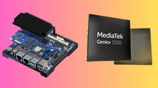
I-Pi SMARC 1200
AdLink I-Pi SMARC 1200 Plus DevKit, an octa-core MediaTek Genio 1200 processor-powered AI and graphics-focused solution. The octa-core Arm Cortex-A78 and Cortex-A55 CPUs in the Genio 1200 are paired with a 5-core Arm Mali-G57 GPU for cutting-edge 3D graphics and an embedded NPU that can handle up to 5 TOPS of edge AI data.
The on-device AI processing capabilities of the I-Pi SMARC 1200 include computer vision and deep learning neural network acceleration. Moreover, up to three MIPI camera inputs and several 4K displays are supported by the SMARC. For a variety of next-generation AI focused developments, including smart homes, industrial IoT, 3K multimedia apps, and human-machine interfaces, this is the go-to option. Product developers can explore new avenues and expedite proof of concept creation before production with the dev kit, which lowers costs and shortens time to market.
Pi SMARC 1200
MediaTek Genio 1200 platform
The Octa-core MediaTek MT8395 powering the LEC-MTK-I1200 module (Cortex-A78 x4 + A55 x4 in the arm)
The Smart Mobility Architecture, or SMARC Form Factor
SMARC 2.1 specification: a very small and power-efficient design appropriate for edge computing and embedded applications.
Due to its small size (82 x 80 mm), it is perfect for designs that need to save space, like industrial IoT systems, robotics, smart home appliances, and AI cameras.
All-encompassing Connectivity
Support for Bluetooth 5.2 and Wi-Fi 6 allows for fast wireless data transfer.
Support for optional 5G: Enables cellular high-speed connectivity for Internet of Things applications that need dependable network access.
Gigabit Ethernet: Quick connectivity for edge devices via wired networks.
Display and Graphics
Equipped with a Mali-G57 GPU, capable of encoding and decoding 4K60 HDR video.
There are several display interfaces available for connecting high-definition monitors and displays, including as HDMI, eDP, and MIPI DSI.
A Variety of I/O Interfaces
Peripheral connectivity via PCIe, USB 3.1, and I2C enables expansion with extra parts including cameras, sensors, and storage devices.
AI cameras can be connected via the MIPI CSI camera interface, which is helpful for robotics and smart surveillance applications.
AI & Machine Learning on the Edge
For real-time decision-making, the AI Processing Unit reduces dependency on cloud computing by enabling effective AI inferencing at the edge.
Perfect for jobs involving natural language processing, computer vision, and machine learning.
Stored Information and Memory
Supports high-speed memory operations with LPDDR4x RAM.
Sffers external SD card ports, UFS, and eMMC as storage options.
Low Power Need
It is appropriate for battery-powered IoT devices such as smart cameras, portable robotics, and IoT sensors because it was designed with energy efficiency in mind.
Uses in Industry
Suitable for industries where AI and IoT solutions are essential, such as smart manufacturing, smart cities, healthcare, and retail.
Creation and Personalization
Offers compatibility for Linux, Android, and other embedded operating systems together with a thriving software ecosystem.
Gives developers the ability to design unique apps and solutions for AI-powered Internet of Things gadgets.
Read more on Govindhtech.com
#X870ETaichi#AMDRyzen9000Series#graphicscards#motherboards#miniPCs#Gamingmonitor#AMDRyzen#CPUperformance#DDR5RAM#news#technews#technology#technologynews#technologytrends#govindhtech
0 notes
Text
Methods for optimizing the performance of hybrid stepper motors
1.Definition of hybrid stepper motors Hybrid stepper motors are designed by combining the advantages of permanent magnet stepper motors and reactive stepper motors. Through a specific structural design, it achieves the complementary advantages of high torque of permanent magnet stepper motors and high precision of reactive stepper motors. Hybrid stepper motors are divided into two-phase, three-phase and five-phase, of which the step angle of two-phase is generally 1.8 degrees, the step angle of three-phase is generally 1.2 degrees, and the step angle of five-phase is generally 0.72 degrees. The rotor of this motor is magnetic, so the torque generated under the same stator current is greater than that of reactive stepper motors. In addition, the step angle of hybrid stepper motors is usually small, which makes it widely used in economical CNC machine tools. Although the structure of the hybrid rotor is more complex, the rotor inertia is large, and its speed is lower than that of the reactive stepper motor, its high precision and high torque characteristics make it the preferred choice in many applications.
2.Installation requirements for hybrid stepper motors 1.Determine the installation location: First, you need to choose a suitable location for installation based on the actual needs and space limitations of the equipment. At the same time, you must also consider the connection method and location of the stepper motor and other components (such as transmission devices, sensors, etc.) to ensure stable installation and normal operation. 2.Connect the power supply and controller: Before installing the stepper motor, you need to connect the power supply and controller correctly. Stepper motors are usually powered by a DC power supply, and you need to pay attention to the matching of voltage and current to ensure the stability and safety of the power supply. 3.Install the driver and controller: The motion control of the stepper motor is achieved through the driver and controller. The driver converts the current signal provided by the power supply into a control signal that the stepper motor can accept, while the controller is responsible for giving the corresponding step pulse signal. During the installation process, the driver and controller need to be correctly installed on the equipment and connected to the stepper motor according to the wiring diagram. 4.Connect external devices: According to actual needs, the stepper motor may need to be connected to some external devices, such as sensors, encoders, etc. These devices can provide feedback signals to help control the movement of the stepper motor and improve control accuracy and stability. During the installation process, it is necessary to ensure that these external devices are connected to the stepper motor and controller normally, and the signal transmission is correct. 5.Perform basic debugging and fine debugging: After the installation is completed, perform basic debugging on the stepper motor, check whether the power supply and controller are normal, and ensure that the circuit connection is correct. Then, send a pulse signal to the stepper motor through the controller, observe the movement of the stepper motor, and check whether there is any abnormality. After the basic debugging is completed, some fine debugging work can be performed to improve the performance and control accuracy of the stepper motor.
3.Cooling method of hybrid stepper motor 1.Air cooling: Increase the air flow around the motor by installing a fan or heat sink to accelerate the dissipation of heat. This method is suitable for situations where the motor capacity is not very large. Through the fan-type radial and axial mixed ventilation system, the motor temperature can be effectively reduced. 2.Liquid cooling: Set up a liquid cooling system inside the motor to transfer the heat inside the motor to the outside through liquid to accelerate the dissipation of heat. This is a very effective heat dissipation method, mainly used in occasions that require long-term continuous work. 3.Hydrogen cooling: Make the rotor and stator wires hollow, then compress the hydrogen and compress it into the conductor to take away the heat. Hydrogen cooling is more effective than air cooling, but it may be more complicated to implement. 4.Current reduction method: Reduce the heat generated by the motor by reducing the drive current of the stepper motor to achieve the purpose of heat dissipation. This method is suitable for situations where the performance requirements of the motor are not particularly high. 5.Optimize the design structure: By optimizing the design structure of the stepper motor, the heat generation inside the motor can be reduced, thereby reducing the temperature of the motor. This includes improving the material selection of the motor, optimizing the magnetic field design, etc. 6.Environmental control: Reduce the operating temperature of the motor by controlling the ambient temperature, reducing the motor load, reducing the motor current, etc., thereby reducing the heat generation. This method is suitable for situations where you have control over the working environment of the motor.
4.Methods for optimizing the performance of hybrid stepper motors 1.Adopt a new generation of controllers, introduce more advanced controllers, provide more precise step angle control and higher control accuracy. 2.Optimize the drive system, improve the motor drive circuit, and improve the power transmission efficiency and motor response speed. 3.Introduce a closed-loop control mechanism, adjust the rotation speed and position of the stepper motor in real time through the feedback mechanism, and improve the motion accuracy. 4.Improve the motor structure, optimize the design and material selection of the stepper motor, and reduce noise and vibration. 5.Provide more interfaces, increase communication interfaces and control options, and facilitate the integration of stepper motors with other devices. 6.Use finite element analysis for optimization design, analyze the electromagnetic field, temperature field, vibration, etc. of the stepper motor, and optimize the motor design. 7.Reduce the moment of inertia. Reducing the moment of inertia of the stepper motor can increase the response speed of the motor, thereby improving its dynamic performance. 8.Add overload protection. Adding overload protection to the stepper motor can prevent the motor from overloading, thereby protecting the motor from damage. 9.Optimize the motor material. Selecting the right material can increase the efficiency, stiffness and durability of the motor. 10.Improve the cooling system. A more efficient cooling system can prevent the stepper motor from overheating, thereby improving its reliability.
In addition, the performance of the hybrid stepper motor can be further improved by using micro-stepping drives to increase the resolution of the stepper motor, using high-precision magnets and winding materials, and optimizing control algorithms. These methods can be selected and combined according to specific applications and requirements to optimize the performance of the hybrid stepper motor.
0 notes
Text
UniMeasure Inc

UniMeasure Inc
UniMeasure, Inc. has been manufacturing position and velocity sensors in Corvallis, Oregon since 1987. The company has steadily grown over the years to become a leader in the linear and rotary transducer industry with a focus on customer service, innovative design, and high-quality products. The Corvallis facility is ISO 9001:2015 certified with many raw materials and vendor services sourced in the local area. With a core group of long-standing employees, UniMeasure is dedicated to manufacturing position sensors in the USA and providing high-quality solutions while further enhancing customer experience.
UNIMEASURE LINEAR POSITION TRANSDUCERS

String Potentiometer
Often referred to as string pot, yo-yo pot, draw wire transducer, cable extension transducer, cable actuated transducer, UniMeasure extending wire rope linear position transducers have proven to be an attractive approach for a multitude of applications in many different industries. With relatively non-critical alignment requirements, compact size, and ease of installation wire rope actuated transducers are the linear position measurement system of choice in applications as diverse as bone densitometers in the medical industry, crash testing in the automobile industry, pump jacks in the crude oil extraction industry and irrigation and flood control in the water management industry. With a wide variety of electrical outputs, UniMeasure linear displacement measuring and position sensor products provide an extremely cost effective method for linear position feedback.
UNIMEASURE ROTARY POSITION TRANSDUCERS

Position Sensor
UniMeasure rotary position transducers provide an analog output signal that is directly proportional to the angle of rotation of the shaft of the device. With a voltage or 4 to 20 mA analog electrical output, UniMeasure rotary position transducers are also known as angle sensors, analog rotary shaft encoders and analog multiturn analog shaft encoders and absolute angle encoders. These position sensor devices are commonly used in applications where an absolute output signal is a must. Typical use occurs in closed loop process control and in testing applications where oscillatory rotary motion occurs. UniMeasure absolute analog rotary position transducers have proven to be an extremely cost effective alternative for measuring rotational positioning.
CONTACT US

UniMeasure Inc https://unimeasure.com/ ADDRESS: 4175 SW Research Way Corvallis, OR 97333 PHONE: (541) 757-3158
Facebook
1 note
·
View note
Text

1. Communication Errors:
- Symptoms: Inconsistent or loss of communication between the servo controller and other components.
- Troubleshooting Steps:
- Check cable connections and ensure they are securely plugged in.
- Inspect cables for damage or wear and replace if necessary.
- Verify settings and configurations in the servo controller software.
- Test communication with different devices to identify the source of the issue.
2. Overheating:
- Symptoms: Excessive heat generated by servo motors or drives, leading to performance degradation or shutdown.
- Troubleshooting Steps:
- Ensure proper ventilation and cooling mechanisms are in place around servo components.
- Check for obstructions blocking airflow to servo motors or drives.
- Verify that the load on the servo system is within its rated capacity.
- Monitor temperature readings using built-in sensors or external devices and take corrective action if temperatures exceed safe limits.
3. Positioning Errors:
- Symptoms: Inaccurate positioning or deviation from target positions during motion control.
- Troubleshooting Steps:
- Inspect mechanical components such as couplings, gears, and belts for wear or misalignment.
- Calibrate feedback devices (e.g., encoders) to ensure accurate position feedback.
- Check for any external factors, such as vibrations or shocks, affecting positioning accuracy.
- Verify servo tuning parameters and adjust as necessary to optimize performance.
4. Power Supply Issues:
- Symptoms: Voltage fluctuations, power surges, or interruptions affecting the operation of servo systems.
- Troubleshooting Steps:
- Ensure the power supply meets the requirements specified by the servo system manufacturer.
- Use surge protectors or voltage stabilizers to mitigate fluctuations and surges in power.
- Check electrical connections for loose or damaged wires and repair or replace as needed.
- Monitor power consumption and investigate any unusual spikes or drops that could indicate underlying issues.
5. Mechanical Binding:
- Symptoms: Resistance or irregularities in motion caused by mechanical binding or friction.
- Troubleshooting Steps:
- Inspect mechanical components for signs of binding, such as excessive wear or debris buildup.
- Lubricate moving parts to reduce friction and improve smoothness of motion.
- Check for misalignment or tight clearances between components and adjust as necessary.
- Perform regular maintenance tasks, such as cleaning and greasing, to prevent mechanical issues from occurring.
Troubleshooting common issues with servo systems requires a systematic approach, including thorough inspection, diagnosis, and corrective action. By following the troubleshooting steps outlined in this guide, operators and maintenance personnel can effectively identify and resolve issues, ensuring optimal performance and reliability of servo systems in industrial applications. Regular maintenance and proactive monitoring are essential to prevent problems from escalating and minimize downtime in production environments.
0 notes
Text
Future Trends: The Advancement of Encoders in Industrial Automation
Industrial automation has come a long way since its commencement, with technology playing a critical role in enhancing efficiency, productivity, and precision in manufacturing and other industrial processes. One key component dynamic these improvements is the encoder. Encoders, which convert motion into an electrical signal that can be read by a control device, are fundamental in ensuring precise movement and positioning of machinery. As we look to the future, the advancement of encoders in industrial automation is set to bring about significant changes and improvements. This blog explores the future trends in encoder technology and their impact on industrial automation.
What Are Encoders?

Before diving into future trends, it’s essential to understand what encoders are and how they function. Encoders are sensors that provide feedback on position, speed, and direction of a rotating shaft or linear movement. They are crucial in applications where precise control of motion is required. There are two main types of encoders:
Rotary Encoders: These encoders measure the rotational position and speed of a shaft. They can be either incremental or absolute.
Linear Encoders: These measure the linear position and speed of an object, providing feedback for precise control in linear motion applications.
Future Trends in Encoder Technology
As technology continues to progress, several trends are influential the future of encoders in industrial automation. These trends promise to enhance the capabilities of encoders, making them more accurate, reliable, and versatile.
1. Higher Resolution and Accuracy
One of the most significant trends is the push for higher resolution and accuracy in encoders. As industries demand greater precision, manufacturers are developing encoders with finer resolution capabilities. Higher resolution encoders provide more detailed feedback, allowing for better control and accuracy in applications such as semiconductor manufacturing and precision machining.
2. Integration of Advanced Communication Protocols
Modern industrial automation systems rely heavily on communication networks to exchange data between various components. The integration of advanced communication protocols such as Ethernet/IP, PROFINET, and EtherCAT into encoders is becoming increasingly common. These protocols enable faster and more reliable data transmission, improving the overall efficiency and performance of automation systems.
3. Miniaturization and Compact Designs
With the trend towards smaller and more compact machinery, there is a growing demand for miniaturized encoders. Advances in micro-electromechanical systems (MEMS) technology have made it possible to develop compact encoders without compromising performance. These smaller encoders are ideal for applications with limited space, such as medical devices and compact robotic systems.
4. Enhanced Durability and Environmental Resistance
Industrial environments can be harsh, with factors such as dust, moisture, and extreme temperatures posing challenges to encoder performance. Future encoders are being designed with enhanced durability and environmental resistance. Encoders with IP67 or higher ratings, for example, can withstand exposure to water and dust, ensuring reliable performance in demanding conditions.
5. Development of Wireless Encoders
Wireless technology is making its way into industrial automation, and encoders are no exception. Wireless encoders eliminate the need for cables, reducing installation complexity and maintenance requirements. They are particularly useful in applications where wired connections are impractical or hazardous. Advances in wireless communication protocols are ensuring that wireless encoders provide reliable and secure data transmission.
6. Increased Customization and Flexibility
Industries are increasingly seeking customized solutions to meet specific application requirements. Encoder manufacturers are responding by offering more customizable and flexible products. This trend includes the ability to configure encoders with different output signals, mounting options, and communication interfaces. Customizable encoders allow for tailored solutions that optimize performance in specific applications.
7. Integration with Advanced Sensors
Encoders are being integrated with other advanced sensors to provide more comprehensive feedback and control. For example, combining encoders with gyroscopes and accelerometers can enhance the precision and stability of motion control systems. This integration is particularly valuable in applications such as autonomous vehicles and advanced robotics.
8. Energy Efficiency and Power Management
As industries strive to reduce their carbon footprint and energy consumption, the energy efficiency of automation components is becoming increasingly important. Future encoders are being designed with energy-efficient components and power management features. Low-power encoders are particularly beneficial in battery-powered applications, such as portable devices and remote monitoring systems.
9. Enhanced Safety Features
Safety is a top priority in industrial automation, and encoders are playing a crucial role in enhancing safety measures. Encoders with built-in safety features, such as redundant sensing elements and self-diagnostics, provide additional layers of protection. These safety features help prevent accidents and ensure the reliable operation of machinery in critical applications.
Impact of Future Encoder Trends on Industrial Automation
The advancements in encoder technology are set to have a profound impact on industrial automation. Here are some key ways these trends will shape the future of industrial processes:
Improved Precision and Quality
Higher resolution and accuracy in encoders will lead to improved precision and quality in manufacturing processes. This is particularly important in industries such as aerospace, automotive, and electronics, where even minor deviations can have significant consequences. Enhanced precision will result in higher-quality products and reduced waste.
Increased Efficiency and Productivity
The integration of advanced communication protocols, IoT capabilities, and wireless technology will streamline data exchange and improve the efficiency of automation systems. Real-time data collection and analysis will enable predictive maintenance, reducing downtime and increasing productivity. Automation systems will be able to operate more smoothly and efficiently, leading to cost savings and higher output.
Greater Flexibility and Customization
The trend towards customization and flexibility in encoder design will allow industries to implement customized solutions that meet specific requirements. This flexibility will enable manufacturers to optimize their processes and achieve better performance. Customizable encoders will also make it easier to adapt to changing production needs and technological advancements.
Enhanced Safety and Reliability
The incorporation of advanced safety features and durable designs will enhance the reliability and safety of industrial automation systems. This is crucial in applications where safety is paramount, such as in the chemical, pharmaceutical, and food industries. Reliable encoders with robust safety features will help prevent accidents and ensure consistent performance.
Adoption of Smart Manufacturing Practices
The integration of IoT and Industry 4.0 capabilities into encoders will drive the adoption of smart manufacturing practices. Smart factories, equipped with connected and intelligent components, will be able to optimize operations, reduce energy consumption, and improve overall efficiency. The data generated by smart encoders will provide valuable insights for continuous improvement and innovation.
Expansion of Automation into New Areas
Advancements in encoder technology will enable the expansion of automation into new areas and applications. For example, miniaturized and wireless encoders will make it possible to automate processes in confined spaces and remote locations. This expansion will open up new opportunities for automation in industries such as agriculture, healthcare, and logistics.
Conclusion
The future of encoders in industrial automation is bright, with numerous advancements set to enhance their capabilities and impact. Higher resolution, advanced communication protocols, miniaturization, durability, IoT integration, wireless technology, customization, advanced sensors, energy efficiency, and enhanced safety features are some of the key trends shaping the future of encoder technology. These advancements will lead to improved precision, efficiency, flexibility, safety, and the adoption of smart manufacturing practices.
#industrial automation#auto2mation#industrial equipment#industrial spare parts#industrial and marine automation equipment#industrial and marine automation#industrial automation equipment#automation#industrial encoder
0 notes