#arduino bidirectional
Explore tagged Tumblr posts
Visit Tumblr Blog
Explore Tumblr blogs with no restrictions, modern design and the best experience.
Last Seen Tumblr Blogs


Fun Fact
Tumblr has been banned in Indonesia for providing people with access to pornographic content.
Text
raspberry pi pc
Yes, a Raspberry Pi would indeed work much better than an Arduino for implementing a system where two "computers" are communicating and learning from each other. The Raspberry Pi is a full-fledged single-board computer (SBC), which means it has far greater processing power, memory, and capabilities compared to an Arduino. This makes it much more suitable for complex tasks like data processing, machine learning, and communication between two devices.
Key Differences Between Arduino and Raspberry Pi for This Task:
1. Processing Power:
Arduino: Limited to simple microcontroller tasks (e.g., simple sensors, I/O operations, small control tasks). It has very little computational power and memory (e.g., 2 KB of RAM, 32 KB of flash memory).
Raspberry Pi: Has a powerful CPU, much more memory (e.g., 4 GB or 8 GB of RAM on newer models), and can run a full Linux-based operating system (e.g., Raspberry Pi OS). This makes it suitable for tasks like running machine learning models, more complex algorithms, and networking tasks.
2. Communication:
Arduino: Can communicate using simple protocols like Serial, I2C, or SPI, which are ideal for small-scale, low-speed communication between devices.
Raspberry Pi: Has multiple communication options including Ethernet, Wi-Fi, and Bluetooth, along with more advanced serial protocols. It can communicate over a local network or even the internet, making it ideal for real-time communication between two "computers."
3. Storage and Software:
Arduino: Does not have a storage system other than its limited onboard memory (though you can use SD cards for small amounts of storage). The code running on an Arduino is typically bare-metal (no operating system), and it can only run a single program at a time.
Raspberry Pi: Has access to a large amount of storage (via microSD card or external storage), and runs a full operating system, allowing you to install software libraries, run multiple processes simultaneously, and use advanced tools and frameworks for communication and learning (e.g., TensorFlow, OpenCV, etc.).
4. Machine Learning and Data Processing:
Arduino: You can implement simple algorithms (like decision trees or basic pattern recognition), but it’s not suited for real-time machine learning or complex data analysis.
Raspberry Pi: Can run machine learning models, handle large datasets, and run frameworks like TensorFlow, PyTorch, scikit-learn, etc. This makes it much more capable of "learning" from data, making decisions, and adapting based on feedback.
5. How a Raspberry Pi PC System Could Work Better
Given that Raspberry Pi is a full-fledged computer, you can implement the original idea of two computers communicating and learning from each other in a much more robust way. Here’s how you can achieve that:
Hardware Setup for Raspberry Pi PCs:
Two Raspberry Pi boards (e.g., Raspberry Pi 4, Raspberry Pi 3, or even Raspberry Pi Zero for smaller setups).
Display, keyboard, and mouse for local interaction, or run everything remotely via SSH (headless).
Networking: Use Wi-Fi or Ethernet to connect the two Raspberry Pi boards and enable communication.
Optional: Camera, microphone, sensors, or other input/output devices for more advanced interaction and learning tasks.
Communication Between Raspberry Pi PCs:
You can use several methods for communication between the two Raspberry Pi boards:
TCP/IP Communication: Set up a client-server model, where one Raspberry Pi acts as the server and the other as the client. They can communicate over a local network using sockets.
MQTT: A lightweight messaging protocol suitable for device-to-device communication, commonly used in IoT.
HTTP/REST APIs: You can use a web framework (e.g., Flask, FastAPI) to create APIs on each Raspberry Pi, allowing them to communicate via HTTP requests and responses.
WebSocket: For real-time bidirectional communication, you can use WebSockets.
Software/Frameworks for Machine Learning:
You can install frameworks like TensorFlow, Keras, or scikit-learn on the Raspberry Pi to allow for more advanced learning tasks.
Use Python as the programming language to communicate between the two Pi boards and implement machine learning algorithms.
Raspberry Pi can interact with real-world data (e.g., sensors, cameras, etc.) and learn from it by running algorithms like reinforcement learning, supervised learning, or unsupervised learning.
6. Example Use Case: Two Raspberry Pi PCs Learning from Each Other
Here’s an example scenario where two Raspberry Pi boards communicate and learn from each other using TCP/IP communication and basic machine learning (e.g., reinforcement learning).
Raspberry Pi 1 (PC1): This board makes a decision based on its current state (e.g., it guesses a number or makes a recommendation).
Raspberry Pi 2 (PC2): This board evaluates the decision made by PC1 and sends feedback. PC2 might "reward" or "punish" PC1 based on whether the decision was correct (e.g., in a game or optimization problem).
Feedback Loop: PC1 uses the feedback from PC2 to adjust its behavior and improve its future decisions.
Example Architecture:
PC1 (Raspberry Pi 1):
Makes a guess (e.g., guesses a number or makes a recommendation).
Sends the guess to PC2 via TCP/IP.
Receives feedback from PC2 about the quality of the guess.
Updates its model/behavior based on the feedback.
PC2 (Raspberry Pi 2):
Receives the guess or recommendation from PC1.
Evaluates the guess (e.g., checks if it’s close to the correct answer).
Sends feedback to PC1 (e.g., positive or negative reinforcement).
Basic Python Code for TCP Communication:
On both Raspberry Pis, you can use Python’s socket library to establish a client-server communication:
PC1 (Server) Code:
import socket import random # Create a TCP/IP socket server_socket = socket.socket(socket.AF_INET, socket.SOCK_STREAM) server_socket.bind(('0.0.0.0', 65432)) # Bind to any address, port 65432 server_socket.listen(1) print("PC1: Waiting for connection...") connection, client_address = server_socket.accept() print("PC1: Connected to PC2") while True: # Simulate a decision (e.g., guessing a number) guess = random.randint(1, 100) print(f"PC1: Guessing number {guess}") # Send the guess to PC2 connection.sendall(str(guess).encode()) # Wait for feedback from PC2 feedback = connection.recv(1024).decode() print(f"PC1: Received feedback: {feedback}") # Adjust behavior based on feedback (simple learning mechanism) if feedback == "correct": print("PC1: Correct guess!") else: print("PC1: Incorrect guess, trying again.") # Wait before making another guess time.sleep(2)
PC2 (Client) Code:
import socket # Create a TCP/IP socket client_socket = socket.socket(socket.AF_INET, socket.SOCK_STREAM) client_socket.connect(('PC1_IP_ADDRESS', 65432)) # Connect to PC1 while True: # Receive the guess from PC1 guess = int(client_socket.recv(1024).decode()) print(f"PC2: Received guess {guess}") # Evaluate the guess (simple decision: correct if guess is 50) if guess == 50: feedback = "correct" else: feedback = "incorrect" # Send feedback to PC1 client_socket.sendall(feedback.encode()) print(f"PC2: Sent feedback: {feedback}")
7. Expanding This System
Advanced Communication: If you're looking for real-time interaction, you can explore using WebSockets or MQTT for more efficient, bidirectional communication.
Machine Learning: You can train models on both Raspberry Pi devices, where one device sends data to the other for training, and they both improve over time.
Distributed Systems: With two Raspberry Pis, you can build a distributed system where each Pi runs part of the computation, and they collaborate to solve more complex tasks.
Conclusion:
Raspberry Pi is definitely a better choice for the task of two computers communicating and learning from each other, as it offers the computational power, memory, and flexibility needed for machine learning, real-time communication, and more advanced systems. The Arduino is more suitable for simple tasks and small embedded systems, whereas the Raspberry Pi can handle much more complex processing, communication, and learning systems.
If you want to build a more advanced learning system, I would recommend using Raspberry Pi boards. Would you like to dive deeper into a specific part of the setup or need help with more advanced machine learning on Raspberry Pi?
Creating a Raspberry Pi-based PC involves setting up a Raspberry Pi board to function as a full desktop computer, capable of running an operating system, connecting to the internet, and supporting peripherals like a keyboard, mouse, and display. Unlike an Arduino, which is used for embedded systems, a Raspberry Pi is a full-fledged computer, making it much easier to set up as a personal computer.
Here’s a step-by-step guide on how to turn a Raspberry Pi into a fully functional PC.
What You Need:
Raspberry Pi Board (e.g., Raspberry Pi 4, Raspberry Pi 3, or Raspberry Pi Zero)
MicroSD Card (at least 8 GB, recommended 16 GB or more) for the operating system
Power Supply (5V 3A USB-C for Raspberry Pi 4, or appropriate power for other models)
HDMI Cable and a Display (HDMI-compatible monitor or TV)
Keyboard and Mouse (USB or Bluetooth, depending on your preference)
Internet connection (Ethernet cable or Wi-Fi)
USB storage (optional, for additional storage)
MicroSD card reader (for flashing the operating system)
Step-by-Step Guide:
1. Prepare the MicroSD Card with Raspberry Pi OS
First, you'll need to install the operating system on your MicroSD card. The most common and recommended OS for Raspberry Pi is Raspberry Pi OS (formerly Raspbian).
Download Raspberry Pi Imager: Visit Raspberry Pi’s official website and download the Raspberry Pi Imager for your computer (Windows, macOS, or Linux).
Install Raspberry Pi OS:
Open the Raspberry Pi Imager, select "Choose OS", and select Raspberry Pi OS (32-bit) (recommended for most users).
Select your MicroSD card as the target.
Click Write to flash the OS onto the SD card.
Enable SSH or Wi-Fi (Optional): If you plan to use the Raspberry Pi headlessly (without a monitor, keyboard, or mouse), you can enable SSH or configure Wi-Fi before inserting the SD card into the Pi:
After flashing, insert the SD card into your computer.
Open the boot partition and create an empty file named "ssh" (no extension) to enable SSH.
For Wi-Fi, create a file called wpa_supplicant.conf with your Wi-Fi credentials: country=US ctrl_interface=DIR=/var/run/wpa_supplicant GROUP=netdev update_config=1 network={ ssid="Your_SSID" psk="Your_Password" }
2. Set Up the Raspberry Pi
Insert the SD card into the Raspberry Pi.
Connect your HDMI cable from the Raspberry Pi to the monitor.
Plug in your keyboard and mouse via the USB ports.
Connect the power supply to the Raspberry Pi.
3. First Boot and Raspberry Pi OS Setup
When you power on the Raspberry Pi, it should boot into Raspberry Pi OS.
Follow the on-screen instructions to:
Set up your language, timezone, and keyboard layout.
Set up your Wi-Fi connection (if not already done).
Update the system by running sudo apt update and sudo apt upgrade in the terminal.
4. Install Additional Software
Once your Raspberry Pi is running, you can install additional software based on your needs. For example:
Web Browsing: The default browser is Chromium, but you can install others like Firefox.
Office Suite: Install LibreOffice for document editing, spreadsheets, and presentations.
Command: sudo apt install libreoffice
Development Tools: If you want to use the Pi for programming, you can install IDEs like Thonny (for Python) or Visual Studio Code.
Command: sudo apt install code
Media Software: You can use VLC for media playback or Kodi for a home theater system.
5. Optimize Your Setup
To make your Raspberry Pi run smoothly and feel more like a desktop PC:
Increase Memory Allocation: If you're using a Raspberry Pi 4, you can allocate more memory to the GPU via sudo raspi-config.
Enable Auto-Login: To skip the login screen on boot, you can configure auto-login:
Run sudo raspi-config.
Select Boot Options → Desktop/CLI → Desktop Autologin.
Configure Performance Settings: You can tweak performance settings like CPU overclocking or enabling hardware acceleration for graphics in the Raspberry Pi configuration tool (raspi-config).
6. Optional: Adding a Large Storage Device
If the 8 GB or 16 GB of storage on the SD card isn’t enough, you can plug in a USB hard drive or USB flash drive to expand your storage. You can also configure the Raspberry Pi to boot from a USB drive (for faster performance compared to an SD card).
7. Set Up Remote Access (Optional)
If you prefer to control the Raspberry Pi from another computer:
SSH: You can access the Raspberry Pi's terminal remotely via SSH (if enabled during setup). To connect, use a tool like PuTTY (Windows) or the terminal (Linux/macOS):
Command: ssh pi@<raspberrypi-ip-address>
VNC: You can use VNC for remote desktop access.
Enable VNC using sudo raspi-config.
Download and install RealVNC on your computer to access the Raspberry Pi’s graphical desktop remotely.
8. Using Your Raspberry Pi as a Full PC
Once you’ve completed the setup, your Raspberry Pi will be ready to use like a regular desktop computer. You can:
Surf the web, check emails, and use social media with browsers like Chromium or Firefox.
Write documents, create spreadsheets, and presentations using LibreOffice.
Code in multiple languages (Python, Java, C++, etc.).
Play media files with VLC or stream content using Kodi.
9. Advanced Uses: Building a Raspberry Pi "Server"
If you want your Raspberry Pi to act as a server or take on additional tasks, you can configure it for various roles:
Home Automation: Set up a Home Assistant or OpenHAB server for smart home automation.
Web Server: You can install Apache or Nginx and run a web server.
Command: sudo apt install apache2
Cloud Server: Set up Nextcloud or ownCloud to create your own cloud storage.
Conclusion
Creating a Raspberry Pi PC is a great way to repurpose the Raspberry Pi as a low-cost, energy-efficient desktop computer. Whether you're using it for everyday tasks like browsing, programming, or media consumption, or even more advanced tasks like running servers or learning about Linux, the Raspberry Pi is incredibly versatile.
If you need help with specific configurations, software installation, or troubleshooting, feel free to ask!
0 notes
Text
Bidirectional Visitor Counter with Load Control
Bidirectional Visitor Counter with Load Control Introduction to the Bidirectional Visitor Counter with Load Control Components Required for the Project How the Bidirectional Visitor Counter Works Step-by-Step Project Implementation Advantages of Using Arduino UNO in the Project Applications of Bidirectional Visitor Counter with Load Control Conclusion Introduction to the Bidirectional Visitor…
0 notes
Video
youtube
Bidirectional Visitor Counter Using 8051 Microcontroller | Bidirectional Visitor Counter | Double Room | 8051 | Lcd 16x2 | Non Touch Sensor | No Polution | Person counter using IR Sensor in 8051 Microcontroller||counter using 8051 Microcontroller | Bidirectional Visitor Counter with Multiple Bulbs using Arduino | BI DIRECTIONAL VISITOR COUNTER | Bi-directional Visitor Counter using Arduino and IR Sensors | Bidirectional Visitor Counter using 8051 Microcontroller.***********************************************************If You Want To Purchase the Full Working Project KITMail Us: [email protected] Name Along With You-Tube Video LinkWe are Located at Telangana, Hyderabad, Boduppal. Project Changes also Made according to Student Requirementshttp://svsembedded.com/ https://www.svskits.in/ http://svsembedded.in/ http://www.svskit.com/M1: 91 9491535690 M2: 91 7842358459 We Will Send Working Model Project KIT through DTDC / DHL / Blue Dart / First Flight Courier ServiceWe Will Provide Project Soft Data through Google Drive1. Project Abstract / Synopsis 2. Project Related Datasheets of Each Component3. Project Sample Report / Documentation4. Project Kit Circuit / Schematic Diagram 5. Project Kit Working Software Code6. Project Related Software Compilers7. Project Related Sample PPT’s8. Project Kit Photos9. Project Kit Working Video linksLatest Projects with Year Wise YouTube video Links157 Projects https://svsembedded.com/ieee_2022.php135 Projects https://svsembedded.com/ieee_2021.php 151 Projects https://svsembedded.com/ieee_2020.php103 Projects https://svsembedded.com/ieee_2019.php61 Projects https://svsembedded.com/ieee_2018.php171 Projects https://svsembedded.com/ieee_2017.php170 Projects https://svsembedded.com/ieee_2016.php67 Projects https://svsembedded.com/ieee_2015.php55 Projects https://svsembedded.com/ieee_2014.php43 Projects https://svsembedded.com/ieee_2013.php1100 Projects https://www.svskit.com/2022/02/900-pr...***********************************************************1. Bidirectional Visitor Counter Circuit using 8051 Microcontroller2. Automatic bidirectional visitor counter using 80513. Bidirectional Visitor Counter4. PROJECT REPORT ON BIDIRECTIONAL VISITOR COUNTER5. Automatic Room Light Controller with Bidirectional Visitor Counter6. Microcontroller based Bidirectional Visitor Counter Electronics Project7. Bidirectional Digital Visitor Counter :: Projects of 8051 - Microcontroller8. 8051 Microcontroller based Bidirectional Visitor Counter9. Digital Visitor Counter Using 8051 Microcontroller 10. Bidirectional Visitor Counter11. Project report on bidirectional visitor counter
0 notes
Text
Understanding Serial Peripheral Interface Communication Protocol
In this article we will learn in depth about the Serial Peripheral interface which is among the widely used communication protocol in Embedded and IOT world.
What is Serial Peripheral Interface - SPI?
SPI is a synchronous serial communication protocol that enables communication between microcontrollers, sensors, memory devices, and other peripheral devices. It allows for full-duplex communication, meaning data can be sent and received simultaneously.
Serial Peripheral Interface (SPI) offers advantages such as high-speed data transfer, simplicity, and versatility.
The serial peripheral interface (SPI) is a communication interaction protocol used to send data between multiple IoT Devices. The Serial Peripheral Interface (SPI) offers data exchange among multiple devices through a master-slave configuration. In SPI the master device begins communication, by sending action bits to the slave devices. In SPI protocol one device serves as the master, with the rest acting as slaves. These modules operate synchronously and SPI ensures simultaneous transmission and reception of data at high speeds. SPI proves efficient for inter-device communication, offering higher data transfer rates compared to alternative interfaces. Its ability to handle bidirectional data flow concurrently enhances efficiency. However, SPI requires more signal lines compared to alternative protocols.
Sample ESP32 code to integrate BME280 (Pressure, Temperature, Humidity) SPI Sensor using Adafruit_BME280 library:
/*
Rui Santos
Complete project details at https://RandomNerdTutorials.com/esp32-spi-communication-arduino/
Based on the Adafruit_BME280_Library example: https://github.com/adafruit/Adafruit_BME280_Library/blob/master/examples/bme280test/bme280test.ino
Permission is hereby granted, free of charge, to any person obtaining a copy
of this software and associated documentation files.
The above copyright notice and this permission notice shall be included in all
copies or substantial portions of the Software.
*/
#include <Wire.h>
#include <Adafruit_Sensor.h>
#include <Adafruit_BME280.h>
#include <SPI.h>
#define BME_SCK 25
#define BME_MISO 32
#define BME_MOSI 26
#define BME_CS 33
#define SEALEVELPRESSURE_HPA (1013.25)
//Adafruit_BME280 bme; // I2C
//Adafruit_BME280 bme(BME_CS); // hardware SPI
Adafruit_BME280 bme(BME_CS, BME_MOSI, BME_MISO, BME_SCK); // software SPI
unsigned long delayTime;
void setup() {
Serial.begin(9600);
Serial.println(F("BME280 test"));
bool status;
// default settings
// (you can also pass in a Wire library object like &Wire2)
status = bme.begin();
if (!status) {
Serial.println("Could not find a valid BME280 sensor, check wiring!");
while (1);
}
Serial.println("-- Default Test --");
delayTime = 1000;
Serial.println();
}
void loop() {
printValues();
delay(delayTime);
}
void printValues() {
Serial.print("Temperature = ");
Serial.print(bme.readTemperature());
Serial.println(" *C");
// Convert temperature to Fahrenheit
/*Serial.print("Temperature = ");
Serial.print(1.8 * bme.readTemperature() + 32);
Serial.println(" *F");*/
Serial.print("Pressure = ");
Serial.print(bme.readPressure() / 100.0F);
Serial.println(" hPa");
Serial.print("Approx. Altitude = ");
Serial.print(bme.readAltitude(SEALEVELPRESSURE_HPA));
Serial.println(" m");
Serial.print("Humidity = ");
Serial.print(bme.readHumidity());
Serial.println(" %");
Serial.println();
}
Key Features of SPI
Full-Duplex Communication: SPI allows simultaneous data transmission and reception between the master and slave devices.
Master-Slave Architecture: One master device controls the communication and initiates data transfer to one or more slave devices.
Synchronous Communication: Data transfer in SPI is synchronized with a clock signal generated by the master device.
Variable Data Frame Format: SPI supports variable data frame formats, allowing flexibility in data transmission.
High-Speed Communication: SPI operates at high speeds, making it suitable for applications requiring rapid data transfer.
Advantages
No need for start and stop bits, providing continuous streaming of data without interruptions.
Higher data transfer rates compared to I2C (almost twice as fast).
Absence of a complex slave addressing system, unlike I2C.
Dedicated MISO and MOSI lines enabling simultaneous data transmission and reception.
Disadvantages
Requires four wires for communication which increase the circuit size
Lacks acknowledgment of successful data reception (unlike I2C).
Absence of error-checking mechanisms such as parity bit in UART.
Applications of SPI
Interfacing with sensors such as accelerometers, gyroscopes, and temperature sensors.
Memory devices like EEPROMs, flash memory, and SD cards.
Communication between microcontrollers and peripheral devices.
Display interfaces in TFT LCD displays and OLED displays.
Networking peripherals such as Ethernet controllers and Wi-Fi modules.
Conclusion
Serial Peripheral Interface (SPI) is a versatile communication protocol widely used in embedded systems and IOT applications for its simplicity, high-speed data transfer, and flexibility. Understanding the fundamentals of SPI, its protocol sequence, applications, and best practices for implementation is essential for engineers and developers working on embedded systems projects. By mastering SPI communication, you can efficiently interface with a wide range of peripheral devices like displays, sensors, modules, microcontrollers and unleash the full potential of your embedded systems designs.
If you’re an Embedded Developer and looking to implement SPI protocol in your project then Campus Component is there for you to assist you integrating SPI successfully in your project. We are the best electronics suppliers that supply all types of SPI devices with end-to-end support. Visit Campus Component now.
0 notes
Text
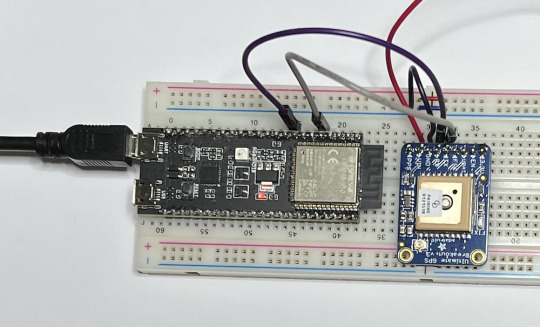
ESP32 Serial Ports - UART0, UART1, UART2 Access Using the Arduino IDE
The ESP32 has three UART interfaces: UART0, UART1, and UART2. They provide asynchronous, bidirectional communication at up to five Mbps. You can establish serial protocols using the appropriate breakout boards, such as RS232, RS422, RS485, USB, and more.
1 note
·
View note
Text
Design And Construction Of A Bi-Directional Visitors Counter
Design And Construction Of A Bi-Directional Visitors Counter
This Research Work is on Design And Construction Of A Bi-Directional Visitors Counter
Format: Ms Word Document
Pages: 75
Price: N 5,000
Chapters: 1-5
Get the Complete Project
Title Page
Certification/Declaration
Approval Page
Dedication
Acknowledgement
Abstract
Table of content
Chapter 1
Introduction
1:1 Introduction
1:2 Background of the Study
1:3 Statements of Problems
1:4 Objectives of…
View On WordPress
#8051#arduino#arduino bidirectional#assembly#at89c51#bidirectional#c#code bidirectional#counter#language automatic#microcontroller#pdf#pdf bidirectional#PHYSICS PROJECT TOPICS/MATERIALS#ppt bidirectional#programming bidirectional#Using#visitor
1 note
·
View note
Link
#arduino #arduinouno #irsensor #sensor #projects #electrcial #electronics #engineering #arduinoprojects
0 notes
Text
#ESP32CAM - Client Python 🐍 app to view WebServer photos 📸
#ESP32CAM – Client Python 🐍 app to view WebServer photos 📸
Hi ! Still learning with the ESP32 CAM board. In today’s post the scenario is simple: Create a client Python app to view remote photos from the ESP32 Cam Arduino device This is a super lower quality photo, but hey, still good enough ! This is a super simple Python and OpenCV app. This file contains bidirectional Unicode text that may be interpreted or compiled differently than what appears…

View On WordPress
0 notes
Text
Room Light Controller with Bidirectional Visitor Counter | Arduino
https://koliasa.com/room-light-controller-with-bidirectional-visitor-counter-arduino/ Room Light Controller with Bidirectional Visitor Counter | Arduino - https://koliasa.com/room-light-controller-with-bidirectional-visitor-counter-arduino/ #include LiquidCrystal ...
0 notes
Video
Ultrasonic sensor testing with Arduino Uno Board 3 PIN Ultrasonic Sensor PING Sensor ultrasonic distance sensor provides precise, non-contact distance measurements from about 2 cm (0.8 inches) to 3 meters (3.3 yards). It is very easy to connect to microcontrollers such as the BASIC Stamp®, Propeller chip, or Arduino, requiring only one I/O pin. The PING))) sensor works by transmitting an ultrasonic (well above human hearing range) burst and providing an output pulse that corresponds to the time required for the burst echo to return to the sensor. By measuring the echo pulse width, the distance to target can easily be calculated. Features & Specificatinos: Features No of Pins : 3 Range: 2 cm to 3 m (0.8 in to 3.3 yd) Burst indicator LED shows sensor activity Bidirectional TTL pulse interface on a single I/O pin can communicate with 5 V TTL or 3.3 V CMOS microcontrollers Input trigger: positive TTL pulse, 2 µs min, 5 µs typ. Echo pulse: positive TTL pulse, 115 µs minimum to 18.5 ms maximum. Pin Definitions: GND Ground (Vss) 5 V 5 VDC (Vdd) SIG Signal (I/O pin) Key Specifications: Supply voltage: +5 VDC Supply current: 30 mA typ; 35 mA max Communication: Positive TTL pulse Package: 3-pin SIP, 0.1” spacing (ground, power, signal) Operating temperature: 0 – 70° C. Electronics Curiosities Follow guys ����👇👇👇👇👇👇👍 @electronics_curiosities Follow guys 👇👇👇👇👇👇👇👍 @electronics_curiosities Follow guys 👇👇👇👇👇👇👇👍 @electronics_curiosities Suggest ideas for next post comments below 👇 Like Share Comment 👍 #electronics_curiosities #electronicspoint #diyelectronics #analogelectronics #digital_electronics #mechatronics #arduinouno #arduinofun #electronics #arduinonano #electrical #engineering #electronicsengineering #electronique #sensor #wires #electronicsengineering #circuitdesign #electronicsprojects #electronspark #electroniclovers #arduinolove #utsource #electronicsolutions #voltage #microcontroller #processor #computer #laptop #electricalengineering https://www.instagram.com/p/CGCJIa4BQNk/?igshid=18f7219nllzjz
#electronics_curiosities#electronicspoint#diyelectronics#analogelectronics#digital_electronics#mechatronics#arduinouno#arduinofun#electronics#arduinonano#electrical#engineering#electronicsengineering#electronique#sensor#wires#circuitdesign#electronicsprojects#electronspark#electroniclovers#arduinolove#utsource#electronicsolutions#voltage#microcontroller#processor#computer#laptop#electricalengineering
0 notes
Photo
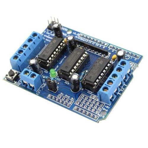
The Arduino L293D motor driver board is a board specifically designed to interface with the Arduino microcontroller platform. It uses the L293D motor driver IC to control the direction and speed of two DC motors. Some of the features of this board include:
Dual H-Bridge Circuit: The L 293D chip has two H-bridge circuits, which allow for bidirectional control of two DC motors.
Voltage Range: It operates on 4.5 to 36 V DC supply voltage.
Output Current: It can provide a peak output current of 600mA per channel, with a continuous current of around 300mA.
Pin Configuration: It has pins that are compatible with the standard headers on an Arduino board, making it easy to connect and control motors.
Protection: The L 293D has thermal protection and current limiting protection, making it safer to use with motors.
Board Size: The size of the board is typically small, making it suitable for use in small robotic projects.
This motor driver board is a convenient solution for controlling motors in Arduino projects, as it takes care of interfacing with the L 293D motor driver IC and provides a convenient interface to the user.
For more product detail Visit- https://www.campuscomponent.com/products/l293d-motor-driver-board/2208614000001862485
0 notes
Photo
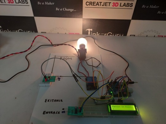
Automatic Room Light Controller With Bidirectional Visitor Counter Using Arduino. #AIMToInnovate/#Tinkerguru/ #atalinnovationmission/ #NITIAayog/#StemChange/ #RobotsMovie/https://goo.gl/Z2h9Ro
0 notes
Video
youtube
How to Control Room Light Automatically using Arduino | Home Automation using Arduino
Often we see visitor counters at stadium, mall, offices, class rooms etc. How they count the people and turn ON or OFF the light when nobody is inside? Today we are here with automatic room light controller project with bidirectional visitor counter by using Arduino Uno. It is very interesting project for hobbyists and students for fun as well as learning.
The project of “Digital visitor counter” is based on the interfacing of some components such as sensors, motors etc. with arduino microcontroller. This counter can count people in both directions. This circuit can be used to count the number of persons entering a hall/mall/home/office in the entrance gate and it can count the number of persons leaving the hall by decrementing the count at same gate or exit gate and it depends upon sensor placement in mall/hall. It can also be used at gates of parking areas and other public places.
0 notes
Video
instagram
DIY Bidirectional Person Counter Here is a very useful project for teachers by Maker Tutor on @youtube I’ll post a link to the full video in a story! #arduino #arduinoproject #arduinouno #diyproject #diy #diyelectronics #makertutor #nodemcu #innovation #counter #stem #stemeducation #makersgonnamake #maker #makerspaces (at Busan, South Korea) https://www.instagram.com/p/BwTA_o1B8JM/?utm_source=ig_tumblr_share&igshid=1urnih7u3lyef
#arduino#arduinoproject#arduinouno#diyproject#diy#diyelectronics#makertutor#nodemcu#innovation#counter#stem#stemeducation#makersgonnamake#maker#makerspaces
0 notes
Link
03100226 Breadboard Dedicated Power Module Compatible with 5V / 3.3V - Black + Yellow -----> $2.83 12X Lens Optical Magnification Telescope with Protective Back Case for Ipad MINI - Black -----> $25.56 3200 Static Color Identification Sensor Module for Arduino (Works with Official Arduino Boards) -----> $13.68 NRF905 Wireless Communication Transmission Module for Arduino (Works with Official Arduino Boards) -----> $5.77 Keyes Red/Green Color LED Common Cathode Module 3MM for Arduino (Works with Official Arduino Boards) -----> $1.97 Dog / Cat Pet Pooper Scoopers Clip Implement Pick up Folder with Paper - Random Color -----> $8.61 Cute Cartoon Cat Style Protective TPU Case with Screen Protector Guard for Iphone 4/4S - Black -----> $4.43 NF-8208 Communication Cable/Wire Tone Tracker Combo with Carrying Pouch -----> $64.85 NF-806B Communication Cable/Wire Tone Tracker Combo with Carrying Pouch (2 x 6F22 9V) -----> $43.71 NF-806R Communication Cable/Wire Tone Tracker Combo with Carrying Pouch (2 x 6F22 9V) -----> $43.96 Handheld Double Magnification Magnifier with 3-LED White Light (4 x AAA) -----> $12.44 Square White Cat with Pink Bow Tie Style Keychain - Silver + white -----> $2.40 Universal Positive and Negative Electrode Auto Identification Charging Dock with EU Adapter - Black -----> $4.99 Mini Cat Couple Figure Toy with Suction Cups - White + Black (Pair) -----> $4.45 Lovely Stealing Money Cat Coin Bank with Meow Effects - Brown (2*AA) -----> $19.78 Mini Funny Cat in the Bag with Sound Effects (3*LR44) -----> $2.39 CCTV via CAT-5 Twisted Pair Video Balun Transceivers with Extension Cable (Pair) -----> $5.23 CCTV via Cat-5 Twisted Pair Video Balun Transceivers with Extension Cable (Pair) -----> $5.99 Stress Relieving Electronic Cat Paw Keychain with Mew Effects -----> $4.15 Cute Cat Cloth Lint Remover with Brush (2*AA) -----> $7.51 2X Magnification Hand Free Glasses Style Magnifier Loupe with Clip -----> $2.96 Dream Catcher Long Necklace with Feather -----> $4.41 Dream Catcher Hook Tassel Earrings with Feather -----> $5.24 Trendy Cat Eye Presbyopic Eyeglasses with Rhinestones -----> $6.19 Mini Cute Cat Shape Bag Wallet Purse Billfold Burse with Zipper -----> $2.59 720P Mini Camera Dog Cat Pet Anti-lost Mini Cam With LCD Screen Video Camera -----> $27.17 5.5cm Pet Dog Cat Colorful Toy Ball Rainbow Rubber Ball Chewing Ball with Bell -----> $3.28 Animals Favorite Cat Play Mat Cat Play Tent Activity Center with Hanging Toys -----> $4.71 2.5x26 Magnification Binocular Telescope Kid Child Toy Gift with Neck Tie Strap -----> $2.86 HDMI Single Cat5e/6 Wall Plate Extender with Bi-Directional IR -----> $69.15 Cat Shape with Glasses Dial Japan Quartz Leather Watch for Women -----> $4.68 Men’s Bluetooth 4.0 Bidirectional Search Anti-Lost Location Short Wallet with PCBA Clip -----> $18.99 25x30 High Magnification Portable Telescope Night Vision Pirate Lens Barrel With Briefcase -----> $23.79 12V 8mm LED Dash Panel Indicator Light Lamp Red Blue Amber Green White with Wire -----> $3.72 Mini A8 GSM GPRS LBS Tracker Global Locator Real Time Car Kids Pet Tracking Device with SOS Button -----> $11.76 OBD2 OBD 16 PIN Auto Car GPS Tracker Locator with Web Vehicle Fleet Management System -----> $26.33 20mm Adjustable Stud Spring 9 inch Bipod Picatinny Rail With Standard Rail Mount -----> $27.62 Loskii H6 Wireless Voice Intercom Doorbell 300m Distance LED Indicator OutDoorbell Pair with InDoorbell -----> $23.13 Wireless Anti Lost Alarm Key Finder Locator Keychain Whistle Sound with LED Light -----> $3.15 Eye-Catching Red Finished 14 Inches Wide Industrial Single Light with Cage Guard -----> $74.51 Cat Pattern Long Sleeve Sweatshirt with Contrast Collar and Cuff -----> $19.42 3D Galaxy Glasses Cat Printed Long Sleeve Leisure Hoodie with Pocket -----> $27.23 Intricate Lattice Motif 3/5 Lights Tiffany Chandelier with Stained Glass Dome Shades for Living Room Restaurant -----> $129.09 Letter Cat Embroidered Faux Fur Long Sleeve Hoodie with Elastic Waist Shorts Co-ords -----> $25.92 Pleated Detail Hem Cat Embroidered Elastic Waist Mini A-Line Skirt with Belt -----> $21.70
0 notes
Text
Understandig IoT (Part 1)
Introduction
The Internet of Things, short “IoT” belongs, without a doubt, to the trend topics (not to say hype topics) of the present time. Who doesn’t know the studies predicting the explosion of internet connected devices in the near future (cf. e.g. [1] or [2])? But is there really something to these statements? Is there a new multi-billion dollar market just waiting around the corner? Or is this just another overhyped buzzword topic of which there are currently so many?
This question and others are being addressed in this post. In the first step, a general definition of the term IoT is established. Then, after defining the concept of innovation, the current development regarding IoT is placed in its historical context. Based on this, it is derived why the Internet of Things is actually an innovation. Afterwards, the different aspects belonging to the field “IoT” are elaborated and the problems addressed by this are discussed. The post is concluded by an outlook on potential future developments in this domain.
General description of IoT
In the most general sense, IoT describes the basic (bidirectional) interaction between a connected real world interface and an arbitrary logical entity — e.g. a component of a traditional IT infrastructure — or another real world interface. It’s a common misunderstanding that the term IoT is restricted to hardware devices with low computing power like e.g. microcontroller units (MCUs) or single-board computers like the Raspberry Pi. Although this impression can easily be implied by their strong dissemination in high-profile maker projects (e.g. through blog posts, social media, etc.), they still only make up for a fraction of the entirety, comparable to how deep learning is a part of AI yet AI is not solely deep learning.
Instead, IoT in its core comprises the whole field layer (from the German term “Feldebene”; the entirety of devices interacting with the (real world) environment). Besides the aforementioned low-power devices (incl. traditional connected sensors / actors) this furthermore e.g. includes voice assistants like Amazon Echo, household objects like a “smart�� (whatever that may mean) freezer or — in a more industrial context — even connected programmable logic controllers (PLCs) and (partly) robots.
This description may be interpreted as a general definition of the term IoT. In order to be able to answer the questions formulated beforehand, however, this alone is not sufficient. Therefore it is necessary to immerse deeper in the topic and to look at the underlying concepts.
The innovation cycle
To understand the concepts underlying IoT, it is first necessary to understand the evolutionary technical process preceding it. For this, a general definition of the concept of innovation is required in the first place.
In contradiction to the generally widespread interpretation, innovation does not mean to create something completely new from ground up. A historical view on mankind’s great technological achievements shows that it is rather a process of recombining existing knowledge and / or resources with slight modifications to fit an existing problem at the right time. The latter is an important, often neglected factor as it is paramount for if a novelty is going to disrupt existing structures or — to make use of a figurative phrase — if it is going to sink into obscurity as the world isn’t ready for it (yet). In general, there are several implications that have to be met (at least partly) for an innovation to develop clout, amongst others maturity of the technological field, accessibility of the technology itself and the size of the sphere of influence of the problem that can be solved by this novelty. The first two mainly influence the general prevailment resp. acceptance of the innovation, the latter is decisive for the disruptiveness of the respective development.
A good example to further illustrate this coherence is provided in form of the so-called “Industrial Revolutions”. If you have a look at the past developments since the mid-18th century when the first of these shifts took place, one can find the same repeating pattern whenever a disrupting technological breakthrough was achieved.
It always starts with technological advancement in a (new) field offside the industrial mainstream. The domain continues to dwell on its own until it advances past a certain level, usually the moment when it becomes ready for usage in an industrial context (maturity) or when its complexity deceeds a certain level so that the usage doesn’t require specific expert knowledge anymore (accessibility). At this point, other industries start to become aware of the existence of the novelty and start to examine their own field for problems that could be solved by this or for new business models that become possible. In that case, the new branch is either assimilated or merged into the value chain. And if the resonance across the field as well as the impact this has upon the further development is high enough (problem’s sphere of influence), one starts to speak of a “revolution”. In consequence, many new fields and possibilities open up and a period of enormous technological advancement begins. This is mostly accompanied by a social disruption as a reaction to the novelties and their influences on the daily life. After the era of fast development follows a technological recession when the novelties start to settle down. This could also be called the integration phase because this is the time when all the initial works and concepts from before are fine tuned and integrated across the board. It’s usually this stage when new ideas and concepts, enabled and catalyzed by the advancement from the previous revolution, begin to emerge in the shadows. The cycle starts anew.
This innovation cycle can be observed at many points throughout history. It began with the mechanization that enabled industrial use of steam machines in the mid- to late-18th century. As a consequence, especially the metal industry advanced enormously which then again facilitated the uprising of the railroad and electrical industries that lived an existence in the shadows (resp. in theory and R&D) up until then. This led to the second revolution in the late 19th century which brought upon the beginnings of what is know as globalization today as well as the electrification of social and productive organization. And lastly, there’s the most “recent” third industrial revolution in the mid 1900s that marked the shift from mechanical and analogue to digital electronics and that was a (more or less) direct result of the uprising of the semiconductor industry and thus of the preceding revolution. The most fitting description for this time would probably the “era of digitization and automation“.
IoT & Innovation
To summarize the above, so far a general definition of the concept of innovation has been established, the differences between normal and disruptive innovations have been analyzed and some examples in the form of the so called “Industrial Revolutions” have been discussed.
Looking at the outcome of the last revolution, what one will find is that there were basically two major sectors afterwards that overshadowed the rest and that determined the direction of further technological progress: the digital and the (consumer) electronics industry. Yet, it should be noted that the success of the latter was at least partly chained to that of the former as it provided the interface to the content that was produced by the software developers. So it’s probably okay to say that it was mainly the IT industry that was the driving force in the late-20th century.
For quite some time, the software branch developed on its own. The ambitions to fully exploit the potential of the internet predominated pretty much everything else. Additionally, hardware was rather expensive in the beginning, so it didn’t seem very profitable to make use of it any more than absolutely necessary. The result were effects like the dot-com bubble in the early 2000s as well as a complete redistribution of power among the big players with the uprising of companies like Yahoo, Google or MySpace and later Facebook, Amazon & co. But at the same time, the electronics industry didn’t just sit still. While the software branch fought over the supremacy over the internet, the exponentially increasing demand for computers, smartphones, etc. led to a constant advancement in this sector. Quantities increased while size and prize of the components dropped dramatically over the years. Figuratively speaking: The same (or even more) computing power that cost thousands of dollars about two or three decades ago is now available for under 10$ in form of e.g. an Arduino or a Raspberry Pi Zero. At the same time, connectivity in general increased massively as well as a direct necessity for the users to be able to access the content developed by the emerging software industry.
Now, with regard to the above definition of the term innovation, one can say that today mankind has arrived at a point in development where the requirements of maturity and accessibility are definitively satisfied. Computing power has become generally available (e.g. in the cloud), hardware costs have declined massively and a huge software ecosystem with prefabricated solutions for almost any common use case has been established in the meantime. By combining these individual pieces it becomes possible to deploy many of the technological advancements from the software industry that humanity has become affiliated with over the last ~30 years from private computers and smartphones, etc. to devices, machines, buildings, everything and connect them among each other or with the internet. This alone already qualifies this newly emerging development, also known as IoT, as an innovation with a high probability of prevailability.
Even so, what’s left to discuss is the problem space that is solved by this development resp. the need that is covered by it as this is deciding for the clout and thus the disruptiveness of an innovation. This is going to be the topic of the second part.
Der Beitrag Understandig IoT (Part 1) erschien zuerst auf codecentric AG Blog.
Understandig IoT (Part 1) published first on https://medium.com/@koresol
0 notes