#buzzer module
Explore tagged Tumblr posts
Visit Tumblr Blog
Explore Tumblr blogs with no restrictions, modern design and the best experience.
Last Seen Tumblr Blogs


Fun Fact
China blocked Tumblr because of pornography and censorship problems in 2013.
Text
youtube
#AC voltage measurment#arduino nano#voltage sensor#ZMPT101B#TM1637 4 Digit Seven Segment Display Module#TM1637#buzzer module#arduino IDE#IOT#smart city#smart home#internet of things#Youtube
1 note
·
View note
Text
Unveiling the Melodious Marvel: The Buzzer Speaker Module
In the vast realm of electronic components, one unsung hero stands out for its simplicity yet immense utility — the buzzer speaker module. This unassuming device has found its way into countless gadgets, alarms, and interactive projects, adding a touch of auditory magic to our technological landscape.
The Humble Beginnings
The journey of the buzzer speaker module begins with a simple yet ingenious concept. Imagine a tiny device that can transform electrical signals into audible sounds, creating a symphony of beeps, chirps, and melodies. That’s exactly what the buzzer speaker module does. At its core, it’s a small electronic component designed to produce sound when an electric signal is applied.
The Sound Symphony
What makes the buzzer speaker module truly fascinating is its ability to turn mundane electrical impulses into a delightful auditory experience. With a range of frequencies and tones, this electronic marvel can produce everything from attention-grabbing alarms to whimsical tunes. It’s the musical conductor of the electronic orchestra, adding a touch of harmony to the beeps and boops of our gadgets.
Where You’ll Find It
Step into the world of everyday electronics, and you’re likely to encounter the buzzer speaker module more often than you realize. From your morning alarm clock to the electronic doorbell that announces a visitor, these modules are embedded in a variety of devices that make our lives easier and more efficient.
Think about those interactive museum exhibits that captivate visitors with immersive audio experiences or the friendly chirps of a digital thermometer letting you know your pizza is perfectly cooked. It’s the buzzer speaker module that brings these devices to life, engaging our senses in ways that go beyond the visual.
DIY Delight
One of the most exciting aspects of the buzzer speaker module is its popularity among electronics enthusiasts and DIY hobbyists. With a basic understanding of electronics and a creative spark, anyone can incorporate this tiny musical maestro into their projects. Whether it’s a homemade alarm system or a quirky musical instrument, the buzzer speaker module invites experimentation and innovation.
The Future of Sound
As technology advances, the humble buzzer speaker module continues to evolve, becoming more versatile and sophisticated. With improvements in design and functionality, we can expect to see these modules taking on new roles in emerging technologies.
Imagine a future where smart homes communicate with residents through melodic tones, or wearable devices provide feedback through subtle yet distinctive sounds. The buzzer speaker module could play a pivotal role in making our interactions with technology not just efficient but also delightful.
In the vast landscape of electronic components, the buzzer speaker module may seem like a small player, but its impact is anything but insignificant. From waking us up in the morning to alerting us to important events, this unassuming device has become an integral part of our daily lives. As we continue to embrace the possibilities of technology, let’s not forget to appreciate the charm of the buzzer speaker module — a true unsung hero in the symphony of electronic innovation.
0 notes
Text
Ecosystem Hell rw au x Elemental Iterator Local Group!
i swear this is interesting chat. i’m really proud ‘o these sketches 🫶 and writing! i’m sprinkling in some character psyche too so oooo you wanna read this ooooo👻👻
so. @rna-world / tarigon’s au “where iterators become hybrids of rw creatures that fit them and then are forced to survive in the wacky wild as organisms” idea is cool. very cool. cool enough for me to have reblogged nearly all of it 3 weeks back. and now its coming back to me… oh goodness gracious
so!! in this post! i’m going to scribble down my thoughts on these barely-shared ocs of mine, and how they’d be integrated into which animal and survive in what way. exciting! LETTUCE BEGIN:
reblogs>likes

these are the first few i came up with! was in a little funk so i wasn’t proud of them at the time, but thats changed ^_^
DeeDee isn’t related to the group at all—his design was just a brainwave i needed to get out. but the others! oh boy the others:
Weaving Currents is a ghostlike fusion with the very overseer that lends him his voice. this body enables soundless stealth and camouflage through translucent flesh. i wanted to emulate the deep sea vibe he has goin for him, which was especially built upon with his redesign! Currents is tricky and slinky, working as the perfect assistant and spy in Shadows’ search for power. and his peculiar quest for one specific little “traitorous” guy.
Six Colorful Strings (behold, our timid protagonist!) is a blue lizard. she is fragile and agile and always carries a weapon. whatever sort of process she underwent to become this was prepared with haste, and she’s still getting used to the new systems. and this rapid change and cell death has her rot spiking in activity. now, since a risk of spread is now prominent through coughing fits, she has attempted a makeshift mask out of an old cloth scrap. i honestly wanted to emulate some of tarigon’s AGS-orangeliz vibes through Strings here because. hello? peak??
Seven Even Windy Cycles always wanted to fly away. the wish arose from past circumstances, but remained as a whimsical dream. his can is placed in the run-down suburbs of abandoned architecture that crawl with bugs and bats after his weather modules go…missing? perhaps it was the bugs and the bats that he likes to watch. (insert segue) so he got squidcada-beamed because i said so. there was a running sorta-vulture mask idea that made it halfway, but he’s so underdeveloped as a fella that i need to straighten a few things up first.
Broken Gears over Grinding Gravel is definitely the techhead here. integrated so heavily into his work that anything he’s not good at he’s just accepted as failure. and that’s not a good mindset to have in the wild, but who cares! he’s in the highchair now. and the two things he’s good at are self preserval and working his mech. Gears is a tired old father who tries to forget regret—especially the involvement he had with Shadows’ greed. little beast grew out of control. what was he supposed to do??
Deeper Darker Shadows is the main antagonist and a persistent one at that! with his quest to rejuvenate his disordered systems with other iterators’ rarefaction cells, and having succeeded multiple times thus far, he’s earned the status of something to be feared. however he’s the brains of the operation, not the brawn. especially with a recent development lending him a maw-like wound in his face. giving him all the more reason to seek power to overcome the hurt. with the hushed judgmental fear all around his name, he’d have to appear as something imposing in the wild—right? LOUD INCORRECT BUZZER. this man is a stinky younger brother who’s too self entitled for his own good. but his looming presence is like a shadow (heh) despite the hidden truth. so he also gets bugbeamed. jackass! hope he isn’t too stupid and gets himself killed. a second time.
below is even more character sketches for a select few that i’m extremely proud of. eat up folks!


if you enjoyed the concept of iterators surviving in the wild itself, i’d consider checking out tarigon’s incredible art and thoughts over on zeir blog! featuring both canon and iterator logs interpretations unlike anything i’ve ever seen. there’s a reason i reblogged it all so many times 😔/positive
#elementaliterator#ecoh#ei x ecoh#<< tarigon’s tag for ecosystem hell. i’ll remove it if asked#iterator oc#iterator#rw iterator#rain world iterator#pen&pencilparade#that is the longest goddamn roll of the thunder i have ever heard in my goddamn life#tell if you’d rather not be @ed tarigon! i did it to notify and link you but i’ll respect if that’s a no-go#rainworld iterator#ei-ecoh
6 notes
·
View notes
Text
DIY Laser Tripwire Security System Using Arduino

The project consists of a laser module that continuously emits a beam aimed at a laser receiver sensor. When an object (such as a person) obstructs the laser, the receiver detects the interruption and triggers an alarm via a buzzer. This system is ideal for securing doorways, hallways, or any restricted area.
COMPONENTS REQUIRED
Arduino Uno
Laser LED Module
Laser Receiver Sensor Module
Buzzer
Jumper wires
Breadboard
Circuit Diagram

CODE
#define LASER_PIN 7
#define RECEIVER_PIN 8
#define BUZZER_PIN 9
void setup() {
pinMode(LASER_PIN, OUTPUT);
pinMode(RECEIVER_PIN, INPUT);
pinMode(BUZZER_PIN, OUTPUT);
digitalWrite(LASER_PIN, HIGH); // Laser ON
Serial.begin(9600);
}
void loop() {
int status = digitalRead(RECEIVER_PIN);
if (status == 1) { // If laser beam is blocked
Serial.println("⚠️ Intruder Detected!");
digitalWrite(BUZZER_PIN, HIGH);
} else {
Serial.println("✅ Area Secure");
digitalWrite(BUZZER_PIN, LOW);
}
delay(500);
}
youtube
9 notes
·
View notes
Text
Top 5 Must-Have Accessories for Every Electrical Panel

An electrical panel is the nerve center of any low-voltage power distribution system — responsible for delivering electricity safely and efficiently to various circuits. While the breakers and busbars often take the spotlight, it’s the accessories that enhance functionality, safety, monitoring, and reliability. Whether you’re an OEM, panel builder, or facility manager, equipping your panels with the right accessories can make all the difference.
In this article, we explore the top 5 must-have accessories for every electrical panel, based on industry best practices and real-world applications.
1. Cable Ducts and Trunking Systems
Purpose:
Cable ducts (also called wiring ducts or trunking) are essential for organizing and routing internal panel wiring. They prevent clutter, minimize the risk of short circuits, and make future maintenance more manageable.
Key Benefits:
· Improved safety through wire separation and insulation
· Neat, professional layout that meets electrical standards
· Ease of troubleshooting during inspections or servicing
Common Types:
· Slotted PVC ducts
· Halogen-free wiring ducts (for safety-critical environments)
· Flexible ducts for tight corners
Pro tip: Always select ducts with sufficient space for future cable additions — typically 20–30% free space is recommended.
2. Terminal Blocks and Marking Systems
Purpose:
Terminal blocks serve as connection points between internal and external wiring, ensuring a secure and modular setup. Combined with proper marking systems, they allow clear identification of circuits and functions.
Key Benefits:
· Safe and reliable wire termination
· Clear labeling for faster diagnostics
· Scalable for expansions and upgrades
Essential Variants:
· Feed-through terminal blocks
· Grounding terminals
· Fuse terminal blocks
· DIN-rail mounted marking strips or markers
Tip: Use color-coded terminals and labels according to IEC or local wiring codes for better clarity.
3. Panel Meters and Monitoring Devices
Purpose:
Modern electrical panels are not just passive distribution points — they are smart monitoring stations. Panel meters and current monitoring devices help track voltage, current, frequency, and power consumption.
Key Benefits:
· Real-time data for preventive maintenance
· Improved energy efficiency
· Quick response to load imbalance or faults
Popular Options:
· Digital voltmeters and ammeters
· Multi-function energy analyzers
· Load monitoring relays
Advanced choice: Consider smart monitoring units with Modbus or Ethernet communication for integration with BMS or SCADA systems.
4. Control and Signaling Devices
Purpose:
Control and signaling accessories like push buttons, selector switches, and pilot lights are critical for human-machine interaction. They allow operators to control, signal, and monitor operations within or from the front of the panel.
Key Benefits:
· Improved operator control and feedback
· Quick visual status indication
· Enhanced safety through emergency stop functions
Must-Have Components:
· Illuminated push buttons (Start/Stop)
· Pilot lights (for voltage presence or fault status)
· Emergency stop buttons
· Audible buzzers for alerts
Best Practice: Use IP65-rated front-panel devices for industrial environments to ensure durability and resistance to dust and moisture.
5. Surge Protection Devices (SPD)
Purpose:
Electrical surges — whether from lightning or switching operations — can damage panel components or connected equipment. SPDs protect against transient over voltages.
Key Benefits:
· Prevents costly downtime and equipment failure
· Increases the lifespan of electronics and controls
· Meets compliance with IEC 61643 or UL 1449 standards
Selection Tips:
· Choose SPDs according to system voltage (230V/400V) and risk level
· Type 1 for external surge protection, Type 2 for internal panel protection
· Consider combined Type 1+2 for comprehensive safety
Smart move: Pair SPDs with monitoring modules to track surge counts and SPD health.
Final Thoughts
When designing or upgrading your electrical panel, these five accessory categories are not just optional — they’re essential. They improve safety, functionality, compliance, and operational efficiency. Whether you’re building panels for industrial, commercial, or residential applications, investing in high-quality accessories will yield long-term benefits.
At Daleel Trading, we supply trusted low-voltage switchgear accessories from leading brands like Civaux — ensuring your panels are equipped with components that meet international standards.
Ready to upgrade your panel accessories?
Contact us today to learn more about our product range or request a consultation with our technical team.
6 notes
·
View notes
Text

I've been seeing some people being confused in the notes so,,,
While modern radios have way more elements than this, if the signal is strong enough that's technically all you need. ... okay and some wire i suppose.
Because radio waves are electromagnetic and they oscillate, they create a small current in a conductor (that's induction!). The diode together with a person holding it serves to "decode" the radio signal. The diode rectifies it and the person, acting as an antenna, both picks up the signal and acts as a crude low pass filter. That's all you need to decode an AM (amplitude modulated) signal. With the magnet and tin can, you can make a speaker to then listen to that decoded signal. Mind you that this would be an untuned radio, picking up many frequencies at the same time. You'd hear them overlap.
I intentionally said AM and not FM because the latter is not that easy to decode and would need additional materials.
In this post I'm slightly exaggerating how easy it'd be to listen to a signal like that with some quality but technically with a strong signal it's absolutely possible and even if you do add some more elements to make the signal clear and specific you still wouldn't need an additional power source. The only thing an AM radio typically needs a power source for is a sound amplifier, but if you use high impedance (2k Ohm) headphones you don't need that. The catch is that these can be hard to find these days, but you can still make them out of e.g. piezoelectric buzzers or indeed a magnet and a tin can.
AM radio is like literal magic. There is music all around us that we can't hear, and to hear it you just have to tap a crystal (diode) to the earth and listen to it with another magic rock (magnet) and a tin can. You dont even need electricity to make it work because this music around us is literally all the power you need. Oh and at night when the sun has set, the light of the day gets replaced by MORE music because the signals can travel further at night. This is magic. If you even care.
30K notes
·
View notes
Text

JRC NCE-6255A EXTERNAL BUZZER
JRC NCE-6255A EXTERNAL BUZZER is a high-quality buzzer manufactured by JAPAN RADIO CO.,LTD. This model, NCE-6255A, is designed to provide audible alerts in various applications, making it an essential component for communication systems. The EXTERNAL BUZZER is known for its reliability and durability, ensuring long-term performance in demanding environments.
Equipped with INMARSAT technology, the JRC NCE-6255A External Buzzer offers seamless integration with satellite communication systems. The CAB-580B buzzer display module enhances the functionality of this device, providing clear and distinct alerts when triggered. With the BUZZ DISP PCSC20568 part number, users can easily identify and replace components as needed, ensuring smooth operation at all times.
0 notes
Text

ARM Embedded Controllers ARMxy in Building Fire Protection Systems
Main Application Scenarios
Fire Detection and Alarming: ARM controllers integrate sensors (e.g., smoke, temperature, gas sensors) to monitor environmental data in real-time, using algorithms to assess fire risks and trigger alarms.
Fire Equipment Control: Manage fire pumps, sprinkler systems, fire doors, smoke exhaust fans, etc., ensuring rapid response during a fire.
Communication and Networking: Support multiple communication protocols (e.g., Modbus, CAN, Ethernet, 4G, Wifi) for connectivity with fire control centers, cloud platforms, or other smart devices.
Data Processing and Storage: Process large amounts of sensor data and log events for post-incident analysis and system optimization.
Human-Machine Interaction: Drive displays or touchscreens to provide status monitoring and operation interfaces for fire protection systems.
Emergency Power Management: Manage backup power sources (e.g., UPS or batteries) to ensure system operation during power outages.
Advantages of ARM Embedded Controllers ARMxy series
High Performance and Low Power Consumption: ARM Cortex-M series (e.g., Cortex-M4, M7) or Cortex-A series offer strong computing power while maintaining low energy consumption, ideal for continuous operation in fire systems.
Rich Peripheral Support: ARMxy series Integrated RS485, GPIO, DI, DO, AI, AO. RS232, CAN, RTD, etc., facilitate connections to various sensors and actuators.
Real-Time Capability: Support real-time operating systems (RTOS, e.g., FreeRTOS, uC/OS) to ensure low-latency fire detection and response.
Scalability: ARMxy series supports modular design, enabling easy system upgrades or feature expansions.
Cost-Effectiveness: ARM chips are relatively affordable, suitable for large-scale deployment in building fire systems.
Security: Support encryption modules and secure boot to prevent malicious tampering, ensuring system reliability.
Typical Implementation Cases
Smoke Alarm System: Use ARM Cortex-A7 controllers BL330 with smoke sensors, collecting data via DI/AI to trigger buzzers or networked alarms.
Smart Fire Hydrant Monitoring: ARM controllers monitor hydrant water pressure and status, uploading data to the cloud via Ethernet, 4G or WiFi.
Building Fire System Integration: Cortex-A55 controllers BL410 running Linux integrate video surveillance, fire alarms, and evacuation guidance for comprehensive management.
Development Considerations
Reliability: Fire systems require 24/7 operation; select industrial-grade ARM chips to ensure high temperature resistance and anti-interference.
Redundancy Design: Include backup controllers or communication channels to prevent single-point failures.
Certification Standards: Ensure compliance with fire protection standards.
Power Optimization: Use sleep modes or dynamic frequency scaling to reduce energy consumption and extend device lifespan.
Software Security: Regularly update firmware to mitigate potential cyberattacks.
Summary
ARM embedded controllers, with their high performance, low power consumption, and flexibility, have become core components of building fire protection systems. Through proper chip selection and design, they enable efficient and reliable fire detection, equipment control, and emergency response, significantly enhancing building fire safety.
0 notes
Text
High Visibility LED Beacon and Signal Tower Lights | Qlight

Qlight’s signal tower lights and beacon lights are designed to provide clear, reliable visual signaling in industrial environments, improving safety, process control, and communication on site.
LED stack lights: Qlight’s modular LED stack lights offer high visibility and customizable signaling for industrial environments. With tool-free assembly, each module – including lens, buzzer, and bracket – can be easily replaced or reconfigured. They support various control options such as CAN protocol, RS 485 protocol, USB, and wireless communication.
Available in multiple sizes and IP ratings, ideal for automation, logistics, and manufacturing sites.
LED Beacon Lights: Compact and high-intensity, Qlight’s beacon lights deliver 360-degree visibility to alert operators of status changes, hazards, or emergencies. These beacons come in various mounting styles (wall, surface, and pole) and configurations, such as rotating, strobe, flashing, and steady operation.
Both product ranges are engineered for high durability, with IP-rated waterproof and dustproof models, vibration resistance, and long-life LED technology. Qlight also offers explosion-proof beacons for hazardous areas and marine-grade models designed to withstand salt, vibration, and moisture, ideal for shipbuilding and offshore use.
These visual signaling solutions are widely used across factory automation, machinery, logistics, marine, automotive, semiconductor, and petrochemical industries, ensuring clear visual and audible communication in any operational setting.
If you are looking for high visibility LED beacon and signal tower lights, you can get them from Qlight.
Click here to contact Qlight.
View more: High Visibility LED Beacon and Signal Tower Lights
0 notes
Text
ESP32-C3 Mini: Die perfekte Basis für eine moderne Timerschaltung

In einem früheren Beitrag habe ich mit der Arduino-gestützten Eieruhr bereits eine flexible Countdown-Anzeige mit akustischem Alarm vorgestellt. Die ursprüngliche Version, die ich auf meinem Blog unter diesem Link veröffentlicht habe, basierte auf einem klassischen Arduino. Doch nun wird es Zeit für ein Upgrade: Der ESP32-C3 Mini bietet nicht nur mehr Leistung mit seinen 160 MHz, sondern bringt auch WiFi- und Bluetooth-Konnektivität mit – und das in einem äußerst kompakten Format. https://youtu.be/5CGeBJfi6Gc Die Portierung der bestehenden Arduino-Schaltung auf den ESP32-C3 Mini war erstaunlich einfach, da dieser ebenfalls in der Arduino IDE programmiert werden kann. Der eigentliche Fokus lag jedoch darauf, die Schaltung auf eine eigene Platine (PCB) zu bringen, um sie für ein bevorstehendes Event im JFZ Schöningen einsatzbereit zu machen.
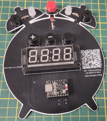
In diesem Beitrag zeige ich, wie die Timerschaltung mit dem ESP32-C3 Mini realisiert wurde, welche Anpassungen notwendig waren und wie die finale Version als fertige Platine umgesetzt wurde.
Warum der ESP32-C3 Mini besser als ein Arduino ist
Zunächst einpaar Gründe warum der ESP32-C3 Mini besser als ein Arduino ist: ✔ WiFi & Bluetooth integriert – Kein extra Modul nötig, ideal für IoT. ✔ Mehr Leistung & Speicher – 160 MHz, 384 KB RAM vs. 16 MHz, 2 KB RAM beim Arduino. ✔ Energieeffizient – Sleep-Modi für geringen Stromverbrauch. ✔ Vielseitigere GPIOs – Mehr analoge Eingänge, PWM, SPI, I2C, UART gleichzeitig nutzbar. ✔ Moderne Programmierung – Neben der Arduino IDE auch MicroPython & ESP-IDF unterstützt.
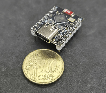
ESP32-C3 Super Mini
Benötigte Bauteile für die Timerschaltung
Für den Aufbau der Schaltung werden folgende Komponenten benötigt. Diese ermöglichen eine einfache Umsetzung und sind flexibel auf einem 800-Pin-Breadboard testbar. - 1x ESP32-C3 Mini – Der Mikrocontroller als Steuerzentrale - 4x Taster mit K��pfen – Zur Steuerung der Timer-Funktionen - 1x 3mm LED mit 220-Ohm-Vorwiderstand – Statusanzeige - 2x 5mm LED mit 220-Ohm-Vorwiderstand – Visuelles Feedback beim Alarm - 2x Piezo-Buzzer – Akustischer Signalgeber - diverse Breadboardkabel – Zur Verbindung der Komponenten - 1x 800-Pin-Breadboard – Für eine flexible Verdrahtung Hinweis von mir: Die mit einem Sternchen (*) markierten Links sind Affiliate-Links. Wenn du über diese Links einkaufst, erhalte ich eine kleine Provision, die dazu beiträgt, diesen Blog zu unterstützen. Der Preis für dich bleibt dabei unverändert. Vielen Dank für deine Unterstützung!
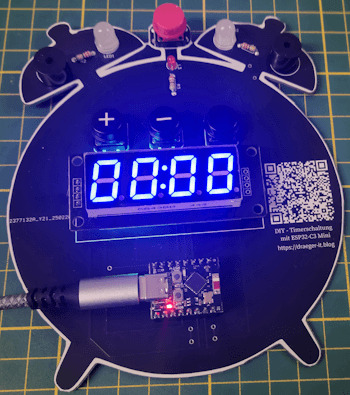
Timerschaltung am Schaltung am ESP32-C3 Mini im Detail
Nachfolgend die Timerschaltung am ESP32-C3 auf einem Breadboard.
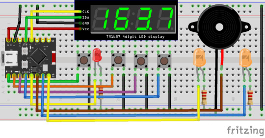
ESP32-C3 Mini - Countdown Schaltung Bauteil / PinESP32-C3 Mini4fach 7 SegmentanzeigeCLK > 3 (GPIO3) SDA > 4 (GPIO4) GND > GND VCC > 5VTaster - Start / Stopp5 (GPIO5)Taster - Plus6 (GPIO6)Taster - Minus7 (GPIO7)Taster - Select8 (GPIO8)LED 120 (GPIO20)LED 221 (GPIO21)Status LED9 (GPIO9)Piezo Buzzer - links10 (GPIO10)Piezo Buzzer - rechts2 (GPIO2) Pinout des ESP32-C3 Mini Nachfolgend findest du den Aufbau des ESP32-C3 Mini, der dir hilft, die richtigen Pins für deine Schaltung schneller und einfacher zu identifizieren. Eine klare Übersicht der GPIO-Belegung erleichtert die Verdrahtung und reduziert Fehler beim Anschluss der Komponenten.
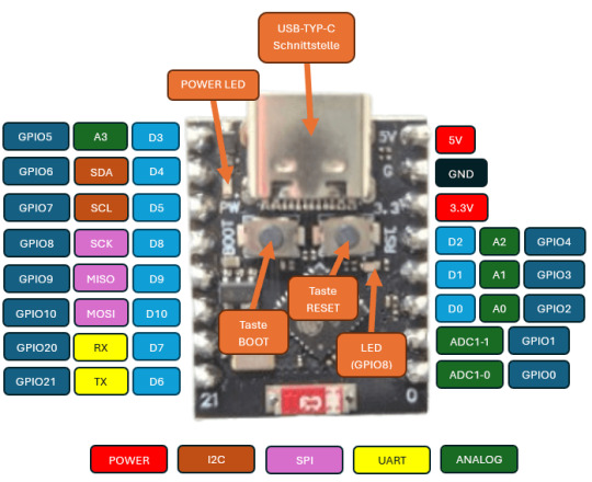
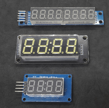
ESP32-C3 Pinout Falls du spezielle Funktionen wie PWM, I2C, SPI oder UART nutzen möchtest, lohnt sich ein Blick auf die multiplen Belegungsmöglichkeiten der Pins. Unterschiedliche - 4fach 7Segmentanzeigen Es gibt verschiedene Arten von 7-Segment-Anzeigen auf dem Markt. Einerseits gibt es kompakte, einfache Modelle, andererseits größere Varianten mit farbigen Segmenten. Für dieses Projekt entscheide ich mich für die größere Version, da sie nicht nur besser lesbar ist, sondern durch die unterschiedlichen Farben auch optisch ansprechender wirkt und das Projekt aufwertet.
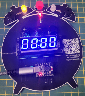
Ausbau einer LED In der Schaltung kommen drei LEDs zum Einsatz, die sich durch ihre hohe Leuchtkraft und lange Lebensdauer auszeichnen. Sie dienen nicht nur als Statusanzeige, sondern ermöglichen auch eine visuelle Rückmeldung über den aktuellen Betriebszustand der Timerschaltung. Die LEDs werden über einen GPIO-Pin des ESP32-C3 Mini angesteuert und mit einem 220-Ohm-Vorwiderstand in Reihe geschaltet, um den Stromfluss zu begrenzen und die Lebensdauer der LEDs zu erhöhen. Durch diese Beschaltung ist sichergestellt, dass die LEDs effizient betrieben werden, ohne den Mikrocontroller zu überlasten. Beim Einbau einer LED ist darauf zu achten, dass sie richtig gepolt angeschlossen wird. Die Kathode (Minuspol) wird mit dem Vorwiderstand verbunden, der anschließend an GND führt. Die Anode (Pluspol) hingegen wird direkt mit dem entsprechenden GPIO-Pin des ESP32-C3 Mini verbunden. Eselsbrücke: Die Kathode erkennt man am kürzeren Bein der LED.

Aufbau einer LED Falls du mehr über die Funktionsweise und den Anschluss von LEDs erfahren möchtest, findest du eine detaillierte Erklärung auf der Seite "Bauteile: Leuchtdiode (LED)", wo ich dieses Bauteil ausführlich vorstelle.
Programmieren in der Arduino IDE
Wie bereits erwähnt, habe ich dieses kleine Projekt zuvor für den Arduino entwickelt und programmiert. Dadurch war die Portierung auf den ESP32-C3 Mini relativ unkompliziert – es mussten lediglich die Pinbelegungen angepasst werden. Eine zusätzliche Optimierung bestand darin, die Start- und Stopp-Funktion auf einen einzigen Taster zu legen, anstatt zwei separate Taster zu verwenden. Dadurch spart man nicht nur einen GPIO-Pin, sondern macht die Bedienung auch kompakter und effizienter. Dies ist besonders vorteilhaft, da der ESP32-C3 Mini im Vergleich zu einem klassischen Arduino weniger verfügbare GPIOs hat. Programm: Timerschaltung am ESP32-C3 Mini in der Arduino IDEHerunterladen fertiges Programm für eine Timerschaltung am ESP32-C3 Mini /* * Autor: Stefan Draeger * Webseite: https://draeger-it.blog * Beitrag: https://draeger-it.blog/esp32-c3-mini-die-perfekte-basis-fuer-eine-moderne-timerschaltung/ * * Beschreibung: * Diese Firmware steuert eine Timerschaltung mit einer 7-Segment-Anzeige (TM1637), * Tastern zur Zeiteinstellung, LEDs zur Statusanzeige und einem akustischen Alarm über einen Buzzer. * Die Zeit kann in Sekunden oder Minuten eingestellt und per Start/Stopp-Taste gesteuert werden. * * Funktionen: * - Anzeige der verbleibenden Zeit auf einer TM1637 7-Segment-Anzeige * - Steuerung der Zeit über Taster (Erhöhung/Verringerung in Sekunden oder Minuten) * - Akustischer Alarm nach Ablauf des Timers mit abwechselnden LED-Signalen * - Speicherung und Aktualisierung des Timers in der Loop * - Start/Stopp-Funktion für den Timer */ #include // Bibliothek für 7-Segment-Anzeige TM1637 #include // Bibliothek für die Taster-Entprellung // Definition der LED-Pins #define led1 20 #define led2 21 // Definition der Pins für die 7-Segment-Anzeige (TM1637) #define segmentanzeige_CLK 3 #define segmentanzeige_DIO 4 TM1637Display display(segmentanzeige_CLK, segmentanzeige_DIO); // Anzeige-Objekt erstellen // Definition der Taster-Pins #define tasterStartStopp 5 #define tasterPlus 6 #define tasterMinus 7 #define tasterSelect 8 // Taster-Objekte für die Entprellung Bounce bceTasterStartStopp = Bounce(); Bounce bceTasterPlus = Bounce(); Bounce bceTasterMinus = Bounce(); Bounce bceTasterSelect = Bounce(); // Definition der Pins für Buzzer und Status-LED #define buzzerLeft 10 #define buzzerRight 2 #define statusLed 9 // Variablen für die Timer-Logik unsigned int timeAuswahl = 0; // Auswahlmodus für Zeit (Sekunden/Minuten) unsigned int seconds = 0; // Aktuelle Zeit in Sekunden const unsigned int PAUSE = 1000; // Zeitintervall für Timer-Update (1 Sekunde) const unsigned int PAUSE_ALARM = 250; // Zeitintervall für Alarmton unsigned long lastAction = 1L; // Zeitstempel für letzte Aktion bool clockStarted = false; // Timer läuft oder nicht bool clockAlarm = false; // Alarmstatus bool lastStateLED = false; // Zustand der LEDs für Alarm void setup() { // Setzt die Pin-Modi für LEDs, Buzzer und Status-LED pinMode(led1, OUTPUT); pinMode(led2, OUTPUT); pinMode(buzzerLeft, OUTPUT); pinMode(buzzerRight, OUTPUT); pinMode(statusLed, OUTPUT); // Helligkeit der 7-Segment-Anzeige einstellen (0-7, hier maximale Helligkeit) display.setBrightness(7); // Anzeige mit allen Segmenten aktivieren (zum Test) uint8_t data = { 0xff, 0xff, 0xff, 0xff }; display.setSegments(data); // Taster mit Pullup-Widerständen initialisieren und Entprellzeit setzen bceTasterStartStopp.attach(tasterStartStopp, INPUT_PULLUP); bceTasterStartStopp.interval(5); bceTasterPlus.attach(tasterPlus, INPUT_PULLUP); bceTasterPlus.interval(5); bceTasterMinus.attach(tasterMinus, INPUT_PULLUP); bceTasterMinus.interval(5); bceTasterSelect.attach(tasterSelect, INPUT_PULLUP); bceTasterSelect.interval(5); // LEDs und Status-LED ausschalten digitalWrite(led1, LOW); digitalWrite(led2, LOW); digitalWrite(statusLed, LOW); displayTime(); // Startanzeige aktualisieren } // Zeigt die aktuelle Zeit auf der 7-Segment-Anzeige an void displayTime() { int minutes = seconds / 60; // Maximale Anzeige auf 99 Minuten begrenzen if (minutes > 99) { minutes = 99; } // Anzeige im Format MM:SS int fourDigitValue = (minutes * 100) + (seconds % 60); display.showNumberDecEx(fourDigitValue, 0b01000000, true, 4, 4); } // Reduziert die verbleibende Zeit um eine Sekunde void incrementTime() { unsigned long currentMillis = millis(); if ((lastAction + PAUSE) lastAction = currentMillis; if (seconds > 0) { seconds--; // Eine Sekunde abziehen if (seconds == 0) { clockAlarm = true; // Timer abgelaufen, Alarm aktivieren } } } displayTime(); } // Spielt einen akustischen Alarm ab und wechselt die LEDs void playAlarm() { unsigned long currentMillis = millis(); if ((lastAction + PAUSE_ALARM) lastAction = currentMillis; // Wechselton für den Alarm (zwei verschiedene Frequenzen) if (lastStateLED) { noTone(buzzerRight); tone(buzzerLeft, 1400); } else { noTone(buzzerLeft); tone(buzzerRight, 700, 175); } // LED-Zustand ändern, um visuelles Signal zu erzeugen digitalWrite(led1, lastStateLED); digitalWrite(led2, !lastStateLED); lastStateLED = !lastStateLED; } } void loop() { // Taster-Status aktualisieren bceTasterPlus.update(); bceTasterMinus.update(); bceTasterSelect.update(); // Wenn der Timer nicht läuft, kann die Zeit eingestellt werden if (!clockStarted) { bool buttonPressed = false; // Umschalten zwischen Sekunden- und Minutenmodus if (bceTasterSelect.fell()) { timeAuswahl = (timeAuswahl == 0) ? 1 : 0; } // Zeit erhöhen if (bceTasterPlus.fell()) { buttonPressed = true; if (timeAuswahl == 0) { seconds++; } else { seconds += 60; } } // Zeit verringern, falls Sekunden > 0 sind if (bceTasterMinus.fell() && seconds > 0) { buttonPressed = true; if (timeAuswahl == 0) { seconds--; } else { seconds -= 60; } } // Anzeige aktualisieren, falls sich die Zeit geändert hat if (buttonPressed) { displayTime(); } } // Falls der Timer läuft und der Alarm noch nicht aktiv ist, Zeit herunterzählen else if (clockStarted && !clockAlarm) { incrementTime(); } if (clockStarted && clockAlarm) { playAlarm(); } // Start/Stopp-Taster auslesen bceTasterStartStopp.update(); // Timer starten oder stoppen if (bceTasterStartStopp.fell()) { clockStarted = !clockStarted; clockAlarm = false; digitalWrite(statusLed, clockStarted); // LEDs zurücksetzen digitalWrite(led1, LOW); digitalWrite(led2, LOW); noTone(buzzerRight); noTone(buzzerLeft); } }
Aufbau der Schaltung mit EasyEDA
Die Platine habe ich in der Online Version von EasyEDA entwickelt, durch die große Bibliothek welche vom Hersteller und der Community gepflegt wird ist diese meine erste Wahl.
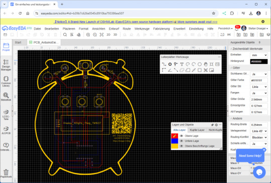
Das Hintergrundbild also quasi den "Wecker" habe ich mir recht günstig bei Etsy.com gekauft und somit sogar noch einen anderen Creator mit diesem Projekt unterstützt ;).
Ausblick
Als nächstes möchte ich dieses Projekt, wie bereits erwähnt, für das Jugendfreizeitzentrum Schöningen umsetzen. Besonders spannend daran ist, dass die Teilnehmer nicht nur das Löten auf einer Platine erlernen, sondern auch erste Erfahrungen im Programmieren sammeln können. Zudem lässt sich der Code erweitern, um beispielsweise die aktuelle Uhrzeit aus dem Internet über einen NTP-Server auf der Segmentanzeige darzustellen. Der ESP32-C3 Mini eröffnet dabei viele weitere Möglichkeiten für kreative Erweiterungen. Read the full article
0 notes
Text
Price: [price_with_discount] (as of [price_update_date] - Details) [ad_1] The PIR Motion Sensor Detector Module HC SR501 allows you to sense motion. It is almost always used to detect the motion of a human body within the sensor’s range. It is often referred to using “PIR”, “Pyroelectric”, “Passive Infrared” and “IR Motion” sensor. The module has an onboard pyroelectric sensor, conditioning circuitry, and a dome-shaped Fresnel lens. It has a delay time adjustment Potentiometer and sensitivity adjustment Potentiometer. Compatible with All type of development board It can automatically and quickly open various types of incandescent, fluorescent lamps, buzzer, automatic doors, electric fans,automatic washing machine and dryer Machines and other devices,is a hightech products. Especially suitable for enterprises, hotels, shopping malls, warehouses and family aisles, corridors and other sensitive Sense of region, or for the security zone automatic lighting, lighting and alarm systems. Infrared Sensor with Control Circuit Board Blockade time: 2.5s (Default) The Sensitivity and Holding Time is adjustable. Blockade time: 2.5s (Default) The module has 3.3v Logic level output and can be used directly MCU development boards and robotics projects. [ad_2]
0 notes
Text
Arduino Projects
Arduino is a microcontroller platform made to facilitate hardware integration and programming. Each of its boards, including the Arduino Uno, Nano, and Mega, is designed to meet a distinct set of requirements. When used in conjunction with the Arduino IDE, users may easily write, upload, and execute code.
Users can design projects ranging from basic LED blinkers to intricate robotics and Internet of Things systems thanks to the platform's extensive library of sensors, modules, and components.
Top Arduino Project Ideas
System for Home Automation
An Arduino with a smartphone app can be used to control lights, fans, and other appliances. Your system can become more intelligent and energy-efficient by integrating sensors like temperature or motion detectors.
The weather station
Construct a personal weather station to track air pressure, temperature, and humidity. You can gather data using sensors like the DHT11 and BMP180, show it on an LCD screen, or post it online for remote access.
Robot That Avoids Obstacles
This well-liked project for robotics novices is teaching a robot to use ultrasonic sensors to navigate around obstacles.
Intelligent Plant Monitoring System
An Arduino-based monitoring system that measures temperature, light intensity, and soil moisture can help you keep your plants healthy. Even when it's time to water your plants, it may let you know.
Alarm System with Arduino
Create an Arduino-powered alarm system with a buzzer, keypad, and motion sensors to increase security. For workplace or home security, this project is perfect.
Pet Feeder with Automation
Construct a pet feeder that automatically delivers food depending on a weight sensor reading or at predetermined intervals.
Internet of Things Door Lock
Create a smart door lock that you can operate from a distance using Bluetooth or Wi-Fi by integrating an Arduino with an RFID scanner or fingerprint sensor.
Make Your Own Game Console
Convert an Arduino board with basic buttons and a display into a vintage game console.
How to Get Started with Arduino Projects
Select the appropriate board:
Choose an Arduino board based on the needs of your project. The Arduino Uno is an excellent place to start for the majority of novices.
Assemble the parts:
Determine the sensors, actuators, and other parts your project needs. A wide range of Arduino-compatible components are available on websites like Adafruit, SparkFun, and Amazon.
Set up the Arduino IDE:
Install the Arduino IDE by downloading it from Arduino.cc. You can develop code and upload it to your board using this software.
The universe of creativity and invention is unlocked by Arduino projects. Arduino offers the resources and network to realize your ideas, whether you want to study robotics, automate your house, or develop a ground-breaking technology.
Explore the world of Arduino now and unleash your creative side! Do you have a favorite idea for an Arduino project? Tell us about it in the comments section below.
To know more, click here.
0 notes
Text
UHF Reader Based on Pico W & ESP32 with 50 Tags/Second Reading within 1.5 Meter Range

A UHF Reader (Ultra High Frequency Reader) is a device that is used to read and write data from UHF RFID tags within the 860MHz-960MHz frequency range. It is a multi tags 50 tags/second reading/writing device within 1-1.5 meter range designed with cutting edge UHF technology. It is a compact, portable and easy to use device.
The UHF reader has 2 variants: one is UHF Reader by Pico W and another is UHF Reader by ESP32. The Pico W variant comes with RP2040 microcontroller with Wi-Fi and BLE support. It is compatible with MicroPython, CircuitPython and Arduino for programming. ESP32 variant comes with ESP32 S3 series microcontroller and has 2.4GHz & Bluetooth 5 (LE) support. It is compatible with Arduino and Espressif IDE for programming.
Key Features and Specifications:
UHF Reader Pico Variant:

Powered by Raspberry Pi Pico W
RP2040 microcontroller dual-core Arm Cortex M0+ microprocessor with 264kB RAM
Supports Wi-Fi and BLE
1.14” TFT display for better visualization
Multi-tone buzzer for audio alerts
Micro USB Support for programming & Type C support for power
3 programmable buttons and Reset button
SD card slot for data storage/transfer
LED Status for power and battery charging
Multipurpose GPIOs breakout for interfacing external peripherals
SWD pins breakout for serial debugging
Supports MicroPython, CircuitPython, and Arduino for programming
UHF Reader ESP32 Variant:

Powered by ESP32 S3 WROOM-1
Dual-core 32 bit LX7 microprocessor with Up to 8 MB PSRAM and up to 16 MB flash memory
Supports 2.4GHz (802.11b/g/n) Wi-Fi and Bluetooth 5 (LE)
1.14” TFT display with ST7789 display driver
Comes with a Read and Write UHF module.
Frequency range of 865.1MHz-867.9MHz (for EU/UK) and 902.25MHz-927.75MHz (for US)
Can Identify 50 tags/second up to the 1.5-meter range.
TTL UART communication interface and communication baud rates 115200bps-38400bps
output power 18-26dBm and output power accuracy +/- 1dB
operation current 180mA at 3.5V (26 dBm Output), 110mA at 3.5V (18 dBm Output)
Multi-tone buzzer for audio alerts
2 user programmable buttons, Boot and Reset buttons
For power and programming support, the Type C Interface
SD Card slot for data transfer/storage
LED status for power and charging
Multipurpose GPIOs breakout for interfacing external peripherals
Supports Arduino and Espressif IDE for programming
By using ESP32 and RP2040, you can build a UHF RFID reader for scan tags and data tracking. This UHF Reader with ESP32 and Pico by SB Components is suitable for applications like warehouses, retail stores, and many other applications where you want to track your inventory data accurately.
#technology#innovation#tech#iot#rfid#uhf#uhf reader#arduino#espressif#iot applications#raspberry pi#rp2040#esp32#projects#programming#ultra high frequency reader#rfid tags#data tracking#electronics
1 note
·
View note
Text
Esplora Arduino game controller

The ESPLORA Arduino game controller Board is an Arduino-compatible microcontroller board based on the Arduino Leonardo. Unlike previous models, it comes equipped with a variety of built-in sensors for immediate use in interactions.
This guide is perfect for individuals interested in using Arduino, but who don’t want to dive into electronics right away. To learn how to use the ESPLORA Arduino game controller Board in a simple and clear manner, be sure to read the Getting Started with Esplora guide.
The ESPLORA Arduino game controller Board boasts onboard sound and light outputs, as well as multiple input sensors such as a joystick, slider, temperature sensor, accelerometer, microphone, and light sensor. Additionally, it offers the option to enhance its functions through two Tinker-kit input and output connectors and a socket for a color TFT LCD screen.
Similar to the Leonardo board, the ESPLORA Arduino game controller Board also utilizes an Atmega32U4 AVR microcontroller with a 16 MHz crystal oscillator. It features a micro USB connection that can function as a USB client device, such as a mouse or keyboard. Additionally, there is a reset push button located in the upper left corner of the board for restarting purposes.
There exist four indicators, each displaying a different status.
The green indicator shows if the board is currently being powered.
The L [yellow] connects directly to pin 13 on the micro-controller for easy accessibility.
The [yellow] LED indicates data being transmitted or received through the USB connection.
Within the board lies all the necessary components to support the microcontroller. To begin, just connect it to a computer using a USB cable. The ESPLORA Arduino game controller Board is also equipped with built-in USB communication, allowing it to function as a mouse or keyboard when connected to a computer. It also offers a virtual serial/COM port (CDC). This alters the behavior of the board, which is further explained on our getting started page. On this page, you can find all the instructions for configuring your board and utilizing the Arduino Software (IDE) for coding and electronics experimentation.
The transfer of data, both in and out.
The ESPLORA Arduino game controller Board features a classic gamepad design, including an analog joystick on the left and four push buttons on the right. It also comes equipped with several onboard inputs and outputs:
The analog joystick features a center push-button and two axes, designated as X and Y. There is also a central pushbutton for added functionality.
Arranged in a diamond formation are 4 push-buttons.
The slider for the linear potentiometer is located towards the bottom of the board.
A tool to capture the volume (amplitude) of the surrounding environment.
A sensor that detects light to measure brightness.
The temperature sensor measures the surrounding temperature.
A three-axis accelerometer detects the orientation of the board with respect to gravity, along the X, Y, and Z axes.
The buzzer has the ability to generate square-wave tones.
The RGB LED features Red, Green, and Blue elements that allow for color mixing and a bright display.
The TinkerKit Inputs allow for easy connection between the sensor modules and 3-pin connectors.
The TinkerKit Outputs allow for easy connection of the TinkerKit actuator modules via the 3-pin connectors.
The TFT display connector can be used for a color LCD screen, SD card, or any other devices utilizing the SPI protocol.
To fully utilize all available sensors, the board employs an analog multiplexer. This way, multiple input channels (excluding the 3-axis accelerometer) can share a single analog input of the microcontroller. Selecting which channel to read is done through four additional pins on the microcontroller.
Communication is essential in any relationship, whether it be personal or professional. It plays a crucial role in maintaining strong connections and fostering understanding between individuals. Effective communication allows for open and honest dialogue, facilitating problem-solving and building trust. Without good communication, misunderstandings can occur, leading to conflicts and strained relationships. Therefore, it is important to prioritize effective communication in every aspect of our lives.
The ESPLORA Arduino game controller Board for the Leonardo offers various features for connecting with a computer, another Arduino, or different micro-controllers. The ATmega32U4 enables serial (CDC) communication through USB and is recognized as a virtual com port on the computer. It also functions as a full speed USB 2.0 device and can be used with standard USB COM drivers. A .inf file is needed for Windows.
The Arduino software comes equipped with a serial monitor for easy transmission of text data to and from the board. Whenever data is being sent via the USB connection to the computer, the RX and TX LEDs will light up on the board. Additionally, the ATmega32U4 has SPI capability accessible through the SPI library. In addition, the Esplora can act as a standard keyboard and mouse, allowing you to use programming to manage these input devices via the Keyboard and Mouse libraries.
The act of creating computer software, also known as programming, involves writing code using various languages and tools. This process requires a combination of problem-solving skills, critical thinking and creativity. Programmers must constantly learn new techniques and adapt to ever-changing technology in order to produce high-quality programs.
To start using the Esplora with your Arduino software (download), simply choose “Esplora” from the Tools > Board menu. For more information, refer to the getting started page. The ATmega32U4 on the Esplora comes pre-loaded with a boot-loader, enabling you to upload new code without an external hardware programmer.
The AVR109 protocol is the chosen method of communication. To avoid using the bootloader, you can program the microcontroller through the ICSP header. Additional instructions are available for reference.
A dedicated library for the Esplora simplifies writing sketches, with methods available for reading sensors and controlling onboard outputs. These high-level methods also perform pre-processing of data, such as converting temperature readings to degrees Fahrenheit or Celsius. Additionally, the library allows easy access to outputs like the RGB LED. For further information and examples, please refer to the Esplora library reference page.
The automatic reset and bootloader activation are key components in the software’s functioning.
Rather than relying on the physical reset button, the Esplora utilizes a software-based reset triggered by opening and then closing the virtual serial/COM port (CDC) at 1200 baud. This initiates a processor reset, temporarily cutting off the USB connection to the computer and causing the virtual port to disappear. The boot-loader remains active for approximately 8 seconds before it can also be activated by pressing the reset button on the Esplora.
Please be aware that upon initial power up, the board will launch the user sketch instead of the boot-loader, if available. Due to the specific reset process of the Esplora, it is most effective to allow the Arduino software to attempt a reset before uploading, especially if you typically press the reset button before uploading on other boards. However, in the event that the software is unable to reset the board, you can manually initiate the boot-loader by pressing the reset button on the board.
The USB port is equipped with overcurrent protection to prevent any potential damage.
The ESPLORA Arduino game controller Board comes equipped with a re-settable poly-fuse to safeguard your computer’s USB ports against shorts and over-current. While most computers have built-in protection, the fuse adds an additional level of security. In the case of a short or overload exceeding 500 mA, the fuse will disconnect the connection until the issue is resolved.
Regarding the appearance of this object, its external features will be discussed.
The ESPLORA Arduino game controller Board PCB has a maximum size of 6.5 inches in length and 2.4 inches in width. The USB and TinkerKit connectors extend beyond the width dimension. Additionally, there are four screw holes that allow for attachment to a surface or case.
1 note
·
View note
Text
Hmm...well something's clearly gone wrong, but I can't work out what
Warning: Volume
I disabled all the software's modules, run the program and the buzzer still screams at me. Thinking I might have some power issue? But haven't been able to spot any shorts or anything
1 note
·
View note
Text

ARM Embedded Computer for Building Security and Surveillance Systems
ote viewing.
Access Control:
Hardware: X-board (RS485/RS232) connects RFID readers, Y-board (DI/DO) controls locks; Ethernet/4G for networking.
Software: BLIIoTLink integrates Modbus/MQTT, Node-RED for access logic.
Application: Face/card-based door access, events uploaded to property management platform.
Intrusion Detection:
Hardware: Y-board connects PIR/vibration sensors; NPU analyzes anomalies.
Software: Node-RED processes sensor data, MQTT uploads to cloud.
Application: Detects unauthorized entry, reduces false alarms with video integration.
Alarm Function:
Hardware: Y-board (relay/PWM) controls buzzers/lights; 4G for notifications.
Software: BLIIoTLink sends alarms to SCADA, BLRAT for remote management.
Application: Triggers sound/light alarms on anomalies, notifies security personnel.
3. Recommended Configuration
Model: BL372B-SOM372-X23-Y24-Y11
3x Ethernet, 32GB eMMC, 4GB RAM, 4x RS485, 4x DI/DO, 4x relays, 8x DI.
4G/WiFi module, Ubuntu 20.04, BLIIoTLink + Node-RED.
Reason: Meets multi-channel video, access control, sensor integration, and cloud communication needs.
4. Advantages
High Performance: NPU + 2.0GHz CPU supports AI and video processing.
Flexibility: Modular I/O adapts to various devices.
Industrial-Grade: Wide temperature range, anti-interference, suitable for building environments.
Easy Development: Node-RED, Qt, BLRAT simplify development and maintenance.
5. Challenges and Solutions
Limited Processing Power: Optimize AI models or add external accelerators.
Network Disruption: Local caching + resumable transmission.
Security: TLS encryption + watchdog protection.
6. Summary
The BL370 efficiently implements video surveillance, access control, intrusion detection, and alarm functions for building security with high-performance hardware and flexible software, suitable for commercial, residential, and industrial scenarios. The recommended BL372B configuration supports rapid deployment and cloud management.
0 notes