#esp32 tutorials
Explore tagged Tumblr posts
Visit Tumblr Blog
Explore Tumblr blogs with no restrictions, modern design and the best experience.
Last Seen Tumblr Blogs


Fun Fact
Tumblr was attacked by a cross-site scripting worm deployed by the Internet troll group GNAA on Dec 3, 2012.
Text
youtube
Simple beginners guide how to build create WebHID API Electron JS Desktop App for windows 10 & windows 11. Electron webhid api Desktop App html js Script: https://bit.ly/4egIyAw or https://drive.google.com/file/d/1euT1JxtpOgdZwVpA5C1nXOZRZ7bnbsoa/ Electron JS Desktop App Project Tutorial for Beginners: WebHID API Example w/ Source Code
#tutorials#how to#programming#arduino#esp32-s2#esp32#WebHID API#Desktop App#Electron#Electron JS#Source Code#Project Tutorial for Beginners#windows 10#windows 11#Youtube
0 notes
Text
Automação da Criptografia e de eFuses no ESP32
Automação da Criptografia e de eFuses no ESP32 é essencial para proteger protótipos e produtos contra violações de propriedade intelectual. Este guia ensina como automatizar o processo, tornando o desenvolvimento mais seguro e eficiente.
A Automação da Criptografia e de eFuses no ESP32 é essencial para quem faz protótipos e até produtos, pois disponibilizar soluções que usam ESP32 sem criptografia é um grande risco para a propriedade intelectual. 1. Explicando a estrutura e como será a automação Antes de mais nada é importante entender que as automações feitas aqui são baseadas na proteção contra leitura e gravação do ESP32 e a…
#Automação criptografia ESP32#Automação ESP32 com Python#Configuração eFuses ESP32#Criptografia binários ESP32#ESP-IDF no Raspberry Pi#ESP32 proteção propriedade intelectual#ESP32S3 segurança#Espefuse.py ESP32S3#Espsecure ESP32 tutorial#Espsecure.py exemplos#Gravação chave AES ESP32#Gravação criptografada ESP32#Gravação de firmware ESP32#Proteção eFuses ESP32#Segurança de firmware ESP32
0 notes
Text
The first test for our WLED board codename "Sparkle Motion" 🌈💖💡 … 🐇⏳🌌
We got our WLED-friend PCBs today, and we only made one mistake: the wrong resistor on the 3.3V feedback line. Now that it's fixed, the board seems to work great with the latest version of WLED
We are checking all 4 signal outputs with this handy 256-LED grid that sits on our desk. Next, we will test the onboard IR receiver, USB PD, I2S microphone, extra I/O pins, and I2C. We'll also do an Arduino IDE board definition in case folks want to use it as a generic ESP32-to-LED-driver board. We're calling the board "Sparkle Motion" for now, but if you have other naming ideas, let us know - if we pick your name, you get a free board
Sign up, coming soon.
#wled#sparklemotion#leddriver#esp32#electronics#pcbs#arduino#makerprojects#openhardware#opensource#coding#leds#hardwaredesign#innovation#techgeeks#smartlighting#microcontrollers#hardwareengineering#esp32projects#ledmatrix#diyhardware#iotprojects#arduinoide#hardwaretesting#ledtechnology#techmakers#electronicscommunity#prototyping#hardwarehacking#adventuresintech
17 notes
·
View notes
Link
2 notes
·
View notes
Text
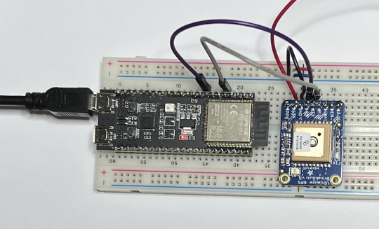
DIY: Marauder with Screen and GPS For Flipper Zero
Many of you would have seen the humongous ESP32 add-on module with touch screen and GPS for Flipper Zero shared in discussion groups, forums, etc. Well, this tutorial will provide you with all the information you need to build one yourself.
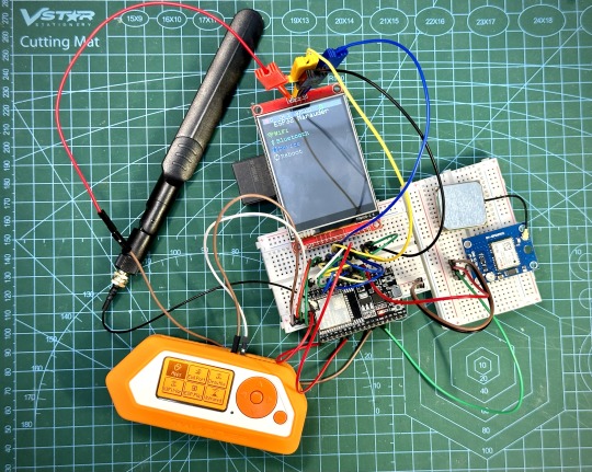
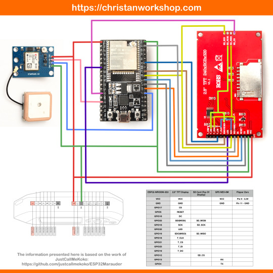
This build consists of mainly 4 parts. The TFT LCD 2.8" 240x320 SPI ILI9341 Touch Display cost me around US$5.50, the ESP32-WROOM-32U module cost around US$3, the NEO-6M GPS module cost around US$2.20 and an 8dbi 2.4GHz Wifi Antenna which cost around US$2. All of these parts can be easily found in online marketplaces like Aliexpress, Amazon, etc. Here is how you need to wire them up together. How you wish to lay this out or mount on a prototyping board is entirely up to you. As long as the connections are correct, you are good to go. The GPS module is optional, and mainly, it's used for the war driving functionality.
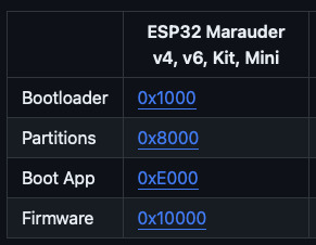
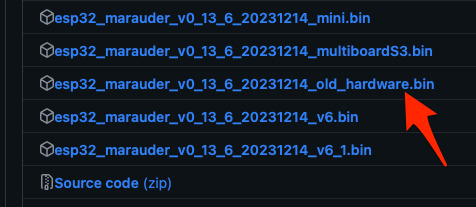
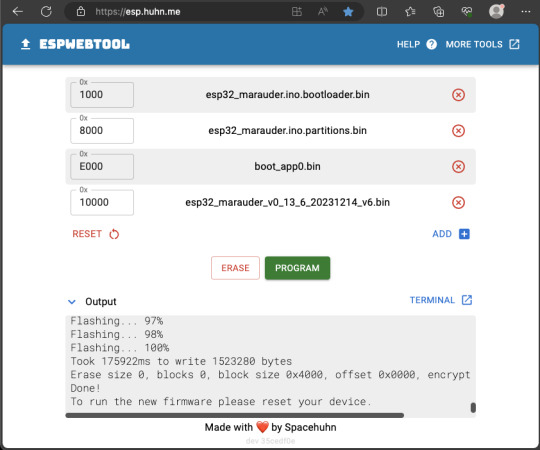
Next, you need to download all the firmware needed from here. Please download the Bootloader, Partitions, Boot App and Firmware files for v4 (Yes, v4 files, not any others) and save it on your computer.
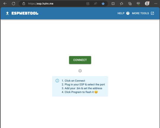
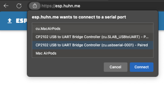
Now, press and hold the BOOT button on your ESP32-WROOM-32U module and connect it to your computer using a data-capable USB cable (some USB cables can only charge), then let go the BOOT button. Open Google Chrome or Microsoft Edge browser and go to ESPWebTool. Click the CONNECT button, then select the ESP32 usb serial connection. It should look something like below but can vary a little between different computers and operating systems.
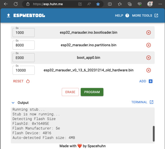
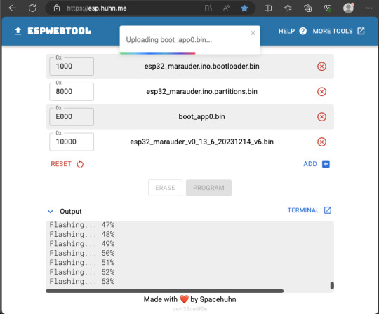
Select the firmware files for each slot exactly like below (take note of the 0x1000, 0x8000, etc. and their corresponding .bin files), then hit the PROGRAM button.
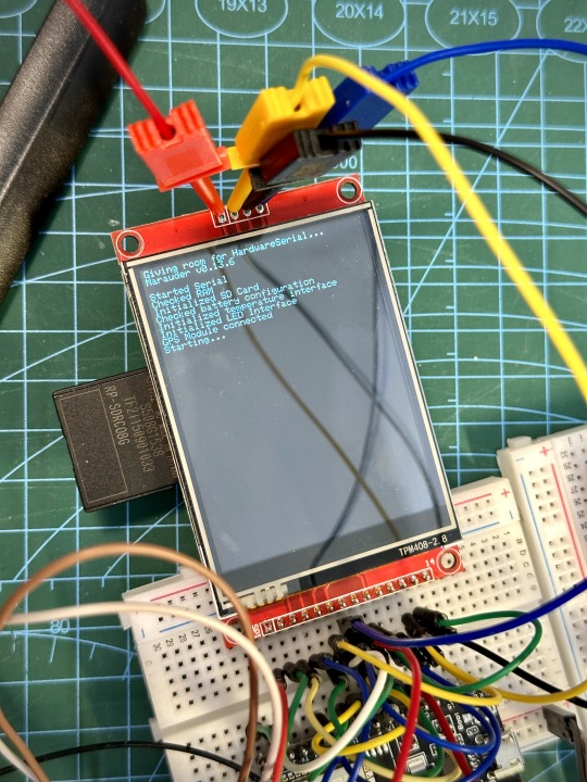
When completed successfully, you can unplug the USB cable from the ESP32 module and now you can connect your Marauder module to your Flipper Zero. Please ensure that your Flipper Zero is turned off before you connect it, and also turn off your Flipper Zero before disconnecting it. The 3.3V pin is also used by your Flipper Zero's SD card reader and connecting/disconnecting external modules that use this pin while the Flipper Zero is on can potentially corrupt the SD card. So, if everything went according to plan, your Marauder module should boot up and everything should look like below.
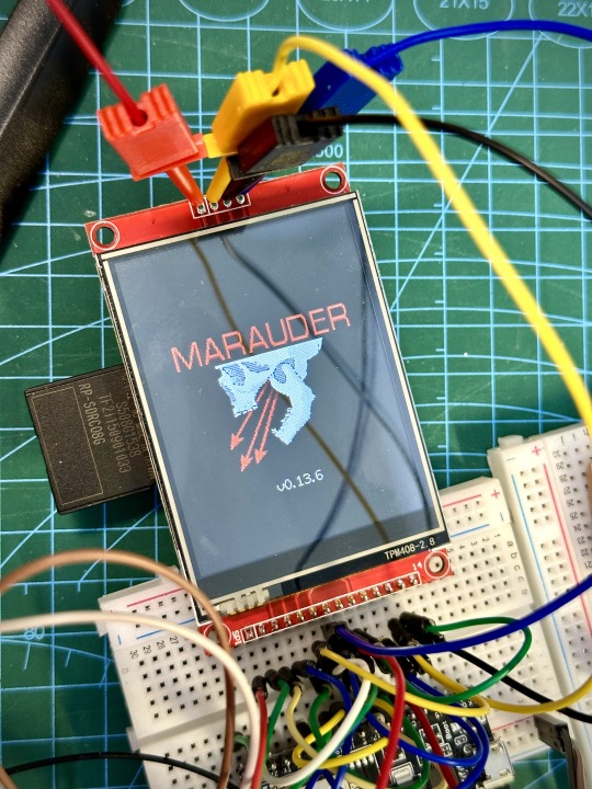
NOTE: If your Marauder boots up, but when you try to touch the screen and get no response, try tapping around the bottom part of your screen and see if the touch panel seems to be in inverted position from the actual display. Should this happen to you, just flash your ESP32 module again following the steps above, but use the v6 firmware. This should resolve the issue.
In this build, I just prototyped this on breadboard, but you can of course make it permanent by soldering it on to a prototype board and 3D print a case for it. This setup is essentially just using the Flipper Zero as a battery pack, instead of using the Flipper Zero to control Marauder. The large screen does make some things easier to do, compared to the small screen of the Flipper Zero, and there may be some functionality (not much) that is not currently in the Flipper Zero Marauder companion app. Here is a video showing the different menus in Marauder.
Personally, I don't think I will actually want to bring something so big around with me, along with my Flipper Zero. I think what makes Flipper Zero special is just how compact it is and all the different functionality cramped into it. This would probably be better off as a standalone unit by just hooking up a battery, but that's just me. Well, that's it for this tutorial. I hope you found this helpful.
Here's a good intro to Marauder if you are unfamiliar.
youtube
18 notes
·
View notes
Text
A very simple tutorial; like 5 minutes of soldering. The default tutorial sends the data to Adafruit's logging platform, but I'm sure it's possible to set it up to log AQI readings to your own Grafana server or something like that.

Air quality!
4 notes
·
View notes
Text

SunFounder ESP32 Ultimate Starter Kit – All-in-One IoT Learning Platform for Every Level
Discover the SunFounder ESP32 Ultimate Starter Kit – perfect for beginners and pros. Learn IoT, home automation, Bluetooth, and camera projects with 50+ tutorials and multi-language coding support.
1 note
·
View note
Text
Smarthome ohne Spionage: ESP32 und Shelly i4 DC als drahtlose Steuerung für dein Zuhause
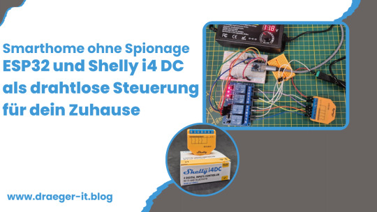
Ich möchte dir eine drahtlose Steuerung mit ESP32 und einem Shelly i4 DC vorstellen, mit der du Smart-Home-Geräte komfortabel bedienen kannst. Viele setzen dabei auf Sprachassistenten wie Alexa oder Google Assistant – doch nicht jeder möchte sich einen „Spion“ ins Haus holen, der dauerhaft zuhört. Eine Funksteuerung mit ESP32 und Shelly i4 DC ist eine sichere, lokale und flexible Alternative, die ohne Cloud oder Internet funktioniert. https://youtu.be/oVJkW2YQ7To Den Shelly i4 DC habe ich bereits ausführlich in meinem Beitrag "Smarter Schalter für Gleichspannung: Der Shelly i4 DC im Detail" vorgestellt. Zudem findest du auf meinem Blog bereits zahlreiche Beiträge zum ESP32, da dieser Mikrocontroller eine perfekte Grundlage für smarte DIY-Projekte bietet. Mit einer 4-Tasten-Funkfernbedienung und dem Shelly i4 DC lassen sich bis zu vier verschiedene Aktionen ausführen – von der Lichtsteuerung bis zum Öffnen des Garagentors. In diesem Beitrag zeige ich dir, wie du diese praktische und datenschutzfreundliche Smart-Home-Lösung umsetzt.

Schaltung - Shelly i4 DC mit Relais Modul und ESP32-S3-Zero
Warum diese Schaltung, wenn Shelly auch per WebHook steuerbar ist?
Theoretisch kann man jeden Shelly direkt über WebHooks steuern, indem man HTTP-Requests an das Gerät sendet. Damit ließen sich Shelly-Produkte ganz ohne zusätzliche Hardware per WLAN in ein Smart-Home-System einbinden. Aber: Was, wenn du eine unabhängige, einfache Lösung suchst? Ich möchte dir hier eine alternative Schaltung zeigen, mit der du Geräte in deinem Smart Home über eine klassische Funkfernbedienung (433 MHz) bedienen kannst – ohne WLAN, Cloud oder App. Diese Lösung ist besonders dann interessant, wenn du: ✔ Geräte lokal und offline steuern möchtest, ohne auf eine Internetverbindung angewiesen zu sein. ✔ Eine einfache Fernsteuerung bevorzugst, die keine App oder komplizierte Einrichtung erfordert. ✔ Ein bestehendes Funk-Setup mit 433 MHz Fernbedienungen nutzt und dieses mit Shelly kombinieren möchtest. Dazu setze ich einen ESP32 mit einem 433 MHz Funkempfänger und einem 4-fach Relais-Modul ein. Die Relais steuern die Eingänge des Shelly i4 DC, sodass du mit einer drahtlosen 4-Tasten-Fernbedienung bis zu vier verschiedene Smart-Home-Aktionen auslösen kannst.
Die richtige Funkfernbedienung wählen
Wer eine passende 4-Tasten-Funkfernbedienung sucht, findet auf AliExpress und eBay eine große Auswahl an Modellen. Wichtig ist, auf die Frequenz zu achten: In Deutschland sind 433 MHz-Modelle erlaubt und weit verbreitet, während 333 MHz-Fernbedienungen hier nicht genutzt werden dürfen. Dies ergibt sich aus dem Frequenzplan der Bundesnetzagentur, der die zulässigen Funkfrequenzen regelt. Achte daher beim Kauf darauf, dass das gewählte Modell den gesetzlichen Vorgaben entspricht. Das 433 MHz Funksender Kit für den Arduino habe ich dir bereits im Beitrag Arduino Tutorial 37: 433 MHz Sender & Empfänger
Benötigte Hardware für das Projekt
Für dieses Projekt kommen folgende Hardware-Komponenten zum Einsatz: - ESP32-S3 Super Mini von Waveshare* – ein leistungsstarker Mikrocontroller mit WLAN- und Bluetooth-Funktionalität - Shelly i4 DC* – ein smarter Schalter mit vier digitalen Eingängen für Gleichspannung - 433 MHz Funkempfänger* – zur drahtlosen Signalübertragung von der Fernbedienung an den ESP32 - 433 MHz Funksender* – ermöglicht das Senden von Signalen an andere Geräte (günstig im 2er-Set erhältlich) - vierfach-Relais-Modul* – dient zur galvanischen Trennung und ermöglicht das Schalten der Eingänge am Shelly i4 DC - diverse Breadboardkabel & 400-Pin Breadboard* – für eine einfache Verdrahtung ohne Löten - ein USB-Netzteil* - wird für die Stromversorgung des Mikrocontrollers und des Shellys benötigt - ein Power-Supply-Modul für Breadboard* - über dieses Modul kann man 5V & 3.3V abgreifen um unter anderem den Shelly zu betreiben Hinweis von mir: Die mit einem Sternchen (*) markierten Links sind Affiliate-Links. Wenn du über diese Links einkaufst, erhalte ich eine kleine Provision, die dazu beiträgt, diesen Blog zu unterstützen. Der Preis für dich bleibt dabei unverändert. Vielen Dank für deine Unterstützung! Stromversorgung Sowohl der ESP32-S3 Super Mini als auch der Shelly i4 DC benötigen eine Stromquelle. Hier eignet sich theoretisch ein einfaches USB-Netzteil*, das sich leicht zweckentfremden lässt. Da der Shelly i4 DC bereits ab 5V betrieben werden kann und weniger als 1W Leistungsaufnahme hat, reicht ein handelsübliches Netzteil vollkommen aus.
Aufbau der Schaltung - Shelly i4 DC via Funkfernbedienung über ESP32 steuern
Nachfolgend die kleine Schaltung im Schaubild wie die Komponenten zusammenarbeiten.
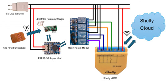
Schaltung - 433MHz Remotecontroll und Shelly i4 DC KomponenteESP32-S3 Mini4fach Relais ModulVCC5VGNDGNDIN1GP2IN2GP3IN3GP4IN4GP5433 MHz FunkempfängerVCC5VGNDGNDDATAGP1 Anschlussklemme des Relais Ein 4-fach Relaismodul bietet für jeden Kanal eine dreipolige Anschlussklemme, bestehend aus: - Links (NC - Normally Closed) → Ausgang aktiv, wenn die Relais-LED AUS ist - Mitte (COM - Common) → Gemeinsamer Anschluss für den Schaltkreis - Rechts (NO - Normally Open) → Ausgang aktiv, wenn die Relais-LED AN ist
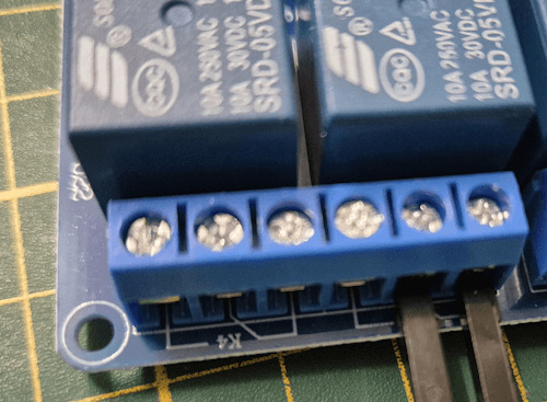
Relais Modul-Anschlussklemme Verdrahtung mit dem Shelly i4 DC - Der GND-Anschluss des Shelly i4 DC wird mit dem rechten (GND) Anschluss der Relaisklemme verbunden. - Die Eingänge des Shelly i4 DC können entweder über den mittleren (NO) oder linken (NC) Kontakt mit dem Relais verbunden werden, je nach gewünschtem Schaltverhalten: - NO (Normally Open): Eingang wird aktiv, wenn das Relais anzieht (LED leuchtet). - NC (Normally Closed): Eingang wird aktiv, wenn das Relais nicht angezogen ist (LED aus). Pinout des ESP32-S3 Mini Nachfolgend das Pinout des ESP32-S3-Zero von Waveshare.

Aufbau - ESP32-S3-Zero
Programmieren - drahtlose Steuerung eines Shelly i4 DC am ESP32
fertiges Programm Programm: drahtlose Steuerung eines Shelly i4 DC über ESP32Herunterladen Quellcode /* Projekt: Smarthome ohne Spionage – Funksteuerung für den Shelly i4 DC mit ESP32 Autor: Stefan Draeger Blog: https://draeger-it.blog Beitrag: https://draeger-it.blog/smarthome-ohne-spionage-esp32-und-shelly-i4-dc-als-drahtlose-steuerung-fuer-dein-zuhause/ Beschreibung: Dieser Code ermöglicht es, einen Shelly i4 DC über ein 4-fach Relais-Modul zu steuern. Die Relais werden mit einem 433 MHz Funkempfänger in Kombination mit einem Handsender geschaltet. Der ESP32 empfängt die Funksignale und schaltet entsprechend die Relais, welche die Eingänge des Shelly i4 DC bedienen. Benötigte Hardware: - ESP32 (z. B. ESP32-S3 Super Mini) - 433 MHz Funkempfänger - 433 MHz Funksender - 4-fach Relais-Modul - Shelly i4 DC - Passende Netzteile für ESP32 und Shelly Hinweis: Der Code nutzt die RCSwitch-Bibliothek, um die 433 MHz Funksignale zu dekodieren. */ #include // Initialisierung des RCSwitch-Objekts zur Kommunikation mit dem 433 MHz Empfänger RCSwitch rcSwitch = RCSwitch(); // Definition der GPIO-Pins #define remotePin 1 // Empfangs-Pin für den 433 MHz Empfänger #define relais1 2 // Steuerpin für Relais 1 #define relais2 3 // Steuerpin für Relais 2 #define relais3 4 // Steuerpin für Relais 3 #define relais4 5 // Steuerpin für Relais 4 // Definition von Zuständen für die Relaissteuerung #define AN true // Relais einschalten #define AUS false // Relais ausschalten // Codes für die 433 MHz Funkfernbedienung (Ein- und Ausschalten der Relais) const long TASTE_1_ON = 83029; const long TASTE_1_OFF = 83028; const long TASTE_2_ON = 86101; const long TASTE_2_OFF = 86100; const long TASTE_3_ON = 70741; const long TASTE_3_OFF = 70740; const long TASTE_4_ON = 21589; const long TASTE_4_OFF = 21588; void setup() { Serial.begin(9600); // Serielle Kommunikation starten rcSwitch.enableReceive(remotePin); // Aktivierung des 433 MHz Empfängers auf remotePin // Setzen der Relais-Pins als Ausgang pinMode(relais1, OUTPUT); pinMode(relais2, OUTPUT); pinMode(relais3, OUTPUT); pinMode(relais4, OUTPUT); // Alle Relais beim Start ausschalten digitalWrite(relais1, AUS); digitalWrite(relais2, AUS); digitalWrite(relais3, AUS); digitalWrite(relais4, AUS); } void loop() { // Prüfen, ob ein Signal vom 433 MHz Handsender empfangen wurde if (rcSwitch.available()) { long remoteValue = rcSwitch.getReceivedValue(); // Empfangenen Code auslesen rcSwitch.resetAvailable(); // Empfangsstatus zurücksetzen Serial.println(remoteValue); // Empfangenen Code zur Diagnose ausgeben // Überprüfung, ob der empfangene Code einem gespeicherten Befehl entspricht switch (remoteValue) { case TASTE_1_ON: toggleRelais(relais1, AN); break; case TASTE_1_OFF: toggleRelais(relais1, AUS); break; case TASTE_2_ON: toggleRelais(relais2, AN); break; case TASTE_2_OFF: toggleRelais(relais2, AUS); break; case TASTE_3_ON: toggleRelais(relais3, AN); break; case TASTE_3_OFF: toggleRelais(relais3, AUS); break; case TASTE_4_ON: toggleRelais(relais4, AN); break; case TASTE_4_OFF: toggleRelais(relais4, AUS); break; default: Serial.println("Code : " + String(remoteValue) + " nicht behandelt!"); // Fehlermeldung, falls Code unbekannt } } } // Funktion zur Steuerung eines Relais void toggleRelais(int pin, bool newStatus) { digitalWrite(pin, newStatus); // Setzt das Relais auf AN oder AUS } Auslesen einer Funkfernbedienung Jede Taste an einer Funkfernbedienung hat eine eigene einzigartige ID welche wir zunächst ermitteln müssen. Dazu reicht das kleine Script aus dem bereits veröffentlichten Beitrag Arduino Tutorial 37: 433 MHz Sender & Empfänger. /* Projekt: 433 MHz Signalempfang mit RCSwitch Autor: Stefan Draeger Webseite: https://draeger-it.blog Beschreibung: Dieser Code dient dazu, Signale von einem 433 MHz Funksender zu empfangen und auf der seriellen Schnittstelle auszugeben. Der ESP32 oder Arduino empfängt dabei Funksignale von einer 433 MHz Fernbedienung oder anderen kompatiblen Sendern. Benötigte Hardware: - 433 MHz Funkempfänger - Mikrocontroller (z. B. ESP32 oder Arduino) - Serielle Schnittstelle für die Diagnose */ #include // Einbinden der Bibliothek für die 433 MHz Funkkommunikation // Erstellen eines Objekts für die RCSwitch-Klasse zur Steuerung des Funkempfängers RCSwitch rcSwitch = RCSwitch(); void setup() { Serial.begin(9600); // Start der seriellen Kommunikation mit 9600 Baud // Aktivierung des 433 MHz Empfängers auf Interrupt-Pin 0 (digitaler Pin 2 auf Arduino) rcSwitch.enableReceive(0); } void loop() { // Überprüfung, ob neue Daten vom 433 MHz Sender empfangen wurden if (rcSwitch.available()) { // Ausgabe des aktuellen Zeitstempels (Millisekunden seit dem Start des Mikrocontrollers) Serial.print(" - "); // Ausgabe des empfangenen Codes auf der seriellen Schnittstelle Serial.println(rcSwitch.getReceivedValue()); // Zurücksetzen des Empfängers, damit neue Signale verarbeitet werden können rcSwitch.resetAvailable(); } }
Schritt-für-Schritt-Anleitung
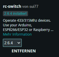
Nachfolgend erläutere ich dir den Aufbau des Quellcodes für eine drahtlose Steuerung des Shelly i4 über einen ESP32. Schritt 1 - einbinden der Bibliothek und definieren der Pins Für den 433 MHz Funkempfänger benötigen wir zusätzlich eine Bibliothek. Hier verwende ich "rc-switch von sui77" welche über den Bibliotheksverwalter installiert werden kann wenn du nach "rc-switch" suchst.
#include // Bibliothek für die 433 MHz Funkkommunikation einbinden // Initialisierung des RCSwitch-Objekts zur Kommunikation mit dem 433 MHz Empfänger RCSwitch rcSwitch = RCSwitch(); // Definition der GPIO-Pins #define remotePin 1 // Empfangs-Pin für den 433 MHz Empfänger #define relais1 2 // Steuerpin für Relais 1 #define relais2 3 // Steuerpin für Relais 2 #define relais3 4 // Steuerpin für Relais 3 #define relais4 5 // Steuerpin für Relais 4 // Definition der Zustände für die Relaissteuerung #define AN true // Relais EIN #define AUS false // Relais AUS Schritt 2 - Konstanten für die Tasten Über das kleine Programm oben habe ich nachfolgende Codes der Tasten ermittelt. Da sich diese Werte nicht ändern habe ich diese in Konstanten abgelegt. // Codes für die 433 MHz Funkfernbedienung (Ein- und Ausschalten der Relais) const long TASTE_1_ON = 83029; const long TASTE_1_OFF = 83028; const long TASTE_2_ON = 86101; const long TASTE_2_OFF = 86100; const long TASTE_3_ON = 70741; const long TASTE_3_OFF = 70740; const long TASTE_4_ON = 21589; const long TASTE_4_OFF = 21588; Schritt 3 - Funktion setup Die Funktion setup wird einmalig aufgerufen wenn der Mikrocontroller startet oder auch neugestartet wird. Hier definieren wir die Pins des Relais Moduls als Ausgang und deaktivieren initial die Relais. void setup() { Serial.begin(9600); // Serielle Kommunikation starten rcSwitch.enableReceive(remotePin); // Aktivierung des 433 MHz Empfängers auf remotePin // Setzen der Relais-Pins als Ausgang pinMode(relais1, OUTPUT); pinMode(relais2, OUTPUT); pinMode(relais3, OUTPUT); pinMode(relais4, OUTPUT); // Alle Relais beim Start ausschalten digitalWrite(relais1, AUS); digitalWrite(relais2, AUS); digitalWrite(relais3, AUS); digitalWrite(relais4, AUS); } Schritt 4 - Funktion loop Die Funktion loop wird dauerhaft ausgeführt bis der Strom abfällt oder ein Fehler auftritt. void loop() { // Prüfen, ob ein Signal vom 433 MHz Handsender empfangen wurde if (rcSwitch.available()) { long remoteValue = rcSwitch.getReceivedValue(); // Empfangenen Code auslesen rcSwitch.resetAvailable(); // Empfangsstatus zurücksetzen Serial.println(remoteValue); // Empfangenen Code zur Diagnose ausgeben //Switch/Case Abfrage } } Schritt 4.1 - Switch / Case für die Tasten Über eine switch Anweisung kann man einfach den empfangenen Wert mit den der Tasten vergleichen. // Überprüfung, ob der empfangene Code einem gespeicherten Befehl entspricht switch (remoteValue) { case TASTE_1_ON: toggleRelais(relais1, AN); break; case TASTE_1_OFF: toggleRelais(relais1, AUS); break; case TASTE_2_ON: toggleRelais(relais2, AN); break; case TASTE_2_OFF: toggleRelais(relais2, AUS); break; case TASTE_3_ON: toggleRelais(relais3, AN); break; case TASTE_3_OFF: toggleRelais(relais3, AUS); break; case TASTE_4_ON: toggleRelais(relais4, AN); break; case TASTE_4_OFF: toggleRelais(relais4, AUS); break; default: Serial.println("Code : " + String(remoteValue) + " nicht behandelt!"); // Fehlermeldung, falls Code unbekannt }
Erweiterte Möglichkeit: Bis zu 8 Geräte mit einem 4-fach Relais steuern
Theoretisch lassen sich mit dieser Schaltung nicht nur vier, sondern bis zu neun verschiedene Geräte steuern – indem man die vier Eingänge des Shelly i4 DC als Bitmuster verwendet.
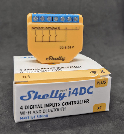
Shelly i4 DC Wie funktioniert das? - Die ersten drei Eingänge (SW1,SW2, SW3) des Shelly i4 DC werden als Binärcode für die Gerätewahl genutzt. - Der vierte Eingang (SW4) wird als Bestätigungssignal (High-Pegel) verwendet, um die Auswahl auszuführen. Bitmuster für die Geräteauswahl SW1SW2SW3Gerät000Gerät 1001Gerät 2010Gerät 3011Gerät 4100Gerät 5101Gerät 6110Gerät 7111Gerät 8xxxKeine Aktion (SW4 nicht aktiviert) Ablauf der Steuerung - Mit der Funkfernbedienung wird ein 3-Bit-Muster auf die Eingänge SW1-SW3 gesetzt (z. B. „101“ für Gerät 6). - Sobald SW4 auf High gesetzt wird, wertet der Shelly das Bitmuster aus und schaltet das zugewiesene Gerät. - Danach werden alle Eingänge zurückgesetzt, um eine neue Auswahl zu ermöglichen. Vorteile dieser Methode ✔ Erweitert die Steuerungsmöglichkeiten erheblich – statt nur 4 sind bis zu 8 Geräte steuerbar. ✔ Nutzt die vorhandenen Relais effizient – kein zusätzliches Hardware-Modul nötig. ✔ Schnelle und flexible Steuerung – einfach per Funkfernbedienung umsetzbar. Diese Methode zeigt, wie viel Potenzial in der Kombination aus ESP32, Shelly i4 DC und einem 4-fach Relais-Modul steckt! 🚀 Read the full article
0 notes
Text
youtube
how to create custom USB HID Device w/ USB HID Vendor Feature report for WEMOS Lolin S2 Mini WebHID API Live Demo Example data exchange (USB Host - USB Client): https://webhidvendor.blogspot.com/ WEMOS Lolin S2 Mini Custom USB HID - WebHID API Live Demo Example Web Interface ESP32 Arduino Core
#WEMOS#programming#how to#arduino#esp32-s2#tutorials#esp32#WebHID API#WebHID API Live Demo#Lolin S2 Mini#Custom USB HID#Vendor Feature report#Youtube
0 notes
Text
Using Rust for Embedded Systems: A Tutorial on the ESP32
Introduction Using Rust for Embedded Systems: A Tutorial on the ESP32 Overview This tutorial will guide you through the process of using Rust for embedded systems development on the ESP32, a popular microcontroller from Espressif. Rust is a systems programming language that offers excellent performance, memory safety, and concurrency features, making it an ideal choice for embedded systems…
0 notes
Link
In this tutorial, we will walk you through the process of displaying your YouTube subscriber count on a MAX7219 8-Digit 7-Segment Display using an ESP32 Node MCU. Whether you’re a YouTuber looking to showcase live stats or an electronics enthusiast diving into IoT projects, this step-by-step guide is for you!
0 notes
Text
ESP32 Cam External Antenna Mod

I am now working on building my own Mayhem board for Flipper Zero, so the first thing was to do some testing with ESP32 Cam module. The range of the internal antenna wasn’t great, so it’s time to hookup an external antenna. Thankfully, the process is well documented by Random Nerd Tutorials.
We will need to desolder a zero ohm resistor and move it to a different position, and resolder it in place, as shown in the image below (taken from the above tutorial).

Here’s a close up of how it looks like on my ESP32 Cam module.


I just used my soldering iron to melt the solder joints and pushed that resistor aside. That resistor is crazy tiny and I had to use a magnifying glass to do this. After removing it, I just applied some flux on the joints for the external antenna and just soldered across them to connect them. You don’t need to use the resistor and trying to solder that back in place was a major pain. I know, I tried … lol
Anyway, my testing shows that using the external antenna, Marauder was able to find 4x more access points than using the internal antenna. Success!
If you wish to learn more about ESP32 Cam, check out this article.
2 notes
·
View notes
Text
How to Learn Embedded Systems: A Comprehensive Guide
Embedded systems are integral to countless applications, from consumer electronics to industrial automation. Understanding how to learn embedded systems can open up a world of opportunities in various fields, including robotics, automotive, healthcare, and IoT. Here’s a structured approach to mastering embedded systems.

1. Understanding the Basics
Start with the fundamentals of embedded systems. Familiarize yourself with key concepts such as:
What are Embedded Systems?
Embedded systems are specialized computing systems that perform dedicated functions within larger mechanical or electrical systems. Unlike general-purpose computers, they are designed to execute specific tasks with high reliability.
Components of Embedded Systems:
Microcontrollers and Microprocessors: Understand the difference between the two. Microcontrollers are compact integrated circuits designed to govern a specific operation in an embedded system, while microprocessors are the central unit of a computer that performs calculations and logic operations.
Memory: Learn about different types of memory (RAM, ROM, Flash) used in embedded systems.
Input/Output Devices: Familiarize yourself with sensors, actuators, and communication interfaces (UART, SPI, I2C).
2. Choose Your Learning Resources
Select resources that match your learning style. Here are some options:
Books:
"Embedded Systems: Introduction to the MSP432 Microcontroller" by Jonathan Valvano
"Programming Embedded Systems in C and C++" by Michael Barr
Online Courses:
Platforms like Coursera, Udemy, and edX offer courses in embedded systems. Look for those that cover microcontrollers, programming, and interfacing.
YouTube Channels:
Channels like "The DIY Life" and "NPTEL" provide practical insights and tutorials on embedded systems.
3. Get Hands-On Experience
Theory is essential, but hands-on practice is crucial for mastering embedded systems. Consider the following:
Development Boards:
Start with popular development boards like Arduino, Raspberry Pi, or ESP32. These platforms are beginner-friendly and have extensive community support.
Build Projects:
Create simple projects like LED blinkers, temperature sensors, or motor controls. Gradually move to more complex projects like home automation systems or robotic applications.
Use Simulation Tools:
Familiarize yourself with simulation tools like Proteus or MATLAB/Simulink for testing your designs virtually.
4. Learn Programming Languages
Embedded systems often require programming skills. Focus on:
C/C++ Programming:
C is the most commonly used language for embedded systems due to its efficiency and control over hardware. Learn the syntax, data structures, and memory management.
Assembly Language:
Understanding assembly language can provide deeper insights into how microcontrollers operate.
5. Explore Real-Time Operating Systems (RTOS)
Many embedded systems require multitasking and real-time performance. Learning about RTOS concepts can be beneficial:
Understand the Basics:
Familiarize yourself with the concepts of task scheduling, inter-task communication, and resource management.
Hands-On with RTOS:
Try using an RTOS like FreeRTOS or Zephyr on your development board. Implement multitasking projects to get practical experience.
6. Join Online Communities
Engaging with fellow learners and professionals can enhance your learning experience:
Forums and Discussion Groups:
Platforms like Stack Overflow, Reddit, and specialized forums (e.g., Embedded Related) are great for seeking help and sharing knowledge.
Attend Workshops and Webinars:
Participate in online workshops or local meetups to learn from experts and network with peers.
7. Stay Updated with Industry Trends
The field of embedded systems is constantly evolving. Keep yourself updated with the latest trends and technologies:
Follow Industry News:
Subscribe to blogs, newsletters, and magazines related to embedded systems.
Participate in Hackathons:
Engage in hackathons or coding competitions focused on embedded systems to test your skills and learn from others.
Conclusion
Learning embedded systems requires a mix of theoretical knowledge and practical experience. By following this structured approach—starting from the basics, choosing the right resources, getting hands-on experience, and staying engaged with the community—you can build a strong foundation in embedded systems. Whether you aim to work in robotics, IoT, or automation, mastering embedded systems can significantly enhance your career prospects. Start your journey today, and embrace the exciting world of embedded systems!
0 notes
Text

Build Your Own Breadboard Phone!
“Have you ever wanted to build your own phone from scratch? Preferably on the most ubiquitous electronics prototyping platform for maximum flexibility and minimum ergonomics? Now you can!”
Maker shop SparkFun has a new tutorial on how to literally build your own cellphone from parts — add a SIM card and you can make phone calls with it. If you’ve ever complained about how today's phones are “boring” or “all look the same”, here’s your chance to do something about it.
(It only makes voice calls, but you could add smartphone features — one of those boards is an ESP32 microcontroller, a reasonably powerful computer with WiFi and Bluetooth that you could plug a touchscreen into for another $20 or so.)
It’s not going to be cheaper than a basic off the shelf phone, though. The cellular module (the skinny board between the rabbit ears and speaker) costs $150, and a bunch of other parts are in the $20 range. And you’ll need a case because this isn’t going to stay together after you’ve pulled it out of your purse or pocket a few times.
1 note
·
View note
Text
ESP32 Serial Ports - UART0, UART1, UART2 Access Using the Arduino IDE
The ESP32 has three UART interfaces: UART0, UART1, and UART2. They provide asynchronous, bidirectional communication at up to five Mbps. You can establish serial protocols using the appropriate breakout boards, such as RS232, RS422, RS485, USB, and more.
1 note
·
View note