#micro linear actuator
Explore tagged Tumblr posts
Visit Tumblr Blog
Explore Tumblr blogs with no restrictions, modern design and the best experience.
Last Seen Tumblr Blogs


Fun Fact
Tumblr has a 66 index score for customer satisfaction in the US.
Text
0 notes
Text
Automated Production and Testing Processes of Rocker Switches

1. Introduction
With the rapid development of industrial automation, the manufacturing process of rocker switches has undergone a transformation from traditional manual production to highly automated, precision-controlled production lines. This shift not only improves production efficiency and product consistency but also enhances the competitiveness of enterprises in the market. This article will provide a comprehensive overview of the automated production and testing processes of rocker switches, including automated terminal insertion, automated spot welding, automated LED placement, as well as contact resistance testing, travel and pressure testing, continuity time measurement, and industrial vision-based appearance inspection. These technologies represent a high degree of integration between mechanical systems, electronic control, and intelligent algorithms.
2. Automated Assembly Processes in Rocker Switch Production
2.1 Automated Terminal Insertion
Terminal insertion is one of the most critical steps in rocker switch production. Traditional manual insertion is prone to positional deviation and insertion force instability, which may cause defective contact or product rejection. Modern production lines adopt servo-controlled automated terminal insertion systems, which use multi-axis manipulators to position terminals precisely. High-precision optical sensors ensure insertion depth and orientation consistency.
For instance, the system automatically picks the copper terminal from the feeder, precisely aligns it with the switch base, and inserts it at a controlled speed and pressure. This ensures the mechanical integrity of the assembly and avoids micro-damage to the plastic shell, laying a solid foundation for subsequent spot welding.
2.2 Automated Spot Welding
Spot welding ensures the electrical connection between terminals and leads. The automated welding station uses resistance spot welding controlled by pulse current and time curves to precisely fuse metal interfaces.
Advanced systems are equipped with closed-loop current monitoring and displacement sensors, allowing real-time compensation for contact surface changes, thus ensuring stable and low-resistance welded joints. Additionally, the system is integrated with fume extraction and safety monitoring modules, improving the working environment and overall safety.
2.3 Automated LED Placement
Rocker switches with indicator lights require precise LED placement. Automated LED placement machines use high-speed pick-and-place heads and machine vision calibration to accurately position the LED within the switch cavity. The polarity and brightness are verified in real time during the process to ensure optical performance and visual consistency.
This process ensures that the LED does not shift during encapsulation or welding, maintaining long-term reliability and aesthetic appeal of the final product.
3. Automated Testing Systems for Rocker Switches
To ensure product reliability, each rocker switch must undergo comprehensive electrical and mechanical performance tests before leaving the factory.
3.1 Contact Resistance Test
The contact resistance test evaluates the resistance value across the conductive path under rated pressure. Modern automated testing equipment uses a 4-wire Kelvin method to eliminate lead resistance influence. The system can test multiple switches simultaneously, display resistance distribution curves in real-time, and automatically classify unqualified products.
Typical requirement: contact resistance < 50 mΩ (depending on the application scenario).
3.2 Travel and Pressure Test
Travel and pressure tests ensure the rocker switch provides the correct tactile feedback. High-precision linear actuators simulate human finger pressing motion, while pressure sensors and displacement encoders collect force-displacement data.
This allows evaluation of stroke range (e.g., 1.8–2.5 mm), actuation force (e.g., 300–600 gf), and pressing smoothness. Abnormalities such as mechanical jamming, misalignment, or inconsistent feedback can be identified and rejected automatically.
3.3 Continuity Time Measurement
Continuity time refers to the response speed of the switch after actuation. The test system uses high-speed data acquisition cards to detect signal transition points and calculate the time difference between actuation and circuit conduction.
This indicator is especially important for automotive and industrial control applications, where millisecond-level response times are required.
4. Visual Inspection and Intelligent Defect Detection
4.1 Industrial Vision System Introduction
Visual inspection replaces traditional manual quality checks, using high-resolution cameras, lighting modules, and image recognition algorithms to inspect every rocker switch.
It can detect:
Missing parts
Scratches or deformation on the housing
Logo misalignment or blurring
Incorrect assembly (e.g., misaligned rockers, LED offset)
4.2 High Efficiency and Accuracy
For example, a dual-camera system combined with a rotary conveyor can inspect 120 pieces per minute. The system achieves a detection accuracy of 0.05 mm, capable of identifying minute cracks or flash edges on plastic parts.
Deep learning algorithms further enhance recognition ability by learning from real production defects, continuously optimizing detection logic.
5. Traceability and Data Integration
All testing data and inspection results are integrated into the MES (Manufacturing Execution System), enabling full traceability. This helps:
Identify root causes of quality issues quickly
Analyze yield trends
Refine production parameters in real time
By applying barcode/QR code identification to each unit, data from insertion, welding, testing, and inspection can be correlated with the specific product batch, greatly enhancing quality control and accountability.
6. Conclusion
The automated production and testing processes of rocker switches represent the future trend of smart manufacturing in the electromechanical components industry. From terminal insertion to visual inspection, each step is carefully controlled and monitored, improving production efficiency, product quality, and cost-effectiveness. With continued development in industrial AI and robotics, the production of rocker switches will become even more intelligent, flexible, and scalable, helping enterprises meet the diverse and demanding needs of global markets.
en.dghongju.com
0 notes
Text
Improving Safety with Linear Technology in Heavy-Duty Manufacturing
The world of heavy-duty manufacturing is undergoing a powerful transformation as precision engineering and robust machinery intersect through advanced linear technology. This shift is redefining how large-scale operations manage tasks that demand both strength and exactitude. In 2025, the integration of linear motion systems is no longer a luxury but a necessity for industries that require both performance and reliability under extreme conditions.
Understanding Linear Technology in Manufacturing Linear technology refers to motion systems that allow controlled linear movement along a straight path. These systems typically include actuators, linear guides, and drive mechanisms designed to enable smooth, precise motion. In manufacturing, especially heavy-duty environments, the demand for precision in large-scale movements is rapidly rising. This is where linear motion components play a transformative role.
Why Heavy-Duty Manufacturing Needs Linear Motion Heavy-duty manufacturing involves tasks such as forging, cutting, molding, or assembling components that weigh several tons. These operations require not just muscle but meticulous precision. Traditional mechanical systems often lack the finesse needed to handle high-load processes with accuracy. Linear motion systems provide both the strength to bear substantial loads and the agility to execute micro-level movements, filling a critical gap in modern industrial automation.
Key Advantages of Linear Technology in Industrial Settings Linear motion systems enhance the structural integrity of machines by reducing vibration and mechanical wear. Their precision reduces material waste, accelerates production cycles, and increases the overall consistency of output. These systems are also known for their longevity and ease of integration into automated processes, making them cost-effective solutions over the long term.
Real-World Applications Across Heavy Industries Sectors such as aerospace, automotive, shipbuilding, and heavy machinery manufacturing are increasingly investing in linear technology. In aerospace, linear actuators facilitate the movement of heavy wing sections with micron-level precision. In automotive assembly lines, they contribute to high-speed, high-accuracy welding and material handling tasks. Their ability to support dynamic loads while maintaining accuracy makes them indispensable across various industrial environments.
How Linear Technology Elevates Efficiency and Accuracy One of the most compelling reasons for the rise of linear technology in heavy-duty manufacturing is its ability to increase throughput without sacrificing precision. It eliminates manual adjustments, reduces the risk of mechanical errors, and enhances synchronization across different stages of production. This improvement not only results in higher efficiency but also ensures safety and quality, which are crucial in industries dealing with large and complex components.
Future Trends and Innovations in Linear Technology As Industry 4.0 matures, linear technology is expected to become smarter and more integrated. The future points to the use of AI-driven motion control systems, real-time condition monitoring, and IoT-enabled diagnostics. These advancements will empower manufacturers to make predictive maintenance decisions, optimize load performance, and reduce operational downtime significantly.
For more info https://bi-journal.com/linear-technology-heavy-duty-manufacturing-2025/
Conclusion Linear technology in heavy-duty manufacturing is more than just an upgrade; it is a redefinition of how strength and precision coexist in industrial processes. As industries continue to pursue higher standards of accuracy and efficiency, linear motion systems stand out as the backbone of this evolution. From enhancing productivity to enabling smarter automation, linear technology will continue to shape the manufacturing world well beyond 2025.
#heavy-duty manufacturing#linear technology#bi-journal news#bi-journal services#business insight journal
0 notes
Link
[ad_1] Piezoelectric Motors and Drivers Offer a Unique Motion Solution (Source: Jaanus.kalde, CC BY-SA 3.0, via Wikimedia Commons) There’s a world of motors beyond the well-known electromagnetic energy-based ones that most engineers are familiar with. One standout example is the piezoelectric motor and actuator, which uses an entirely different physics and materials-science principle to provide precise, swift, and controllable linear motion over distances from nanometers to millimeters. Applications for piezoelectric motors comprise a surprisingly long list, including medical infusion pumps, ultrasound diagnostic transducers, microscope-positioning stages, disk-drive arm assemblies, ink-jet printers, haptics systems, and mirror/lens micro-positioning. This type of motor is a “direct drive” unit, with no gears or linkages needed. As with most other motors, effective use of the piezoelectric motor is really a two-part process: the motor itself and its drive circuitry. In this blog, we will examine how the widely used piezoelectric-based motor and actuator, unlike electromagnetic motors, provides precise and repeatable linear motion over short distances. Applying the Piezoelectric Effect Developers can apply the piezoelectric principle to create a motor using two approaches. In one approach, an end of the piezoelectric crystal element is permanently “clamped” or fixed in position (Figure 1). Figure 1: This diagram shows the operation of a slip-stick piezoelectric actuator, providing coarse and fine positioning modes. With one end fixed in place, the piezoelectric motor becomes a precise, highly controllable piston. (Source: Inductiveload, CC BY 2.5, via Wikimedia Commons) As a voltage is applied and removed, the crystal elongates and then returns to its original dimensions. In this way, the actuator moves back and forth from a known zero-point reference. The motion is like that of a tightly controlled piston, as the amount of elongation is closely proportional to the applied voltage. In the other approach, often referred to as the “inchworm” mode, the piezo material is alternately held and then released by a set of tiny piezo-based clamps, thus allowing the crystal to “inch” forward (Figure 2). Figure 2: With appropriate timing of clamping and unclamping with respect to piezo-motor actuation, the motor can move ahead in tiny increments similar to an inchworm (1: housing, 2: moving crystal, 3: locking crystal, 4: rotary part). (Source: LaurensvanLieshout, CC BY-SA 3.0, via Wikimedia Commons) The motion of a piston-like motor is quite small, which is well suited to typical applications for piezoelectric motors. The crystal material elongates very slightly, on the order of 0.01 to 0.1 percent. Using larger crystals or stacking multiple ones makes it possible to have motion in the order of tens of millimeters and even centimeters, with forces ranging into the tens of newtons. Despite the minute dimensions and motion, these piezo actuators can develop a significant force—on the order of newtons. It’s somewhat analogous to liquid water turning into solid ice: the volume of the water mass expands by about 4 percent, but the force it develops as it does can break pipes! Piezo actuators are available as standard devices from many vendors in sizes ranging from small to very large multilayered units, as well as custom units often used at modest cost. In fact, due to their small size, low mass, and the inherent physics of the situation, piezoelectric motors can be operated at a high rate, with motion “action” reaching into the multi-kilohertz range—a rate which is difficult to nearly impossible with conventional electromagnetic motors—while their motion is precise, repeatable, and controllable. As an added advantage, they are “clean” with no bearings and require no lubrication (avoiding potential contamination), and their non-metallic nature is not only an advantage in many situations but may even be a necessity. Different Driver, Different Needs The motor transducer is only half of the piezoelectric motor story, as the electronics which drive the piezo motor are also critical. Specifically, a piezo motor requires a voltage drive ranging from 30V to hundreds and even thousands of volts depending on the crystal size, desired elongation, and other factors. The need for voltage drive differs from conventional electromagnetic motors that are driven by current flowing through their coils. The piezoelectric crystal needs an applied voltage, and it is this voltage which determines and drives its action. Of course, a current accompanies a voltage any time real work is done (in the physics sense, as is the case here), but voltage is the controlling parameter. The associated current can be in the range of a few milliamps to several amps. In contrast to the inductive load of an electromagnetic motor and its coils, the piezoelectric motor element looks like a capacitive load, which may range as high as 1000 nanofarads (nF). Therefore, its voltage driver must be designed for supporting capacitive loads without concern for oscillation or stability issues. The high-voltage driver itself needs a high-voltage DC rail as its supply. Providing this high-voltage supply can be a challenge in some circuits, as most basic AC/DC or DC/DC converters produce a much lower-voltage rail at up to several tens of volts. Thus, the drive problem has two parts: providing a DC supply of high enough voltage and then developing a high-voltage amplifier that operates from this supply to drive the element. Also note that the piezo element is “floating” (not ground referenced), so the driver must have a differential output with no reference to system ground. This complicates the driver design and topology but is a solvable problem. There are also potential safety issues. Depending on application, region, and regulatory standards, once the drive voltage gets above around 50–60 volts, there are issues of user safety, physical isolation, and protection from the voltages. Additionally, designers must follow mandates defining minimum creepage and clearance dimensions, which are a function of the voltage level. At lower voltages in the tens of volts, standard op amps may be suitable for piezoelectric drive circuits if their process supports these higher voltages. Providing the drive signal at those voltages often requires devices and process technology which differ from those for low-voltage regimes. Another option is to use a standard lower-voltage op amp with voltage-boosting transistors (usually bipolar, sometimes FETs) on their output. For example, the Analog Devices ADA4700-1 is a high-voltage precision amplifier operating to ±50V. With a suitable “snubber” network, this 8-lead small outline integrated circuit (SOIC) device is optimized for providing high slew-rate output into capacitive loads as high as 100nF while remaining stable (Figure 3). Figure 3: The ADA4700-1 op amp is designed to drive large capacitive loads, such as a piezoelectric motor element, while the added RC components function as a snubber circuit to ensure proper behavior with this load class. (Source: Analog Devices) To meet the drive needs of the piezoelectric element with higher voltages, specialized op amps in monolithic and hybrid forms are available to deliver the voltage and current needed for highly capacitive loads. Vendors such as Analog Devices, Texas Instruments, and Microchip Technology offer these specialized components. For higher voltage levels and capacitive-load handling, vendors like Apex Microtechnology offer optimized, application-specific drivers. Designing, building, and certifying these higher-voltage amplifiers is not an easy task, and so it is often a “buy” rather than “make” decision. For designers who prefer or need to make their own drive circuit, vendors of ICs and modules help complete reference designs. Conclusion The piezoelectric-based motor and actuator, while not an obvious solution, is an innovative answer to a class of motion problems that would otherwise be difficult to solve. It provides high-speed, precise, accurate motion over a limited range and with significant force. Unlike the better-known current-driven electromagnetic motors, piezoelectric motors are voltage-drive devices with unique driver needs in order to deliver higher voltages into capacitive loads. [ad_2] Source link
0 notes
Text
Esplora Arduino game controller

The ESPLORA Arduino game controller Board is an Arduino-compatible microcontroller board based on the Arduino Leonardo. Unlike previous models, it comes equipped with a variety of built-in sensors for immediate use in interactions.
This guide is perfect for individuals interested in using Arduino, but who don’t want to dive into electronics right away. To learn how to use the ESPLORA Arduino game controller Board in a simple and clear manner, be sure to read the Getting Started with Esplora guide.
The ESPLORA Arduino game controller Board boasts onboard sound and light outputs, as well as multiple input sensors such as a joystick, slider, temperature sensor, accelerometer, microphone, and light sensor. Additionally, it offers the option to enhance its functions through two Tinker-kit input and output connectors and a socket for a color TFT LCD screen.
Similar to the Leonardo board, the ESPLORA Arduino game controller Board also utilizes an Atmega32U4 AVR microcontroller with a 16 MHz crystal oscillator. It features a micro USB connection that can function as a USB client device, such as a mouse or keyboard. Additionally, there is a reset push button located in the upper left corner of the board for restarting purposes.
There exist four indicators, each displaying a different status.
The green indicator shows if the board is currently being powered.
The L [yellow] connects directly to pin 13 on the micro-controller for easy accessibility.
The [yellow] LED indicates data being transmitted or received through the USB connection.
Within the board lies all the necessary components to support the microcontroller. To begin, just connect it to a computer using a USB cable. The ESPLORA Arduino game controller Board is also equipped with built-in USB communication, allowing it to function as a mouse or keyboard when connected to a computer. It also offers a virtual serial/COM port (CDC). This alters the behavior of the board, which is further explained on our getting started page. On this page, you can find all the instructions for configuring your board and utilizing the Arduino Software (IDE) for coding and electronics experimentation.
The transfer of data, both in and out.
The ESPLORA Arduino game controller Board features a classic gamepad design, including an analog joystick on the left and four push buttons on the right. It also comes equipped with several onboard inputs and outputs:
The analog joystick features a center push-button and two axes, designated as X and Y. There is also a central pushbutton for added functionality.
Arranged in a diamond formation are 4 push-buttons.
The slider for the linear potentiometer is located towards the bottom of the board.
A tool to capture the volume (amplitude) of the surrounding environment.
A sensor that detects light to measure brightness.
The temperature sensor measures the surrounding temperature.
A three-axis accelerometer detects the orientation of the board with respect to gravity, along the X, Y, and Z axes.
The buzzer has the ability to generate square-wave tones.
The RGB LED features Red, Green, and Blue elements that allow for color mixing and a bright display.
The TinkerKit Inputs allow for easy connection between the sensor modules and 3-pin connectors.
The TinkerKit Outputs allow for easy connection of the TinkerKit actuator modules via the 3-pin connectors.
The TFT display connector can be used for a color LCD screen, SD card, or any other devices utilizing the SPI protocol.
To fully utilize all available sensors, the board employs an analog multiplexer. This way, multiple input channels (excluding the 3-axis accelerometer) can share a single analog input of the microcontroller. Selecting which channel to read is done through four additional pins on the microcontroller.
Communication is essential in any relationship, whether it be personal or professional. It plays a crucial role in maintaining strong connections and fostering understanding between individuals. Effective communication allows for open and honest dialogue, facilitating problem-solving and building trust. Without good communication, misunderstandings can occur, leading to conflicts and strained relationships. Therefore, it is important to prioritize effective communication in every aspect of our lives.
The ESPLORA Arduino game controller Board for the Leonardo offers various features for connecting with a computer, another Arduino, or different micro-controllers. The ATmega32U4 enables serial (CDC) communication through USB and is recognized as a virtual com port on the computer. It also functions as a full speed USB 2.0 device and can be used with standard USB COM drivers. A .inf file is needed for Windows.
The Arduino software comes equipped with a serial monitor for easy transmission of text data to and from the board. Whenever data is being sent via the USB connection to the computer, the RX and TX LEDs will light up on the board. Additionally, the ATmega32U4 has SPI capability accessible through the SPI library. In addition, the Esplora can act as a standard keyboard and mouse, allowing you to use programming to manage these input devices via the Keyboard and Mouse libraries.
The act of creating computer software, also known as programming, involves writing code using various languages and tools. This process requires a combination of problem-solving skills, critical thinking and creativity. Programmers must constantly learn new techniques and adapt to ever-changing technology in order to produce high-quality programs.
To start using the Esplora with your Arduino software (download), simply choose “Esplora” from the Tools > Board menu. For more information, refer to the getting started page. The ATmega32U4 on the Esplora comes pre-loaded with a boot-loader, enabling you to upload new code without an external hardware programmer.
The AVR109 protocol is the chosen method of communication. To avoid using the bootloader, you can program the microcontroller through the ICSP header. Additional instructions are available for reference.
A dedicated library for the Esplora simplifies writing sketches, with methods available for reading sensors and controlling onboard outputs. These high-level methods also perform pre-processing of data, such as converting temperature readings to degrees Fahrenheit or Celsius. Additionally, the library allows easy access to outputs like the RGB LED. For further information and examples, please refer to the Esplora library reference page.
The automatic reset and bootloader activation are key components in the software’s functioning.
Rather than relying on the physical reset button, the Esplora utilizes a software-based reset triggered by opening and then closing the virtual serial/COM port (CDC) at 1200 baud. This initiates a processor reset, temporarily cutting off the USB connection to the computer and causing the virtual port to disappear. The boot-loader remains active for approximately 8 seconds before it can also be activated by pressing the reset button on the Esplora.
Please be aware that upon initial power up, the board will launch the user sketch instead of the boot-loader, if available. Due to the specific reset process of the Esplora, it is most effective to allow the Arduino software to attempt a reset before uploading, especially if you typically press the reset button before uploading on other boards. However, in the event that the software is unable to reset the board, you can manually initiate the boot-loader by pressing the reset button on the board.
The USB port is equipped with overcurrent protection to prevent any potential damage.
The ESPLORA Arduino game controller Board comes equipped with a re-settable poly-fuse to safeguard your computer’s USB ports against shorts and over-current. While most computers have built-in protection, the fuse adds an additional level of security. In the case of a short or overload exceeding 500 mA, the fuse will disconnect the connection until the issue is resolved.
Regarding the appearance of this object, its external features will be discussed.
The ESPLORA Arduino game controller Board PCB has a maximum size of 6.5 inches in length and 2.4 inches in width. The USB and TinkerKit connectors extend beyond the width dimension. Additionally, there are four screw holes that allow for attachment to a surface or case.
1 note
·
View note
Text
Linear Actuators Robots

Linear Actuators Robots are a pivotal technology in modern robotics due to their versatility, precision, and scalability. They have a broad range of applications in various fields. Here's an overview of how Linear Actuators Robots are integrated into robotic systems and their benefits: Classification and Mechanisms: Types: Linear Actuators Robots can be driven by different mechanisms including screw type, belt drives, and linear motors. Each mechanism offers unique advantages; for instance, screw-based actuators driven by stepping motors are highly suitable for precise positioning but may be underpowered for certain applications requiring servo motors. Motion and Force: These actuators provide both horizontal and vertical motion. They can handle travel distances up to 500 feet and speeds up to 600 inches per second, and manage loads up to 10,000 pounds, making them suitable for a variety of industrial applications. Applications: Manufacturing Automation: Linear Actuators Robots are prominently used in automation for repetitive, tedious, or dangerous tasks. They help in streamlining processes and maintaining high precision and consistency in manufacturing, greatly reducing production costs. Prosthetics: The introduction of micro linear actuators has revolutionized prosthetics, enabling more natural and powerful motions in prosthetic hands. These tiny actuators offer significant strength and precision, essential for driving individual fingers directly. Drones and Aerospace: In drones, actuators are used for functions such as camera gimbals, retractable landing gear, and arms for manipulating objects. They are also incorporated into aerospace applications, such as the International Space Station, demonstrating their reliability and precision in high-stakes environments. In conclusion, Linear Actuators Robots are vital components in the development of robotic systems, offering a broad spectrum of applications from industrial automation to advanced prosthetics and space exploration. Their adaptability, precision, and robustness make them indispensable in advancing robotics technology into the future. Here, we introduce our Screw drive linear modules by model TMS45 semi-closed type for general environment.
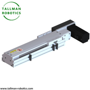
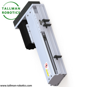
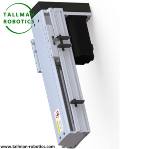


You are welcome to watch more projects or visit our website to check other series or load down e-catalogues for further technical data. Youtube: https://www.youtube.com/@tallmanrobotics Facebook: https://www.facebook.com/tallmanrobotics Linkedin: https://www.linkedin.com/in/tallman-robotics Read the full article
#ActuatorsinCartesianRobot#AutomationandRoboticswithElectricLinearActuator#Cartesianrobotic#Electriclinearactuators#IndustrialRobotslinearactuators#inearActuators#LinearActuator#Linearactuatorrobots#LinearActuatorsforRobotics#LinearMotionandActuatorsforSurgicalRobotics#Linearmotorsingleaxisrobots#LinearMotors&Actuators#Linearrobots#MicroLinearActuators#MultiStationBeltLinearActuator2AxisRobot#PrecisionLinearActuators#RobotActuators#RobotLinearActuators#RoboticArmwithLinearActuators#roboticslinearactuator#SingleAxisRobotLinearActuators#SingleAxisRobots#XYActuator(SingleRail)
0 notes
Text
Dive into Pneumatic Linear Actuator Tech
In the realm of automation and industrial machinery, the quest for efficiency, reliability, and precision is unceasing. One of the crucial components enabling this pursuit is the pneumatic linear actuator. These robust devices have become indispensable in a wide array of applications, from manufacturing and robotics to automotive and aerospace industries. Let's delve into the workings, applications, and advancements of pneumatic linear actuators, and explore how they're shaping the future of engineering and automation.
Understanding Pneumatic Linear Actuators
At its core, a pneumatic linear actuator is a mechanical device that converts compressed air energy into linear motion. The principle behind its operation is relatively simple yet effective. Compressed air is directed into the actuator's chamber, exerting force on a piston or diaphragm, which then moves along a linear path. This linear motion can be used to perform various tasks, such as opening or closing valves, lifting loads, positioning components, or actuating robotic arms.
Versatility in Applications
One of the key strengths of pneumatic linear actuators lies in their versatility. They find applications across a broad spectrum of industries
Manufacturing: In automated assembly lines, pneumatic linear actuators play a vital role in precise positioning and manipulating components. They ensure smooth and efficient operation, contributing to increased productivity and throughput.
Robotics: Pneumatic actuators are commonly used in robotic systems for tasks that require rapid and precise movement. Whether it's pick-and-place operations, material handling, or assembly tasks, these actuators provide the necessary force and speed.
Automotive: From automated welding and painting processes to assembly line operations, pneumatic actuators are integral to automotive manufacturing. Their reliability and robustness make them ideal for handling various tasks in the production of vehicles and their components.
Aerospace: In aerospace applications, where lightweight yet durable components are paramount, pneumatic actuators offer an excellent solution. They are utilized in aircraft systems for functions such as controlling flaps, landing gear, and cargo doors.
Medical: Pneumatic actuators play a crucial role in medical devices and equipment, such as surgical robots, patient handling systems, and diagnostic instruments. Their precise control and sterile operation make them indispensable in healthcare settings.
Advancements Driving Innovation
In recent years, advancements in materials, design, and control technologies have led to significant improvements in pneumatic linear actuators
Materials: The use of lightweight and high-strength materials, such as aluminum alloys and composite polymers, has resulted in actuators that offer better performance while minimizing weight and energy consumption.
Miniaturization: Miniature pneumatic actuators are becoming increasingly common, enabling their integration into compact and space-constrained applications, including medical devices, consumer electronics, and micro-robotics.
Smart Actuators: Integration of sensors, feedback systems, and advanced control algorithms has transformed pneumatic actuators into smart devices capable of precise motion control, adaptive performance, and self-monitoring capabilities.
Energy Efficiency: Efforts to improve energy efficiency have led to the development of pneumatic actuators with reduced air consumption and optimized performance characteristics, resulting in lower operating costs and environmental impact.
Future Prospects
As industries continue to embrace automation and robotics, the demand for pneumatic linear actuators is expected to grow. Advancements in materials science, sensor technology, and artificial intelligence will further enhance the capabilities and performance of these actuators, opening up new possibilities in areas such as collaborative robotics, wearable exoskeletons, and autonomous vehicles.
In conclusion, pneumatic linear actuators represent a cornerstone of modern engineering and automation. Their ability to convert compressed air into precise linear motion makes them indispensable across a wide range of industries and applications. With ongoing innovations driving their evolution, pneumatic actuators are poised to play an even more significant role in shaping the future of technology and industry.
1 note
·
View note
Text
8-Dec-2023
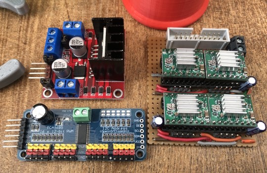
Now a little bit about extra electronic modules, that are readily available off the shelf. The modules shown in the picture and the reasons for using them is described below. There will be an update at some point showing a homemade hat to plug onto the top of the Pi, which is still having circuitry added to it and probably a Teensy Microcontroller to accurately measure the four distances from ultrasonic transducers plus the robot battery level. It might even do the PWM's aswel instead of the 16-Channel PWM board but we haven't decided on that yet.
4x Micro-Stepping motor driver modules mounted on a piece of FR2 Matrix Stripboard, for convenience of connecting to the RPi and the individual Short body Nema-17 Stepper motors. This way the motors can be controlled more accurately with direction and step pulse. These modules also provide current limiting and as stated, Micro-stepping which can provide smoother and better movement accuracy.
1x 16-channel PWM board to drive servos and probably LED’s to make the Robot a bit more flashy (Yet to be confirmed). The use of such a module is mainly because it is impossible to get a stable PWM from the Raspberry Pi. Most likely because the RPi PWM is a software generated pulse and not from a dedicated hardware counter, compounded by the Real time OS that is pulled in all manner of directions by higher priority level interrupts. It causes the PWM from the Pi OS to jitter like crazy, which in turn causes a servo to twitch rather a lot. So if you want accuracy and stability then a separate dedicated module is needed, as the RPi cannot provide either.
1x Dual H-Bridge. One of the channels is to drive the Boom’s 12V linear actuator. The second channel is spare in case we need it for some other hardware that we haven’t thought of yet.
0 notes
Text
Significance of Electrical Actuators in Today's Technological Landscape
In today's rapidly evolving technological landscape, the role of electrical actuators has become increasingly significant. These devices serve as critical components, powering a multitude of mechanical operations across various industries. Their importance lies in their ability to convert electrical energy into mechanical motion, facilitating precision, control, and automation in countless applications.
Introduction to Electrical Actuators
Electrical actuators are mechanisms designed to generate motion through electrical signals. They play a pivotal role in transforming energy, enabling the manipulation of various mechanisms in devices and systems. Their widespread use spans industries like automotive, aerospace and robotics fields.
Defining Electrical Actuators
At their core, electrical actuators are devices that translate electrical energy into mechanical movement. They are fundamental in controlling and regulating numerous functions, from simple adjustments to complex operations.
Importance in Various Industries
The versatility of electrical actuators makes them indispensable in modern industries. Their applications range from small-scale precision tasks to heavy-duty operations, contributing significantly to the advancement of technology.
Types of Electrical Actuators
Linear Actuators
These actuators produce linear motion, moving in a straight line. They find use in applications requiring controlled and precise movements, such as in robotics and automation.
Rotary Actuators
Rotary actuators, on the other hand, generate rotational motion, essential in mechanisms like valves, switches, and robotic arms.
Other Specialized Types
Beyond linear and rotary, specialized actuators cater to specific needs, like piezoelectric actuators for nano-scale applications or electrothermal actuators for micro-manipulation.
Applications Across Industries
Automotive Sector
Electrical actuators power crucial components in vehicles, including power windows, mirrors, and automated seat adjustments, enhancing comfort and safety.
Aerospace Industry
In aerospace, actuators control flight surfaces, landing gear, and other critical mechanisms, ensuring precise movements for safe and efficient operations.
Robotics and Automation
The evolution of robotics heavily relies on actuators, enabling robotic arms and joints to perform tasks with accuracy and agility in manufacturing and beyond.
Advantages and Benefits
Precision and Control
Electrical actuators offer unparalleled precision and control, allowing for exact positioning and movement in various applications.
Efficiency and Reliability
They enhance efficiency by executing tasks accurately and reliably, contributing to increased productivity across industries.
Customization and Adaptability
The adaptability of electrical actuators allows for customization, catering to diverse needs and technological advancements.
Challenges and Limitations
Technical Constraints
Some applications face limitations due to technical constraints, such as speed or force limitations of certain actuators.
Maintenance and Costs
Maintenance requirements and initial costs can pose challenges, especially in implementing these systems in smaller-scale applications.
Compatibility Issues
Integration of actuators into existing systems might encounter compatibility issues, requiring additional adjustments.
Technological Advancements
Recent innovations focus on improving materials, designs, and functionalities of actuators. Integration with IoT and AI promises smarter and more adaptive systems for the future.
Impact on Society and Future Trends
The growing reliance on automation and technological advancements driven by electrical actuators is reshaping industries. They pave the way for sustainable practices and enhanced capabilities, shaping a future where automation plays a more significant role.
Conclusion
Electrical actuators stand as pillars in today's technological landscape, powering innovations and advancements across industries. Their precision, efficiency, and adaptability continue to drive progress, promising a future where automation and control redefine possibilities.
FAQs
Q- Are electrical actuators essential for all industries?
A- While not essential for all, their significance is notable across various sectors, contributing to efficiency and precision.
Q- What challenges do electrical actuators face in their implementation?
A- Technical constraints, maintenance costs, and compatibility issues are primary challenges.
Q- How do electrical actuators contribute to technological advancements?
A- They enable precise control and automation, fostering innovations in diverse fields.
Q- Are there specific industries benefiting most from electrical actuators?
A- Industries like automotive, aerospace and robotics fields highly rely on their functionalities.
Q- What does the future hold for electrical actuators?
A- Continued advancements in materials and integration with AI and IoT, shaping smarter and more adaptable systems.
1 note
·
View note
Text
Apollo Micro Systems' Groundbreaking Agreements with DRDO: A Leap in Defense Technology
In the bustling heart of Mumbai’s financial district, Apollo Micro Systems Limited is making waves in the world of technology and innovation. On September 23, 2023, the company, headquartered at the iconic Phiroze Jeejeebhoy Towers, made a momentous announcement. In a letter addressed to the Department of Corporate Services at BSE Limited and the Listing Department at the National Stock Exchange of India Ltd., Apollo Micro Systems unveiled a series of groundbreaking agreements with the Defence Research and Development Organisation (DRDO).
These agreements not only represent a significant leap forward in Apollo Micro Systems’ business operations but also underline the company’s unwavering commitment to strengthening its collaboration with DRDO. Let’s delve into the details of these game-changing agreements and understand their implications.
The Significance of the Agreements
Transfer of Technology for Guidance and Navigation: The first agreement involves the Transfer of Technology (ToT) for Guidance and Navigation. This technology holds immense potential in both domestic and international markets. It is used to convert conventional non-guided weapons into guided ones, a breakthrough with far-reaching implications for defense capabilities. Apollo Micro Systems has been working closely with DRDO on this technology and has now been selected as a ToT Partner through a Licensing Agreement for Transfer of Technology.
Weaponization of Hand-Held Thermal Imager with LRF (WHHTI): This cutting-edge technology involves the weaponization of a Hand-Held Thermal Imager with Laser Range Finder (LRF). WHHTI is a state-of-the-art weaponization platform featuring an Electro-Optical System that meets the requirements of monitoring border areas and sensitive regions. It also aims to provide remotely operated countermeasures to neutralize threats under various conditions. The system’s technical features include enhancing existing HHTIs, enabling observation and engagement from a protected location, and increasing operational efficiency. This innovation eliminates the need for two soldiers to carry out surveillance and threat-neutralizing activities, reducing the chances of miscommunication or human error.
Rotary Electro-Mechanical Actuator: In another groundbreaking collaboration, Apollo Micro Systems has partnered with DRDO to develop Linear and Rotary Electro-Mechanical Actuators for various capacities. These actuators play a crucial role in defense applications. The company has been selected as a ToT Partner through a Licensing Agreement for the Transfer of Technology.
Unified Avionics Computer: The Unified Avionics Computer represents a complex on-board subsystem critical to weapons. It houses control, guidance, and navigational algorithms vital for precision. Apollo Micro Systems has been working closely with DRDO on this technology, and it has now been chosen as a ToT Partner through a Licensing Agreement for Transfer of Technology.
A Remarkable Milestone in Collaboration
These agreements mark a significant milestone in Apollo Micro Systems’ ongoing partnership with DRDO. They signify the company’s commitment to excellence in technology and innovation, especially in defense-related projects. The scope of these agreements encompasses a wide array of defense technologies, from guidance and navigation to thermal imaging, actuators, and avionics.
As Apollo Micro Systems continues to push the boundaries of technological innovation, it reinforces its position as a key player in India’s defense technology landscape. These agreements are not just contracts; they are testaments to the power of collaboration, innovation, and the relentless pursuit of excellence.
Apollo Micro Systems’ disclosure of these agreements with DRDO is a momentous occasion for the company and the Indian defense sector. It highlights the remarkable strides being made in the field of defense technology, showcasing India’s potential as a global leader in innovation. As we eagerly await the outcomes of these collaborations, one thing is certain: Apollo Micro Systems is poised for a future marked by groundbreaking advancements in defense technology.
0 notes
Text
#newscaletechnolgies#electroverge#electroniccomponents#business#digitalcommunications#M3 micro-stages#M3-LS linear stages#M3-FS focus modules#M3-L linear actuators
0 notes
Link
The IR Robot mightyZAP is an All in One solution having a built-in drive circuitry. It can be applied in various fields such as factory automation, medical devices, robotics etc.
#micro linear servo actuator#mightyZAP micro linear servo actuator#IR Robot Mini Linear Servo Actuator#IR Robot mightyZAP#mightyZAP micro linear#Micro Linear Servo Actuator mightyZAP#mightyZAP
0 notes
Text
Micro Linear Actuator Motor for Intelligent Transmission Enables Smart Life
Modern science and technology have succeeded in helping people live independently and conveniently in a smart way. According to Smart Home Report 2019 conducted by Statista, revenue related to the whole Smart Home market is expected to show an annual growth rate (CAGR 2020-2024) of 16.8%, resulting in a projected market volume of US$157,287m by 2024. A global comparison reveals that most revenue is generated in the United States (US$24,972m in 2020). It is obvious that people’s awareness of people’s quality of life is continuously enhanced. In the pursuit of ideal performance for most of the smart home systems, micro linear actuator motors come into play.
Micro Linear Actuator Motor Comes to Simplify the Life
ZHAOWEI transmits the instructions to the mechanical structure, so that the circular motion of the motor is converted into the linear motion of the linear actuator, achieving pushing & pulling and able to lift heavy objects. Electric linear actuator motor provided by ZHAOWEI is a linear device with lifting function that mainly consists of motor, lead screw and control system, which can realize remote control as well as centralized control. The rod of the electric actuator makes round-trip lifting movement within a certain range of distance. Customization for development is always available so that the miniature linear screw can be used in various fields that needs lifting movement, such as medical beds, standing desks and diverse equipment for industrial and agricultural automation. ZHAOWEI micro linear actuator motor makes standing systems more intelligent, more convenient and more diversified.
There are many sets of smart electric lifting furniture on the current market, but some problems still occur such as insufficient load bearing, limited switchable gear(lifting range), short service life, large power consumption, loud noise or even stuttering if the speed is not controlled well while lifting. By introducing the micro linear actuator motors produced by ZHAOWEI, those anxieties can be removed. Its micro linear actuator motor for lifting movement enables compact size with no external control board. The whole working process of this kind of micro linear actuator motor leads to its good stability, strong synchronization performance, low noise and high torque. High-precision design with high torque helps to deliver high performance in applications requiring continuous duty operation. Though it is small, it still has a strong power to facilitate each project with low noise.
Smart Home Drive with Micro Linear Actuator Motor Enriches the Life
ZHAOWEI is also shaping smart life by micro linear actuator motor transmission technology, which can realize various automatic functions in the fields of smart home, smart office and smart hotel. Intelligent electric curtains and automatic clothes drying rack are two of the typical cases that contribute to smart life.
Intelligent Electric Curtains
Living in the city is where the fast-paced people usually are. However, more and more people are in the pursuit of a simple and convenient lifestyle. Smart electric curtains happen to meet such needs, which are very practical and can be installed at home and in office.
As for the general intelligent solution to electric curtains on the market, noise often appears in daily operation, which becomes one of the biggest problems. No matter at home or in office, people must attach great importance to a quiet environment. To tackle such a pain point, ZHAOWEI adopts herringbone gear design to greatly reduce the noise from the tubular planetary motor, thus improving the quality of life.

This electric curtain gear motor solution also takes pride in compact size, high torque, long service life and reliable operation due to its extremely large single-stage gear ratio and robust construction. It consists of an involute planetary gear reduction mechanism and cycloidal gear reduction mechanism. The power of the former is transmitted to the latter. The involute planetary gear reduction mechanism includes a planetary gear and a sun gear while the planetary gear has a mandrel, which is fixedly connected to the first planet carrier. The cycloidal gear reduction mechanism includes a camshaft, whose end is fixedly connected to the first planetary carrier. A cycloidal gear is set on the cam of the camshaft and a pinwheel is provided outside the cycloidal gear. Then the cycloidal gear can be cycloid and rotated around the camshaft. There is a pin connected to the output shaft on the cycloidal gear, so that the power decelerated by the cycloidal gear reduction mechanism can be transmitted to the output shaft through the pin. The cycloidal movement makes the cycloidal gear and the pinwheel squeeze each other to get better movement coincidence, resulting in a good self-locking performance for curtain & blind protection.
Automatic Clothes Drying Rack
The intelligent electric drying rack is favored and used by more and more families because of its convenient operation, various functions, novel style and exquisite appearance. All these can benefit from an outstanding gear motor provided by ZHAOWEI, which consists of the motion system driven by the motor, intelligent control system and metal frame. The ceiling mount automatic clothes drying rack is operated to up and down by smooth control. It can be integrated with lighting, sound control, remote control, drying & sterilizing system, making each automatic clothes drying rack more powerful. The parameters including speed, current, gear ratio, etc. of gear motor for automatic clothes drying rack can be fully customized based on different needs. Thus, automatic clothes drying rack is not only a drying tool, but also becomes an ornament in the appearance, electric clothes drying rack already becomes a landscape in the balcony.
“We’ve been coming up with innovative linear movement solutions with a passion for precision and next-level purpose for intelligent control,” says the Project Manager. “We always strive to make your home & office life more comfortable and fulfill your beautiful imagination of life by such an intelligent transmission system with the micro linear actuator motor!”
0 notes
Text
Differences Between Smart Pressure Transmitter and Analog Pressure Transmitter
Pressure transmitter is composed of single chip microcomputer and micro displacement (differential) pressure sensitive element, which can complete multi-function detection and conversion from non electric quantity to electric quantity.

Figure 1: Rosemount Smart Transmitter
With the development of microprocessor technology and digital communication technology, smart pressure transmitter is produced. It is a new type of pressure transmitter with digital processing and digital communication ability. The so-called smart pressure transmitter uses microprocessor in the pressure transmitter. Through software, the use of microprocessor can realize some functions that analog pressure transmitter cannot achieve. Compared with traditional analog pressure transmitter, smart pressure transmitter has the following advantages.
Communication Ability
When the smart pressure transmitter is connected with DCS adopting the same communication protocol, it can carry out direct two-way digital communication. The smart pressure transmitter can be adjusted by remote control in the control room through the manual terminal, while the analog pressure transmitter can only be adjusted in the field. The calibration of zero point and range of smart pressure transmitter is independent, which can be completed only once.
Self - Diagnosis Ability
When using the pressure transmitter, you can find the correct and clear fault information on the manual terminal or the screen of DCS, which makes it convenient for the maintenance personnel to quickly remove the fault, improving the reliability and availability of the system of transmitter.
Function of PID (Proportional Integral Derivative) Controller
The function of PID controller is added to the transmitter by software, so that the pressure transmitter has the function. This pressure transmitter can be directly connected with the actuator, so smart pressure transmitter is promising.
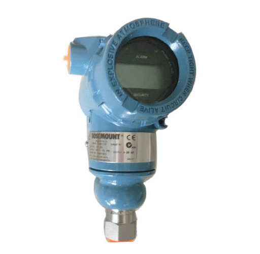
Figure 2: Rosemount Smart Transmitter 3051TG1A2C21AB4M5I5
Measurement Range
The smart pressure transmitter has a larger measurement range. *Measurement range = Maximum range / Working range *Maximum measurement range = Maximum range / Minimum working range Therefore, large measurement range reduces specifications of the transmitter.
Strong Stability
Generally, smart pressure transmitter has reliable temperature compensation and static pressure compensation. The detection principle of smart pressure transmitter mainly includes capacitive type, diffusion silicon type and inductive type, and the first two types are the main types. The output signals of smart pressure transmitter are analog (4 - 20mA) and digital. In addition to linear and square root output signals, some transmitter products can also output PID operation signal, which are also called smart transmission controller. Smart pressure transmitters have been used in China since 1990s. At present, there are more than ten series of pressure transmitters from nearly ten manufacturers in the market.
More information please visit https://okmarts.com/
2 notes
·
View notes
Link
The Micro Pen Linear Actuator offers a powerful yet slim inline design. The light weight and slender dimensions only measuring 16mm in diameter are idea...
1 note
·
View note