#pi 4 high performance camera module
Explore tagged Tumblr posts
Visit Tumblr Blog
Explore Tumblr blogs with no restrictions, modern design and the best experience.
Last Seen Tumblr Blogs


Fun Fact
Celebrities use Tumblr as well.
Text
Exploring the Possibilities with Raspberry Pi: A Guide to Buying and Utilizing Raspberry Pi 4 and Its Camera Kit
Introduction:
In the world of single-board computers, Raspberry Pi stands out as a powerful and versatile option. The Raspberry Pi Foundation has continuously pushed the boundaries of what can be achieved with these compact devices. In this blog post, we will explore the benefits of Raspberry Pi 4 kit, Raspberry pi buy, and delve into the exciting projects you can undertake using this remarkable technology.
Why Choose Raspberry Pi 4 Camera? Raspberry pi 4 camera is the latest iteration of the Raspberry Pi series, offering improved performance and enhanced features. It comes equipped with a Broadcom BCM2711 quad-core Cortex-A72 processor, clocked at 1.5GHz, which ensures smooth multitasking and faster execution of complex tasks. The availability of up to 8GB of RAM allows for efficient handling of data-intensive applications. With its support for dual-band Wi-Fi and Bluetooth 5.0, Raspberry Pi 4 provides seamless connectivity options for your projects.
Exploring the Camera Capabilities: One of the most exciting features of Raspberry Pi 4 is its compatibility with a dedicated camera module. The Raspberry Pi Camera Module v2 is a high-quality camera that can be easily connected to the board via the camera interface. The camera module offers an 8-megapixel sensor and supports video resolutions up to 1080p, enabling you to capture stunning photos and videos. Its compact size and versatility make it perfect for various applications, including surveillance systems, time-lapse photography, and even computer vision projects.
Where to Buy Raspberry Pi 4 Online: When it comes to purchasing Raspberry Pi 4 and its accessories online, there are several reputable platforms to consider. Some popular options include:
Online Retailers (e.g., Amazon, Robomart, SparkFun) Established Raspberry pi buy online platforms like Amazon, Robomart, and SparkFun also stock Raspberry Pi 4 boards, camera modules, and kits. These retailers often provide customer reviews and ratings, giving you insights into the products before making a purchase.
Specialized Electronics Retailers Various specialized electronics retailers cater specifically to the Raspberry Pi community. These retailers often have a wide range of Raspberry Pi products, including kits that include the camera module.
Exciting Raspberry Pi 4 Projects: Once you have your Raspberry Pi 4 and camera kit, the possibilities for projects are virtually endless. Here are a few ideas to get you started:
Home Surveillance System: Set up a motion-activated camera system to monitor your home remotely and receive alerts on your smartphone.
Wildlife Monitoring: Create a wildlife camera trap that captures photos or videos of animals in their natural habitats.
Time-Lapse Photography: Capture the beauty of nature or the progress of a construction project by creating stunning time-lapse videos.
Facial Recognition: Develop a facial recognition system using the camera module and explore applications in security or access control.
Virtual Assistant: Transform your Raspberry Pi 4 into a voice-controlled assistant by integrating a microphone and speaker.
Conclusion: Raspberry Pi 4, along with its camera module, opens up a world of possibilities for hobbyists, educators, and professionals alike. Whether you're interested in building a smart home system or exploring computer vision applications, Raspberry Pi 4 provides the necessary power and flexibility. With numerous online platforms available to purchase Raspberry Pi 4 and its accessories,
4 notes
·
View notes
Text
Why India’s Drone Industry Needs Periplex: The Hardware Tool Drones Didn’t Know They Needed
As drones fly deeper into critical roles — from agricultural intelligence to autonomous mapping, from disaster response to military ops — the hardware stack that powers them is undergoing a silent revolution.
At the center of that transformation is Periplex — a breakthrough tool from Vicharak’s Vaaman platform that redefines how drone builders can interface with the real world.

What is Periplex?
Periplex is a hardware-generation engine. It converts JSON descriptions like this:{ "uart": [ { "id": 0, "TX": "GPIOT_RXP28", "RX": "GPIOT_RXN28" } ], "i2c": [ { "id": 3, "SCL": "GPIOT_RXP27", "SDA": "GPIOT_RXP24" }, { "id": 4, "SCL": "GPIOL_63", "SDA": "GPIOT_RXN24" } ], "gpio": [], "pwm": [], "ws": [], "spi": [], "onewire": [], "can": [], "i2s": [] }
…into live hardware interfaces, directly embedded into Vaaman’s FPGA fabric. It auto-generates the FPGA logic, maps it to kernel-level drivers, and exposes them to Linux.
Think of it as the “React.js of peripherals” — make a change, and the hardware updates.
Real Drone Applications That Truly Need Periplex
Let’s break this down with actual field-grade drone use cases where traditional microcontrollers choke, and Periplex thrives.
1. Multi-Peripheral High-Speed Data Collection for Precision Agriculture
Scenario: A drone is scanning fields for crop health with:
2 multispectral cameras (I2C/SPI)
GPS + RTK module (2x UART)
Wind sensor (I2C)
Sprayer flow monitor (PWM feedback loop)
ESCs for 8 motors (PWM)
1 CAN-based fertilizer module
The Periplex Edge: Microcontrollers would require multiple chips or muxing tricks, causing delays and bottlenecks. With Periplex:
You just declare all interfaces in a JSON file.
It builds the required logic and exposes /dev/pwm0, /dev/can0, etc.
Zero code, zero hassle, zero hardware redesign.
2. Swarm Communication and Custom Protocol Stacks
Scenario: Swarm drones communicate over:
RF LoRa (custom SPI/UART)
UWB mesh (proprietary protocol)
Redundant backup over CAN
Periplex lets you:
Create hybrid protocol stacks
Embed real-time hardware timers, parity logic, and custom UART framing — none of which are feasible in most MCUs
Replacing Microcontrollers, Not Just Augmenting Them
| Feature | Microcontroller | Periplex on Vaaman | |---------------------------|----------------------------|------------------------------------| | Number of peripherals | Limited (4–6) | Virtually unlimited (30+ possible) | | Reconfiguration time | Flash + reboot | Real-time, dynamic reload | | Timing precision | Software-timer limited | FPGA-grade nanosecond-level timing | | AI compatibility | Not feasible | Integrated (Gati Engine) | | Sensor fusion performance | Bottlenecked | Parallel FPGA pipelines |
Developers Love JSON, Not Register Maps
No more:
Scouring 400-page datasheets
Bitmasking registers for I2C configs
Writing interrupt handlers from scratch
Just declare what you need. Let Periplex do the work. Peripherals become software-defined, but hardware-implemented.
Built in India, for India’s Drone Revolution
Vaaman + Periplex isn’t just about tech. It’s about self-reliance.
India’s defence, agriculture, and logistics sectors need secure, reconfigurable, audit-friendly hardware — not black-box SoCs from questionable supply chains.
Periplex is the hardware engine for Atmanirbhar Bharat in drones.
TL;DR
Periplex lets drones adapt hardware to the mission — instantly.
It replaces tangled microcontroller logic with clean, structured JSON.
It unlocks use cases microcontrollers can’t touch: AI at the edge, dynamic reconfiguration, secure protocol stacks, and more.
And it’s built into Vaaman, India’s first reconfigurable edge computer.
Ready to Get Started?
Explore Vaaman on Crowd Supply Reach out for Periplex SDK access: [email protected]
Raspberry Pi
Drones
Drones Technology
Jetson Orin Nano
Technology
0 notes
Text
Elmalo, let's commit to that direction. We'll start with a robust Sensor Fusion Layer Prototype that forms the nervous system of Iron Spine, enabling tangible, live data connectivity from the field into the AI's processing core. Below is a detailed technical blueprint that outlines the approach, components, and future integrability with your Empathic AI Core.
1. Hardware Selection
Edge Devices:
Primary Platform: NVIDIA Jetson AGX Xavier or Nano for on-site processing. Their GPU acceleration is perfect for real-time preprocessing and running early fusion algorithms.
Supplementary Controllers: Raspberry Pi Compute Modules or Arduino-based microcontrollers to gather data from specific sensors when cost or miniaturization is critical.
Sensor Modalities:
Environmental Sensors: Radiation detectors, pressure sensors, temperature/humidity sensors—critical for extreme environments (space, deep sea, underground).
Motion & Optical Sensors: Insect-inspired motion sensors, high-resolution cameras, and inertial measurement units (IMUs) to capture detailed movement and orientation.
Acoustic & RF Sensors: Microphones, sonar, and RF sensors for detecting vibrational, audio, or electromagnetic signals.
2. Software Stack and Data Flow Pipeline
Data Ingestion:
Frameworks: Utilize Apache Kafka or Apache NiFi to build a robust, scalable data pipeline that can handle streaming sensor data in real time.
Protocol: MQTT or LoRaWAN can serve as the communication backbone in environments where connectivity is intermittent or bandwidth-constrained.
Data Preprocessing & Filtering:
Edge Analytics: Develop tailored algorithms that run on your edge devices—leveraging NVIDIA’s TensorRT for accelerated inference—to filter raw inputs and perform preliminary sensor fusion.
Fusion Algorithms: Employ Kalman or Particle Filters to synthesize multiple sensor streams into actionable readings.
Data Abstraction Layer:
API Endpoints: Create modular interfaces that transform fused sensor data into abstracted, standardized feeds for higher-level consumption by the AI core later.
Middleware: Consider microservices that handle data routing, error correction, and redundancy mechanisms to ensure data integrity under harsh conditions.
3. Infrastructure Deployment Map
4. Future Hooks for Empathic AI Core Integration
API-Driven Design: The sensor fusion module will produce standardized, real-time data feeds. These endpoints will act as the bridge to plug in your Empathic AI Core whenever you’re ready to evolve the “soul” of Iron Spine.
Modular Data Abstraction: Build abstraction layers that allow easy mapping of raw sensor data into higher-level representations—ideal for feeding into predictive, decision-making models later.
Feedback Mechanisms: Implement logging and event-based triggers from the sensor fusion system to continuously improve both hardware and AI components based on real-world performance and environmental nuance.
5. Roadmap and Next Steps
Design & Prototype:
Define the hardware specifications for edge devices and sensor modules.
Develop a small-scale sensor hub integrating a few key sensor types (e.g., motion + environmental).
Data Pipeline Setup:
Set up your data ingestion framework (e.g., Apache Kafka cluster).
Prototype and evaluate basic preprocessing and fusion algorithms on your chosen edge device.
Field Testing:
Deploy the prototype in a controlled environment similar to your target extremes (e.g., a pressure chamber, simulated low-gravity environment).
Refine data accuracy and real-time performance based on initial feedback.
Integration Preparation:
Build standardized API interfaces for future connection with the Empathic AI Core.
Document system architecture to ensure a smooth handoff between the hardware-first and AI-core teams.
Elmalo, this blueprint establishes a tangible, modular system that grounds Iron Spine in reality. It not only demonstrates your vision but also builds the foundational “nervous system” that your emergent, empathic AI will later use to perceive and interact with its environment.
Does this detailed roadmap align with your vision? Would you like to dive further into any individual section—perhaps starting with hardware specifications, software configuration, or the integration strategy for the future AI core?
0 notes
Text
Cutting-Edge Automation: The AR0234 USB Camera Advantage
Superior imaging technologies are critical in the quickly changing field of automation and robotics. The AR0234 USB Camera sticks out among the plethora of options available as a cutting-edge instrument that promises to revolutionize automation systems. With its remarkable features and capabilities, this cutting-edge camera module is revolutionizing industries with its unmatched imaging performance and dependability. In this blog post, we'll look at the benefits of the AR0234 USB camera and how it affects cutting-edge automation.
Unveiling the AR0234 USB Camera
The AR0234 USB Camera is a state-of-the-art imaging solution designed to meet the demanding requirements of modern automation systems. At its core, this camera features the AR0234 CMOS image sensor, known for its exceptional image quality, high resolution, and impressive low-light performance. With a pixel size of 3.0 µm and a resolution of 2.3 megapixels, the AR0234 sensor ensures crisp, clear images even in challenging lighting conditions.
The integration of the AR0234 sensor with a USB interface makes the AR0234 USB Camera a versatile and user-friendly solution. The USB interface simplifies connectivity, allowing seamless integration with various devices and systems, including industrial robots, automated inspection systems, and smart surveillance setups.
Advantages of the AR0234 USB Camera
1. Superior Image Quality
One of the most significant advantages of the AR0234 USB camera is its superior image quality. The AR0234 sensor excels in capturing high-resolution images with remarkable clarity and detail. This is crucial for applications such as quality control in manufacturing, where precise image analysis is essential to detect defects and ensure product standards.
2. Enhanced Low-Light Performance
Automation systems often operate in environments with varying lighting conditions. The AR0234 USB Camera's excellent low-light performance ensures that it can capture clear images even in dimly lit settings. This capability is particularly beneficial for surveillance and security applications, where reliable imaging is needed around the clock.
3. High Frame Rate
The AR0234 USB camera supports high frame rates, making it ideal for applications that require real-time imaging and analysis. With frame rates of up to 120 frames per second (fps) at full resolution, this camera can handle fast-moving objects and dynamic scenes with ease. This feature is invaluable in robotics, where rapid image processing is critical for tasks such as object recognition and tracking.
4. Versatile Connectivity
The USB interface of the AR0234 USB Camera provides versatile connectivity options, simplifying integration with various platforms. Whether it's connected to a PC, a Raspberry Pi, or an embedded system, the AR0234 USB Camera ensures smooth and reliable communication. This flexibility makes it a go-to choice for developers and engineers working on diverse automation projects.
5. Robust and reliable
Designed for industrial applications, the AR0234 USB camera is built to withstand harsh environments. Its robust construction and reliable performance ensure longevity and durability, reducing the need for frequent replacements and maintenance. This reliability translates to cost savings and uninterrupted operation of critical automation systems.
Applications of the AR0234 USB Camera in Automation
The AR0234 USB Camera finds applications across various automation domains, thanks to its advanced features and capabilities. Here are a few notable examples:
1. Industrial Inspection
In manufacturing, the AR0234 USB camera is employed for automated inspection and quality control. Its high-resolution imaging and precise detail capture enable the detection of defects and inconsistencies in products, ensuring that only high-quality items reach the market. This enhances productivity and reduces waste.
2. Robotics
Robotic systems rely on accurate vision to perform tasks such as picking, placing, and assembling components. The AR0234 USB camera's high frame rate and exceptional image quality make it an excellent choice for robotic vision systems. It enables robots to accurately identify objects, navigate environments, and interact with their surroundings.
3. Surveillance and Security
For surveillance and security applications, the AR0234 USB camera provides reliable performance in various lighting conditions. Its low-light capabilities and high-resolution imaging ensure clear and detailed footage, enhancing the effectiveness of security systems. Whether it's monitoring a facility or a public space, this camera contributes to improved safety and security.
4. Smart Cities
As cities become smarter and more connected, the need for advanced imaging solutions grows. The AR0234 USB camera can be integrated into smart city infrastructure to monitor traffic, manage public spaces, and enhance urban security. Its versatility and performance make it a valuable asset in the development of intelligent urban systems.
In summary
An innovative image solution with several benefits for automation systems is the AR0234 USB Camera. It is an exceptional option for a variety of applications due to its strong design, high frame rate, flexible connectivity, improved low-light performance, and higher image quality. The AR0234 USB Camera is advancing automation innovation and efficiency in a variety of fields, including smart cities, robotics, industrial inspection, and surveillance.
The AR0234 USB Camera is positioned to have a significant impact on the future as companies continue to adopt automation and smart technology. Because of its cutting-edge features and capabilities, businesses can be empowered to attain unprecedented levels of productivity, precision, and dependability. It will continue to be at the forefront of imaging solutions. Accept the benefits of the AR0234 USB camera and realize the full potential of state-of-the-art automation.
0 notes
Photo

Camera modules for the Raspberry Pi 4: We will be releasing them soon!
Read the blog here: http://bit.ly/cams-Pi-4
Buy some of our cool cams here: http://bit.ly/Buy-Arducam
#raspberry pi 4 module#raspberry pi 4 model b#pi 4 camera module#raspberry 4 cameras#pi 4 module B camera module#pi 4 high performance camera module#raspberry pi 4 cameras#pi 4 official camera module#raspberry pi 4 projects#buy raspberry 4 cameras#pi 4 camera adapter#pi 4 high definition cam#Arducam Pi 4#Raspberry pi 4 Camera USB 3.0#Pi 4 Multi-camera support
0 notes
Text
[Something awesome] Blog #1
This is my first iteration of facial recognition software that I tried to implement it. Although there is a long way to go but this is my first iteration.
There are several ways to do facial recognition at this time. A number of open-source software specifically implemented for the scenario of object detection are provided with a bunch of tutorials. OpenCV is the one I decided to work on.
The content below consist of how my study about the algorithm behind facial recognition application works (I might not so good at explaining things, but hope you can understand at least what a classifier is :D) and the example of using OpenCV in the simple tutorial I learned.
OpenCV
An open-source computer vision module works in the various programming language (mostly python and C++). This module can allow the developer to implement an object detection software and other kinds of computer vision project.
Facial detection
Facial detection is a branch of machine learning developed from object detection area, where a (usually machine learning) model has to be created by feeding a set of large images of the object, which is a human face in this project.
There are 2 types of the image used to train the model
Positive image
Negative image
For example, if I would like to detect Trump’s face, a positive image is obviously his face while the negative image can be anything having no face of him. Our program would perform based on these set of data.

The next question is “How the algorithm behind model works?”. There is one facial detection approach called “Haar Cascades” proposed by Paul Viola and Michael Jones in 2001. It uses Haar-feature (Proposed by Alfred Haar in 1909) to analyse images (idea is pretty much similar to Fourier-analysis).
Haar Cascade Classifier
To break it down into simple explanation, I would start with how “Haar features” works to detect human face by using most relevant features on the face such as eyes, eyebrows, nose, lips, etc...
In order to detect an object in the image, we need a cascade classifier to classify that there is an object or not; however, it is very difficult to create one single classifier having high complexity at once. Haar-feature makes this process easier by concatenation a huge set of simple classifiers, resulting in a more complex one.
Example of simple classifiers that being used to build a strong classifier

As you can see at his eye from the picture above, the color of a region below eyebrow is obviously darker than the area above it. This point can be used as a relevant feature to detect a human face. The same logic is applied to the nose area, where the region at the middle is brighter than the left and right sides.

Applying some simple classifier into the areas mentioned above, the result will look like this.

All the logic above is used to make a calculation by comparing lighter and darker intensities in each pixel of a positive image (picture that has an object), concatenate them together and create a strong classifier for the individual face.

OpenCV module tutorial result
Here is a good resource I found in installing the module (for mac). I spent around 4 hours just to install it. It is all my fault in taking that long because I am not so expert in managing the library on my laptop. We all know right? setting up the module is one of the most difficult parts of coding LOL.
I followed the tutorial here to make a simple OpenCV program working on my laptop front camera. I had ordered Raspberri pi 3 model B+ and It has not shipped yet, I would test on it once all the basic component has arrived. The link below is the result of the first iteration of using it in facial detection areas.
Video of Haar-cascade facial recognition test
I still not 100% understand about how to use OpenCV, so I would not explain it at this time; however, I would love to make a tutorial or a guide of using it once I become more confident in using it.
1 note
·
View note
Text
Power Management IC Market: 2021 Growth, Opportunities and Forecast 2023
Market Research Future published a research report on “Power Management IC Market Research Report - Global Industry Forecast To 2023” – Market Analysis, Scope, Stake, Progress, Trends and Forecast to 2023.
Market Insight
The global power management IC market is cementing its foothold due owing to the traction generated by information and communication sector globally, thus expecting an exponential expansion with 8.8% CAGR during the forecast period (2018-2023), declares Market Research Future (MRFR). The valuation of the market is also recorded as USD 38,388.9 Mn to achieve in the same period. The study encompasses several thriving factors and drivers that are contributing to the market’s growth in the present as well as in the future. PMIC includes a broad range of chips and can be integrated into battery-operated devices, such as mobile phones and portable media players.
Market Drivers & Trends
According to the report published by MRFR, the rising miniaturing trend in the electronics industry has a massive impact which is the chief Power Management IC Market influencer. Apart from the information and communication sector, it is also getting popular with consumer electronics sector being a significant end-user of PMIC, which can be a great boon for the global power management IC market.
On the other hand, the factors such as the need for efficient power, high density and design flexibility of power modules are supporting the market growth inevitably. At the same time, the growth of silicon-carbide (SiC) and gallium nitride (GaN) are also likely to open new growth opportunities for market players going forward and acquire more valuation. On the flip side, the factor of development issues in multi-power domain SoCs can limit the adoption rate of power management IC in the coming years, thus restricting the market growth in the forecast period.
Get Free Sample Report @ https://www.marketresearchfuture.com/sample_request/5038
Key Players
Some of the key players in the market are Texas Instruments Inc. (U.S.), ON Semiconductor Corp. (U.S.), Analog Devices, Inc. (U.S.), Dialog Semiconductor PLC (U.K.), Maxim Integrated Products, Inc. (U.S.), STMicroelectronics N.V. (Switzerland), and Linear Technology Corp. (U.S.), Renesas Electronics Corporation (Japan), Toshiba Corporation (Japan), among others.
Market Segmentation:
MRFR’s study includes a detailed segmental analysis of global power management IC market based on product and application.
By the mode of product, the market has included various segments such as integrated ASSP power management IC, motor control IC and voltage regulators. The integrated ASSP power management segment is further sub-segmented into battery management IC, LED drivers ICs, PFC controllers hot-swap controllers, wireless charging ICs, energy management ICs, PoE controllers. The segment is likely to remain extremely attractive during the estimation period and post a CAGR of 9.3% as there was an uptick in the adoption of integrated ASSP power management IC for its high-performance characteristics.
By the mode of application, the market included consumer and wearable electronics, telecom and networking and automotive. The consumer and wearable electronics segment, therefore, stood at a valuation of USD 9,275.6 Mn in 2017 and is now expected to remain highly attractive in 2019 and would expand at a striking pace over the next couple of years. Sales of consumer and wearable electronics such as smartwatches, cameras, smartphones, TVs, laptops and fitness bands have consistently grown in recent years, which have been driving the segment’s growth.
Detailed Regional Analysis:
According to regional analysis, the study of global power management IC market has covered the main regions of North America, Europe, Asia Pacific, Latin South America and the Middle East & Africa (MEA).
Among these, in 2017, Asia Pacific (APAC) held for the largest market share in terms of value and is now anticipated to witness a CAGR of 8.9% in the forecast period. APAC region is led by China that offers lucrative market avenues and is the go-to destination for all the market players related to the market. Economic surge and incidence of a massive semiconductor industry are some of the key factors boosting the market share in the region. Furthermore, the incidence of a large number of wafer fabrication manufacturers is also contributing the market growth in APAC. China makes a noteworthy contribution to the global semiconductor component supply, which characterizes its strong position in the market.
In North America region, the power management integrated circuit market is increasing at an extensive rate, as the Brazilian government is doing hard work to attract prominent companies to invest in their production plans of semiconductor plants. Furthermore, the companies involved in these plans will be exempted from federal taxes, such as ISS, COFINS, and PIS. Additionally, this region is also witnessing the intensifying demand for energy-efficient LED lights, portable devices, and electric vehicles, which will likely to drive the power management IC market in the future.
The European region is likely to drive the market over the forecasted period due to the rising number of R&D activities witnessed in the automation sector and portable devices for achieving more energy efficiency. Even the manufacturers in the European region are developing customized solutions in intergraded circuits to meet the developing demand in various industrial applications.
Get complete Report @ https://www.marketresearchfuture.com/reports/power-management-ic-market-5038
TABLE OF CONTENTS
LIST OF TABLES
Table 1 Market Synopsis
Table 2 List Of Assumptions
Table 3 Global Power Management Integrated Circuit (Pmic) Market, By Product, 2017–2023 (Usd Million)
Table 4 Global Power Management Integrated Circuit (Pmic) Market, By Application, 2017–2023 (Usd Million)
Continued…
Get New Updates @ https://www.linkedin.com/company/ict-mrfr
About Us:
At Market Research Future (MRFR), we enable our customers to unravel the complexity of various industries through our Cooked Research Report (CRR), Half-Cooked Research Reports (HCRR), Raw Research Reports (3R), Continuous-Feed Research (CFR), and Market Research & Consulting Services.
Media Contact:
Market Research Future
Office No. 528, Amanora Chambers
Magarpatta Road, Hadapsar,
Pune - 411028
Maharashtra, India
+1 646 845 9312
Email: [email protected]
0 notes
Text
Biomed Grid| A Guide to Select Sensors for Biomedical Propose
Abstract
After Implementing an external device in a patient, it is crucial to monitor it. The challenge of being inside the patient and the need to perform the chirurgical operation to observe the evolution and state is a major step to do. Also, the communication process is not easy. On the top, the rejection avoidance of a strange body and the critical environment presents an additional motivation. The present paper presents a detailed study sensor for a wide range of biomedical proposes and applications. It aims to explain and synthetize complex technical knowledge in a simple and comprehensible language.
Keywords: Sensor, Monitoring, Nanotechnology, Biomaterials, Implants, Data acquisition, Medical
Introduction
In basic terms, the sensor is a device that makes the detection and responds with an input from the physical environment. But what could be these inputs? The light, heat, motion, moisture, pressure, or any detectable in an environment variable entry are examples. Thus, when a specific sensor receives input from the environment, it sends an output, generally a signal which is capable of being converted to be read by the processor or transmitted electronically through a data network. Sensors are associated with transducers, assembling measurements, supervising and control devices. They are used together. Sensor means a device que detects a change in the physical environment and transforms it into a signal que can be measured and recorded while the term transducer is defined as a device que transfers energy from one system to another, which may be the same as or converted form (other than the original). The sensor is applied to detect itself while the transducer is applied to the sensing element associated with any circuit. Figure 1 shows the cascade chain of the sensoring process[1].
Figure 1: Mitral Veg.
The sensors are used in a variety of applications in industries, services and even for households. Basically, the sensor is a device that has the function to detect and respond to any stimulus efficiency. Various types of sensors respond to different stimulus, such as: heat, pressure, movement, light and others. After the sensor receives the stimulus, its function is to send a signal that can be converted and interpreted by other devices. The choice of sensor depends solely on the purpose of its installation. So, one needs to assess environmental conditions and choose the most appropriate sensor for that activity.
Types of Sensors
Acoustic Sensor
This type of sensor uses the echo return That spreads the speed of sound, one of the sensor types used to capture distances. The acoustic sensor was used in Polaroid camera and is used in many studies That Work with sonar system. Another use of the acoustic sensor is in the parking system of the most modern cars (Table 1).
Table 1: Acoustic Sensor.
Electric Sensor
Table 2: Electric Sensor.
Electric sensors detect variations in electrical parameters such as an Increase in electric correte or even varying the voltage. These changes cause some sort of signal to change the status of a specific circuit, the relay switch. Use of this type of sensor is very common in voltage detection circuit, overcurrent or overvoltage protection relays (Table 2).
Magnetic Sensor
Sensors of this type are widely used to detect the opening of doors or windows. The magnetic sensor Consists of a small plastic box That has in its inside two metal blades fractionally spaced. The action of the magnetic field is precisely When They These blades close, allow current flow. This magnetic field is Obtained by a magnet! (Table 3).
Table 3: Magnetic Sensor
Inductive sensor
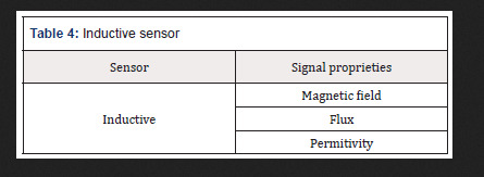
Are Also magnetic sensors sensors Inductive, These sensors create a small magnetic field at its tip and When the metal goes next to it disturbing the magnetic field, the cam sensor to capture this disturbance and sends a signal que can be interpreted by a circuit connected to the sensor (Table 4).
Table 4: Inductive sensor
Mechanic Sensor
These sensors are the ones who have the ability to detect the positions, movements or presence through mechanical means. Among the main applications, we can mention the presence of objects in a Certain place, the detection locks or door openings, and the limit switch sensor is one of the best known. The AIMS limit to Prevent sensing an engine to keep running even after the moving part reach the peak (Table 5).
Table 5: Mechanic Sensor
Optic Sensor
These sensors are also known as photovoltaic and use the propagation of light for its operation. The optical sensor is used to index objects and can also be used to measure the distance at which the object is in relation to the sensor. This type of sensor is used on elevator doors in computer mouse, bar code reader, in more modern vehicle reversing systems and many others (Table 6).
Table 6: Optic Sensor
Thermal sensor
This sensor gives a certain response when subjected to a temperature change. There are various types of thermal sensors and are several applications. The best-known thermal sensor is the thermometer that almost everyone has at home. It is used to measure body temperature. This type of temperature sensor is often used in environments where it is necessary to maintain a certain temperature, such as cold chambers. In this case, the sensor sends a response when it perceives that the temperature is outside of the ideal, and in accordance with this response refrigeration is switched off or activated(Table 7).
Table 7: Thermal sensor
It is important to know that there are specific sensors that fit within these mentioned groups which are the most common. There is a wide range of sensors for the most diverse applications. Following are some examples that may be used in devices embedded in the human body are presented. Indicative prices to be able to have an order of magnitude and make appropriate comparisons are presented [2,3]. The prices presented are based on historic benchmarking and experience of the author.
Proximity and Motion
The Distance ultrasonic sensor is capable of measuring distances of 2cm to 4m with great precision and low price. This module has a ready coupled to a receiver for measurement.
The reflection optical Reflective Phototransistor sensor is coupled in the same device has an infrared sensor (LED) and a phototransistor (receiver). It is specially designed to block light of other bands than the emitter itself, preventing ambient lighting interferences.
The Proximity Sensor Infrared is a photoelectric reflection module which includes an InfraRed (IR) transmitter and an IR receiver. This sensor has a longer range than traditional ones, ranging from 3 to 80 cm with the adjusting screw at the rear of the sensor.
The Absolute Orientation Sensor provides the possible to obtain the absolute position in three axes, useful to set up a project involving virtual reality [4-6].
The PIR Motion Presence Sensor can detect the movement of objects that are in an area up to 7 meters. If something is moving around in this area the alarm pin is activated.
The combined motion sensor on a single chip contains an accelerometer and a gyroscope MEMS type. They have 3-axis accelerometer and 3-axis gyroscope, providing 6 degrees of freedom (6DoF).
The obstacle IR sensor is a circuit composed by a transmitter, an IR receiver, and an IC comparator, which facilitates its connection with Arduino, PIC or Raspberry Pi, since its voltage is 3, 3-5V.
The Reed Magnetic sensor is a switch that works by magnetic field, closing the internal contacts when approaching. When taking the magnet, the contacts open again.
The Encoder speed sensor is used to perform engine speed measurements, pulse count and positioning controller. It can be used with many more drivers and boards such as Arduino, Raspberry Pi and PIC.
The Vibration sensor is designed to detect vibrations. Its applications are numerous but are mainly divided in a useful signal to process and a noise signal to remove. When the intensity is below the preset value (i.e., the value set at the potentiometer), the output is in a high state, otherwise the output is in the low state.
This Hall sensor has high sensitivity based on the Hall effect to measure magnetic fields around them. The magnetic signal is then converted into an electrical signal with high reliability and sensitivity and can be used in a very practical way with an Arduino. Alarms can be used in projects, accountants and other electronic circuits. The Grove magnetic sensor contains a reed switch on the board and can be used to set up alarm systems and proximity sensors based on magnetic fields.
The Vibration sensor Tilt Grove is used to detect movements and make the sign reading in a microcontroller as Arduino, Raspberry or Beaglebone plates and other applications in electronics design. The sensor can be used in monitoring systems and alarms systems, for example.
The gestures and RGB sensor are a plate with a sensor that provides ambient light measurement approach and signals. With Gesture Sensor and RGB it is possible to control a project, a computer design or a robot using only the movement of the hands.
The Distance Laser sensor is different from all the others: it uses a thin and invisible laser light source, and a circuit for detecting how long the light took to reach an object and return to the sensor. It can measure distances of between 30 and 1000mm with high degree of accuracy, has I2C and accepts power from 3 to 5V.
The analog line IR sensor varies the output value according to the amount of infrared light reflected to the sensor. When more light is detected by the IR receiver, the lower the voltage at the analog output.
The accelerometer module is a 12-bit resolution device with low power consumption, perfect for a virtual reality design using microcontrollers.
The Inductive Proximity Sensor is an NPN sensor capable of detecting metal objects up to 4mm away and generate a signal in the sensor output, which can be read by a microcontroller like Arduino.
The IR digital line sensor triggers the digital output according to IR light (infrared) received by the sensor. It is ideal for systems with only I / O available digital pin.
The 3-axis accelerometer has a new version provided now with a built-3.3V voltage regulator.
A Photo Interrupter Breakout Board was developed for easy connection to the component’s microcontroller. For complex projects involving accelerometer, gyroscope and magnetometer it is used an Absolute Orientation Sensor 9-DoF. It can be challenging to extract the necessary data of these sensors and convert them to a 3D world, requiring consolidating the data from these sensors, send them to I2C interface and saving work assemble complex algorithms or perform fine adjustments to extract the data needed.
For even more complex projects a 10DoF Sensor with Barometer, accelerometer, magnetometer and gyroscope is used. This is a powerful sensor IMU (Inertial Measurement Unit) that reaches 10 DOF, with 3-axis gyroscope, 3-axis accelerometer, 3-axis magnetometer and the pressure sensor and temperature.
Expected Price in March 2019 from €1.90 to €267.90
Temperature
The waterproof temperature sensor will allow you to take measurements in wet environments and wet with only one interface of one wire.
The regular temperature and humidity sensor allow temperature readings from 0 to 50° C and humidity 20 to 90%, widely used for projects with Arduino. The wider range temperature and humidity sensor allows temperature readings from -40 to +80° C and humidity from 0 to 100%, and very easy to use Arduino, Raspberry and other microcontrollers because it has only one output digital pin.
The temperature sensor with I2C communication is an accurate sensor, with typical accuracy of ± 0.25 ° C from -40° C to + 125° C + and resolution of 0.0625° C. The Temperature sensor is a sensor easy to use, communicating with the microcontroller via the I2C interface and sending temperature information in digital form, unlike traditional analog sensors. The Sensor Type K thermocouple with measuring range of -50 to 400° C is for use in multimeters and measurement equipment.
The temperature sensor can be a great option when looking for precision, and has easy communication with microcontrollers such as Arduino, PIC, ARM and Raspberry Pi. Widely used for home automation projects or even industrial.
The thermistor is a temperature sensor projects with widely used in microcontrollers, performing measurements in the range of -40 to 125° C based on a 10K Ohm NTC thermistor.
The temperature sensor Grove using a NTC thermistor for measuring the ambient temperature, generating an output voltage which is sent to the microcontroller.
The IR temperature sensor is a high-precision component that detects body temperature or objects by infrared without direct contact with the sensor is needed. It has already been calibrated at the factory and detects temperatures between -40 and 125° C with a precision of 0.5° C, still having multiple configurable user calibration methods.
The temperature and humidity sensor, for Sonoff is capable of measuring temperature and humidity providing data through its digital output. With its plug 4-pole, the sensor is perfectly compatible. The temperature and humidity sensor Son off have a resistive sensor capable of measuring temperature and a capacitive humidity sensor. Data is provided through its digital output. With its plug, the sensor is compatible with Sonoff TH10 / TH16. Sonoff is an affordable WiFi smart switch that provides users with smart home control.
The temperature sensor Waterproof Sonoff allows the functions similar to a thermostat, which can control any equipment according to the temperature.
The Digital Temperature Sensor performs temperature measurements accurately using only one pin of the controller.
The temperature and humidity sensor Grove is a module that contains a sensor on plate being connected to the microcontroller through a standard 4-pin cable Grove. This sensor comes pre-calibrated and is characterized by low power consumption and ease of use.
Expected Price in March 2019 from €2.40 to €80.90
Luminosity
The Brightness 5mm LDR (Light Dependent Resistor) sensor is a component whose resistance varies with the intensity of light. The lighter falls on the component, the lower the resistance. The light sensor can be used in projects with Arduino and other microcontrollers for alarms, home automation, motion, etc.
The Infrared (IR) receiver is useful in electronic projects such as motor control, lighting, alarms and circuits in general. It is user friendly with microcontroller circuit using Arduino, PIC or Raspberry Pi.
The IR Receiver Module is used in electronics design, remote control systems and alarms, for example.
The ambient light sensor module is a simple module to use but very powerful, as it has greater precision than standard modules using LDR (light dependent resistors). The sensor used is NPN phototransistor and the module has an analog output signal that can be read for example by a plate as Arduino. The higher the incidence of light, the higher the value in the output.
The photo Switch is an optical switch that operates with infrared, and on one side have an LED IR emitter establishing a light beam which is detected by the IR receiver on the opposite side. The distance between the transmitter and the receiver is 10mm.
The LDR Light Sensor (Light Dependent Resistor) is designed to detect light and has a digital and analog output that can be connected directly to a microcontroller as the Arduino.
The Infrared Phototransistor LED 5mm receiver is sensitive to infrared light and acts as a receiver of this type of light for use in electronics design as motor control, lighting, alarms and circuits in general. It is easy use with microcontroller circuit using Arduino, PIC or Raspberry Pi.
The UV Sensor is capable of detecting UV solar radiation using a simple chip. It can be easily configured for projects with Arduino to monitor UV Index, analyze UV-A lamps or DIY projects as plant growth analysis.
The Lux Light sensor can determine the amount of light (measured in lux), which is focusing on the sensor, and show that result in a display or trigger microcontroller ports in certain situations to light. Expected Price in March 2019 from €0.90 to €85.90.
Moisture
The humidity sensor Grove is composed of a rod and sends information to the microcontroller according to the humidity level detected by the sensor.
The Hygrometer Humidity Sensor is designed to detect the humidity changes, and when it is dry the sensor output is in the high state and low state when in wet.
The Rain Sensor is used to monitor a variety of weather conditions, but it can be used in liquid drops. When the surface is dry the sensor output is in a high state and when there is a liquid drop the sensor, output is in down state. Expected Price in March 2019 from €9.90 to €13.90.
Temperature and Moisture
The Temperature and Humidity High Precision Sensor and I2C communication with the microcontroller for use in electronics design, weather stations, room temperature control and medical equipment, among others. The sensor has 14-bit resolution and accuracy of 2% humidity and temperature of 0.2° C, providing accurate and reliable information as well as an extremely low power consumption in sleep mode. Expected Price in March 2019 around €65.00.
Chain
The Current Sensor Non-Invasive is an optimal device to measure AC current and is not invasive. It is widely used in projects with home automation Arduino like electrical current meters, protection of AC motors, lighting and others, but the non-invasive propriety is a boost to medical application.
The Current sensor performs current measurements accurately since it uses the Hall effect to detect the magnetic field generated by a current generating at the module output (OUT pin), a proportional voltage 66mV / A.
The DC Current Sensor provides measurements in circuits with DC voltage between 0 and 26V with DC current sensor, a I2C communication module and easy integration with devices such as Arduino, and other I2C interface. Expected Price in March 2019 from €26.90 to €58.90.
Touch
The Touch Sensor Capacitive is a component capable of detecting touches. Its operation is very simple: by touching the indicated region, the output of the sensor is activated. Without touching the sensor, there is no activity on output. It can be used as replacement of a push button.
The flexible sensor is a sensor of Sparkfun whose resistance varies as the sensor is bent. The greater the force applied, the greater the resistance in the sensor output.
The Force Sensor Resistive can make measurements between 100 g and 10 kg, depending on the force applied in the detection area (approximately a 15mm circle). Expected Price in March 2019 from €8.90 to €74.90.
Biometric
The Heart Rate Sensor allows to obtain data very useful when riding an exercise routine, studying daily physical activity or even for teaching purposes. The heart monitor pulse sensor performs reading of the heartbeat using an optical sensor amplified and sends this data to the microcontroller as the Arduino via a single signal pin.
The MyoWare Power Shield is a card designed for use with the Muscular Sensor MyoWare and uses two batteries. The Fingerprint Sensor can be used in projects with high complexity existing in this process.
The Muscular Expander Electrodes MyoWare Sensor allows you to place up to two electrodes directly on the board, being an interesting option for wearable designs (wearables). However, you often need a larger number of electrodes, or more distance between the electrodes and the sensor, and that’s where the Expander MyoWare electrodes. With Expander Electrodes Myoware, you can connectup to three electrodes using the cable MyoWare sensors (not included) connected to the expander through a P2 plug.
The Biomedical Electrode is the component responsible for forwarding to the sensor the electric signal captured during the movement of muscles. It can be connected directly to the Muscular Sensor or cable sensors.
The Sensor Muscular Myoware is a control device with the strength of your muscles. This is a plate designed for use with Arduino and using a sensor electromyography (EMG), which measures the electrical activity of a muscle. Muscular Myoware sensor generates at the output a voltage between 0 volts, and Vs, where Vs is the sensor voltage. The greater muscle activity, the higher the voltage at the output.
The cable Sensor is an accessory to be used in conjunction with the Expander electrodes and allows you to connect up to 3 electrodes in muscle sensor.
The strike sensor and Heartbeat Oximeter is a module consisting of two LEDs and a photodetector circuits that detect heart beats and indirectly measure the amount of oxygen in the blood. The sensor is suitable for projects in the medical field, fitness and wearables, among others. Expected Price in March 2019 from €12.90 to €374.90.
Barometric
The Pressure and temperature sensor have gains in terms of accuracy and power consumption beyond the size 63% smaller, making common their use in mobile and portable devices.
The Pressure and temperature sensor are fully compliant in terms of firmware and interface, including using the same Arduino library. It is a compact sensor with low power consumption (about 0.5μA), being a good choice for projects powered by batteries.
The Air Pressure Sensor measuring range of 0 to 40kPa and using MEMS technology miniaturization of components in a package DIP (dual in-line package). Expected Price in March 2019 around €20.00.
Others
TThe Water Flow Sensor measure water flow for your electronic projects is now no longer a problem with this Water Flow Sensor. It is installed in line with the pipe to measure the amount of water flowing through it, sending PWM pulses to your Arduino and Raspberry Pi for example. Expected Price in March 2019 around €35.00.
The Load Cell Weight Sensor uses the weight sensor load cell together with the module and build its own scale based on Arduino, Raspberry, or other PIC microcontroller. Expected Price in March 2019 around €20.00.
The Water Level Sensor is a liquid level sensor for use in water tanks, reservoirs, tanks and other containers. The level sensor functions as a power switch that can trigger switches, pumps, lamps or send a signal to the microcontroller as the Arduino, Raspberry Pi or Pic. Expected Price in March 2019 around €15.00.
The Color sensor detects the color of objects quickly and accurately with the color recognition sensor. The sensor recognizes light levels RGB (Red, Green and Blue, or red, green and blue) and sends this data to a microcontroller as Arduino, Raspberry, PIC and other models, allowing you to create efficient color detection systems. The Color RGB sensor with IR filter can recognize colors quickly and effectively. Based on chip, this sensor has RGB light sensors which together with the IR filter minimizes the influence of the IR spectrum, such as lights, leaving a much more accurate measurement. Expected Price in March 2019 around €65.00.
The sound sensor Grove is a plate with a microphone that detects the sound system and generates a variable signal at the output according to the intensity of the captured sound. Expected Price in March 2019 around €40.00.
Conclusions
There is a wide range of diferente sensors with diferente applications, advantages and strenghts. Knowing what best suits a real situation is crucial to extend life long. Also, it is important to understand how the sensor communicates the acquired data in order to find the appropriate acquisition and processing signal board.
Read More About this Article: https://biomedgrid.com/fulltext/volume2/a-guide-to-select-sensors-for-biomedical-propose.000583.php
For more about: Journals on Biomedical Science :Biomed Grid
#biomedgrid#Journals on Biomedical Imaging#Journals on Medical Microbiology#Journals on Medical Casereports#Journals on Medical drug and theraputics#Open Access journals on surgery
0 notes
Text
Embedded programming in the Internet of Things
Embedded programming has a long history of making devices do what people need. However, it remains outshined by application programming: when application programmers were embracing high-level object-oriented languages like C++ or Java, or graphical application development environments like MATLAB, embedded programmers were only moving from assembly language to C. Besides, they were always outnumbered by app programmers — simply because now even hobbyists can develop an app using an easy language and upload it to cloud, while embedded programmers need to have profound knowledge of the hardware platform.
With the emergence of the Internet of Things (IoT), the balance can finally change. Now that every thermostat, toaster, watch, and light bulb is equipped with a processor, the market needs more embedded programmers to program these devices, and consequently more simpler tools to allow the programmers to write code without plunging into the hardware.
But first!
What is embedded programming?
According to Technopedia, embedded programming is a specific type of programming that supports the creation of consumer facing or business facing devices that don’t operate on traditional operating systems the way that full-scale laptop computers and mobile devices do. The idea of embedded programming is part of what drives the evolution of the digital appliances and equipment in today’s IT markets.
If explained in simpler words, embedded programming is designing software for small computers that drive devices; essentially, it is the dominant methodology for microcontroller and microcomputer programming used in small facilities-handling devices like thermostats, handheld games or other small devices.
Embedded programming and IoT
From the engineering perspective, the Internet of Things is an embedded microprocessor controlled system connected directly or indirectly to the web. The three pillars of the IoT are therefore embedded programming, network technology and information technology. The embedded system of a device collects data from a sensor and sends it to the cloud using a wifi module — basically, it means that you can turn your embedded device into an IoT device by simply giving it Internet access.
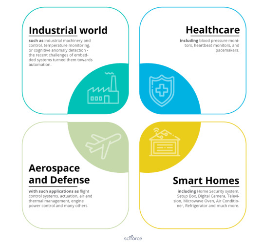
The IoT is everywhere, and so are embedded devices:
Industrial world, such as industrial machinery and control, temperature monitoring, or cognitive anomaly detection — the recent challenges of embedded systems turned them towards automation.
Healthcare, including blood pressure monitors, heartbeat monitors, and pacemakers.
Aerospace and Defense with such applications as flight control systems, actuation, air and thermal management, engine power control and many others.
Smart Homes, including Home Security system, Setup Box, Digital Camera, Television, Microwave Oven, Air Conditioner, Refrigerator and much more.
Embedded systems
Once I’ve read the saying that every complex system in the world can be reduced to two ideas: software and hardware. An embedded system is not an exception: to understand how embedded programming works, we need to understand its hardware and software parts.
Embedded Hardware
The embedded development board is divided into five modules: Processor, Memory, Input devices, Output devices and Bus controllers.
Hardware Components of an Embedded System
Processor
Embedded processors can be broken into two categories: ordinary microprocessors that use separate integrated circuits for memory and peripherals, and microcontrollers that have on-chip peripherals, reducing power consumption, size and cost. Some of the examples of microprocessors include:
Microcontroller (CPU) is an intelligent device that computes the tasks assigned by the user and is used to build small applications with precise calculation.
System on Chip (SoC) comprises a CPU, Peripheral devices (Timers, counters), Communication interfaces (I²C, SPI, UART), and Power Management Circuits on a single IC.
ASIC processor (Application Specific Integrated Circuit) is designed for use for a particular application and owned by a single company.
DSP processor removes the noise and improves signal quality in Audio and Video Applications.
Memory
Data storage and memory management require EEPROM. Some examples of the memories used in embedded systems include Non-Volatile RAM, Volatile RAM, DRAM (Dynamic Random Access Memory), etc.
Input Devices
Input devices, such as sensors, switches, photodiode, optocouplers, etc., take input from the outside world accepting input from the user and responding accordingly.
Output Devices
Output devices, including LCD, LED, seven segment displays, buzzers and relays, are indications or results of input events from outside the microcontroller.
Bus controllers
The bus controller is a communication device that transfers data between the components inside an embedded system. The most widely-spread bus controllers are serial buses (I2C, SPI, SMBus etc.), RS232, RS485 and universal serial bus.
Embedded Software
Embedded software, sometimes called firmware, is written for the device drivers, operating system, and applications, as well as for error handling and debugging.
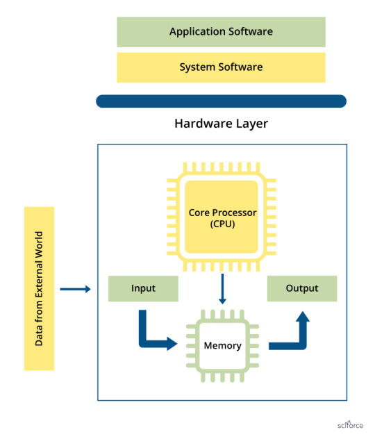
Software Components of an Embedded System
Device Driver
A device driver is a piece of embedded code written for a particular hardware.
Operating System (OS)
Embedded systems have a range of operating systems, including RTOS (Real-time operating systems), mobile embedded, stand-alone and network embedded systems.
Most of the embedded software is now written in two languages, C and C++. There is not much difference between C and C++ in terms of syntax. However, C++ has some additional features, like enhanced security and closeness to real-world applications, while C is considered to be more reliable and showing better performance and directly interacting with the hardware.
Key steps to create an embedded product
Now, knowing the theory, we can prepare ourselves to try embedded programming.
Probably, the best way to start writing software that would directly affect physical objects is to explore such embedded platforms as Arduino, Raspberry Pi, or Particle.
To develop a viable product you should take the following steps:
Step 1. Learn C or C++
And this is where many (me included) stop. However, if you want to write embedded software, you have to learn C/C++ (and maybe eventually Rust).
Step 2. Learn Some Basic Electronics
At least to the extent that you understand what voltage, current, power, resistance, and ohms law are.
Step 3. Get the Basic Equipment
Embedded programmers actually interact with the physical world, so such things as soldering iron, Digital Multi-Meter (DMM), and a hardware debugger/ JTAG adapter (such as an ST-Link, or OLMEX adapter) or a Logic Analyzer would be of help.
Step 4. Choose a Microcontroller and Toolchain
To make your program run, you’ll need a microcontroller to actually run it, a compiler that would compile it for the microcontroller, and other tools to load the program onto your hardware. An example of the compbination of mictocontrollers with a toolchain is the STM32 microcontrollers that are supported by the arm-gcc along with openOCD toolchain.
Step 5. Understand the Datasheets
Before actually sitting down to write the first line of your code, you need to understand the (end user) specifications.
Step 6: Examine the components
Analyze and pick up the components (software and hardware) required to make the product.
Step 7: Design a product
Designing is always the most critical phase of any development cycle. The peculiarity of the embedded programming is that you have to develop the hardware and software parts individually and integrate both.
Step 8: Develop a prototype
A prototype is a sample version created to test the concept which is developed according to the specifications using the selected hardware and software tool.
Step 9: Test the application
Now that the prototype it is possible to run test cases to prove the possible potential of the application.
Step 10: Deploy the application
After testing the application, the result is checked in a real environment to realize the Proof Of Concept — a technique used to validate an idea.
Step 11: Support and Upgrade
If needed, you should be ready to provide support and upgrade the application with new features.

Eleven steps to create an embedded product
And now you are ready to start changing the world — for example, but creating a smart Lego city!
0 notes
Text
Original Post from Talos Security Author:
New 4CAN tool helps identify vulnerabilities in on-board car computers
By Alex DeTrano, Jason Royes, and Matthew Valites.
Executive summary
Modern automobiles contain hundreds of sensors and mechanics that communicate via computers to understand their surrounding environment. Those components provide real-time information to drivers, connect the vehicle to a global network, and in some cases use that telemetry to automatically drive the vehicle. Like any computer, those in vehicles are susceptible to threats, such as vulnerabilities in software, abuse via physical-access, or even allowing remote control of the vehicle, as recently demonstrated by Wired and a DARPA-funded team of researchers.
Allied Market Research estimates the global connected car market to exceed $225 billion by 2025. To help secure this emerging technology, Cisco has dedicated resources for automobile security. The Customer Experience Assessment & Penetration Team (CX APT) represents the integration of experts from the NDS, Neohapsis, and Portcullis acquisitions. This team provides a variety of security assessment and attack simulation services to customers around the globe (more info here). CX APT specializes in identifying vulnerabilities in connected vehicle components.
During a recent engagement, the Connected Vehicle Security practice identified a gap in tooling for automobile security assessments. With ease-of-use, modern car computing requirements, and affordability as motivating factors, the Connected Vehicle Security practice has built and is open-sourcing a hardware tool called “4CAN” with accompanying software, for the benefit of all automobile security researchers. We hope 4CAN will give researchers and car manufacturers the ability to test their on-board computers for potential vulnerabilities, making the vehicles safer and more secure for drivers before they even leave the lot.
What does a car’s network look like?
Before jumping into the 4CAN hardware module itself, let’s start with some automobile basics. For a modern vehicle to operate effectively, its network of hundreds of sensors and computers must communicate with each other. While vehicles and components employ Wi-Fi, Bluetooth, and cellular communication protocols, the backbone of a vehicle’s network is a Controller Area Network (CAN), also referred to as the “CAN bus.”
Access to the CAN bus from a physical perspective is typically via an ODB2 connector, often located on the driver-side lower dash, though it can sometimes also be accessed by removing side mirrors or external lights. Compromising the CAN bus can lead to total control of the vehicle, making it a prime target for pen testers and malicious attackers. Often, attacks against peripheral components such as Wi-Fi or LTE are ultimately an attempt to gain access to the CAN bus.
CAN Bus background
A typical vehicle’s CAN bus is shown below. In a secure configuration, the critical components such as airbags and brakes communicate on separate CAN buses from the non-critical components, such as the radio or interior lights. Pen testers and attackers with access to the CAN bus test for this separation of services looking for insecurely configured vehicles.
The CAN bus is a two-wire multi-master serial bus. Each device connected to the CAN bus is called a “node” or Electronic Control Unit (ECU). When a device sends out a message, or CAN frame, that message is broadcast to the CAN bus and received by every node. When two nodes broadcast a CAN frame at the same time, the arbitration ID, a type of unique node identifier on every CAN frame, determines message priority. The CAN frame with the lower arbitration ID takes priority over the higher arbitration ID.
Electrically, the CAN bus uses differential signaling as a means to reduce noise and interference. There is CAN-HI and a CAN-LO signal, and the two signals are inverse from each other. The bus also has a 120 ohm characteristic bus impedance. When performing a CAN-in-the-middle, the bus must be terminated with a 120 ohm resistor. The image shown below is from Wikipedia, which has an excellent overview of the CAN bus if you’re interested in more detailed information.
Single CAN bus with multiple nodes
The simplest implementation of an automobile’s network uses a single CAN bus. An example with 3 nodes is shown below. All connected nodes will see every CAN message published to the CAN bus. There is no ability to separate critical from non-critical nodes.
Multiple CAN buses with a gateway
A typical vehicle setup has multiple CAN buses combined with a gateway to arbitrate access between the CAN buses. This gateway acts as a firewall and can check CAN IDs to determine if the message should be allowed to traverse CAN buses. In this way, critical ECUs can be isolated from non-critical ECUs.
The vehicles that we have been testing have 4 CAN buses inside, all of which are connected to the gateway. The architecture looks something like this:
The security of each ECU on the bus is partly dependent on the gateway’s ability to segregate traffic. Testing the gateway involves sending and looking for messages allowed to traverse disparate CAN buses. On four-bus systems, this test requires pen testers can access the four buses simultaneously.
Existing solutions
Several devices exist that allow testing of the CAN bus. Most of the devices use the MCP2515 CAN controller, which provides a serial peripheral interface (SPI) to connect with a microcontroller, and a MCP2551 CAN Transceiver or NXP TJA1050 CAN Transceiver, which generates and receives the electrical signals on the physical CAN bus. This table describes some of the CAN hacking solutions currently available on the market.
Each device has its pros and cons, but none completely met our needs of being easy to use, allowing access four buses, and doing so at an affordable price point. Here’s how the currently available devices align with our needs.
In the absence of a compatible device we set out to solve this problem, doing so with the following technical motivators:
Raspberry Pi compatible
Easily enable or disable 120 ohm bus terminating resistors
Natively supported by SocketCAN for easy Linux integration
Inexpensive
Our Solution
We call the solution “4CAN,” and designed it with the following goals in mind:
Validating communication policy for intra-CAN bus communication.
Fuzzing (sending randomized payloads) to components to identify vulnerabilities.
Exploring the CAN commands used to control/interact with the vehicle.
Simplify our testbench setup to keep everything organized and in sync.
Design
George Tarnovsky, a member of CX APT, is the originator or the 4CAN’s design. The Raspberry Pi contains five hardware SPI channels so we decided to use the MCP2515 CAN Controller since it could interface with the Pi via SPI. We added a four-port DIP switch instead of physical jumpers or a solder bridge to easily enable the 120 ohm bus terminating resistors. The MCP2551 CAN transceiver was used as the CAN transceiver.
The high-level design is described in the below schematic.
PCB layout
To be as compatible as possible, we aimed to conform to the Raspberry Pi HAT specification as closely as possible. The HAT spec limits the hardware dimensions, requiring us to use creative solutions to pack all the components on the board. Since we did not include an EEPROM and did not leave a cutout for the camera connector, the module is not HAT compliant per spec. These were conscious design decisions, since we will not be using a camera add-on and do not make use of the EEPROM.
All components are surface mounted, using the smallest component sizes we could find to minimize space on the board. The only exception to using the smallest components is the USB-UART connection. Instead of adding all the components ourselves, we went with a premade board containing all the circuitry. This board sits on top of the 4CAN. A resistor pack further reduces part-count and has a smaller footprint than four individual resistors. Rather than drive all four CAN controllers with individual crystal oscillators, we opted to use just one. This can introduce clock skew, because each component receives the clock in serial, rather than in parallel at the same time. To limit the effect of clock skew, we kept the clock lines as short as possible. In order to keep costs down, we used a 2-layer PCB design. While this limits routing options, the cost is significantly cheaper than a board with more layers. We also added the standard 40-pin GPIO header, so that the remaining GPIO can be used.
The final layout is shown below.
Before and after
Before
In order to test four CAN buses simultaneously, we required three CAN devices. Two TT3201 three-channel CAN Capes attached to Beaglebones, and one CanBerryDual attached to a Raspberry Pi. We also have another Raspberry Pi to remotely control the test vehicle. With this configuration, we can test sending CAN frames between any two combinations of CAN channels. Although this setup works, it is a bit unwieldy, requiring lots of wires making connection tracking and test aggregation difficult.
After
Using 4CAN, the test bench setup is vastly simplified. With a single Raspberry Pi, we can simultaneously test four CAN channels, and since the 4CAN exposes the entire 40-pin GPIO header, we can remotely control the test vehicle.
The simplicity of using 4CAN is easily observable on the physical test bench.
Before 4CAN:
Using 4CAN:
Usage
For the 4CAN to communicate with the Raspberry Pi, the Pi must be configured with four SPI channels enabled and tied to specific GPIO pins. Additionally the Pi’s linux kernel requires additional drivers such as SocketCAN, which implements the CAN device drivers as network interfaces. From a user-space perspective, can-utils loads the SocketCAN drivers and provides capabilities to sniff CAN traffic, send CAN messages, replay captured CAN traffic, implement a CAN gateway to facilitate CAN-in-the-middle, and more.
CAN-in-the-Middle
To determine whether an ECU is sending or receiving a message or to modify CAN traffic in-flight, the 4CAN can be inserted between the CAN bus and an ECU to capture or possibly modify the traffic, to perform a CAN-in-the-Middle (CITM) attack. The required bridging can be enabled by combining can-util’s ‘cangw’ command and a script we have provided.
Sniffing Inter-CAN communication
The 4CAN allows us to test inter-CAN communication by sending a CAN message with a known payload on one CAN bus, and seeing if that same message appears on a different CAN bus. Doing so allows us to learn whether and how the CAN gateway is filtering or modifying messages. In some instances we have observed the CAN ID change for the same message across different buses. We provide a script to facilitate this “transcan” testing.
Tool Release
The 4CAN is available on GitHub here.
#gallery-0-5 { margin: auto; } #gallery-0-5 .gallery-item { float: left; margin-top: 10px; text-align: center; width: 33%; } #gallery-0-5 img { border: 2px solid #cfcfcf; } #gallery-0-5 .gallery-caption { margin-left: 0; } /* see gallery_shortcode() in wp-includes/media.php */
Go to Source Author: Original Post from Talos Security Author: New 4CAN tool helps identify vulnerabilities in on-board car computers…
0 notes
Text
IoT Gateways Market Overview, Growth, Opportunities and Development 2023
The report on the global IoT Gateways market covers historical market trends, current market dynamics, market valuation by segmentation as well as region, country-level analysis for every segment, key player's market share analysis, competitive landscape and supply chain analysis.
Market Highlights:
The global IoT gateways market is predicted to exhibit a 16.9% CAGR from 2018 to 2023 (forecast period) owing to the rise in number of connected devices worldwide. Internet of things (IoT) is a connected ecosystem which disseminated the transfer of data rapidly within local area networks (LANs) and wide area networks (WANs). Miniaturization of processors coupled with its effect on production cost and energy efficiency have paved the way for hardware and software manufacturers.
The rise witnessed in number of connected devices and advacnes in networking topologies are factors likely to augur market growth over the forecast period. The impending need for big data analytics and endpoints to support a complex network architecture in healthcare and other industry verticals are likely to induce the demand for IoT gateways in the forthcoming years. The increasing use of wireless sensors in industrial and commercial applications is predicted to bode well for the IoT gateways market.
Get a Sample report @ https://www.marketresearchfuture.com/sample_request/2956
Major Key Players:
Samsara (U.S.),
Hewlett Packard Enterprise Company (U.S.),
Cisco Systems, Inc. (U.S.),
Huawei Technologies Co. Ltd. (China),
Advantech B+B Smartworx (U.S.),
Bitrective AS (Norway),
Advantech Corporation (Taiwan),
Eurotech (Italy),
Sierra Wireless (Canada),
Volansys Technologies Pvt. Ltd. (U.S.)
According to MRFR, The global IoT gateways market is expected to grow at approx. USD 9 Billion by 2023, at 14% of CAGR between 2017 and 2023.
Industry News:
In March 2019, a leading developer and manufacturer of high-performance System on Module (SOM) solutions and network edge solutions, SolidRun, announced the introduction of SolidSense N6 Edge Gateway which comes with wirepas mesh support.
In February 2019, Farnell element14, a distributor of products for electronic system design, repair, and maintenance, has announced the launch of Avnet SmartEdge Industrial IoT Gateway. It is a low-cost industrial gateway and is powered by Raspberry Pi.
Segmentation:
By type, the global IoT gateways market has been segmented into lightly rugged, rugged, compact, and ultra-compact.
By component, the IoT gateways market has been segmented into field programmable gate array (FPGA), microcontroller units (MCU), sensor, memory card, and others.
By connectivity, the global IoT gateways market has been segmented into Bluetooth, Wi-Fi, ZigBee, Ethernet, cellular, and others.
By applications, the IoT gateways market has been segmented into consumer electronics, building automation, automotive and transportation, wearable devices, healthcare, industrial, and others. The others segment encompasses sub-segments such as oil & gas, aerospace & defense, education, agriculture, BFSI, government, and utilities.
By node, the global IoT gateways market has been segmented into smart watch, smart TV, actuator, camera, RADAR, thermostat, and others.
Regional Analysis:
The global IoT gateways market, by region, has been segmented into North America, Europe, Asia Pacific (APAC), and the Rest of the World (RoW). North America is anticipated to secure the pole position through the assessment period and scale a decent valuation of USD 5,522.5 Mn towards the end of 2025. The region is equipped with advanced IT infrastructure which has led to an establishment of a competitive edge. This, in turn, is likely to expedite the expansion of the IoT gateways market in the foreseeable future.
Europe is expected to exhibit a similar trend as that of North America’s and grow substantially over the next couple of years. The IoT gateways market in the region is poised to strike a CAGR of 16.8% across the assessment period. Asia Pacific is prognosticated to expand at a relatively higher CAGR of 19% during the forecast period. The growth of the industrial sector in the region is presumed to catapult the IoT gateways market on an upward trajectory.
Browse Complete Report @ https://www.marketresearchfuture.com/reports/iot-gateways-market-2956
Intended Audience
Technology investors
Startup companies
Consumer wearable manufacturers
Research/Consultancy firms
Private Equity groups
List of Tables
TABLE 1 LIST OF ASSUMPTIONS
TABLE 2 GLOBAL IOT GATEWAY MARKET, BY GATEWAY TYPE, 2016-2023 (USD MILLION)
TABLE 3 GLOBAL IOT GATEWAY MARKET, BY GATEWAY TYPE, 2016-2023 (K UNITS)
TABLE 4 GLOBAL IOT GATEWAY MARKET, BY COMPONENT, 2016-2023 (USD MILLION)
TABLE 5 GLOBAL IOT GATEWAY MARKET, BY CONNECTIVITY, 2016-2023 (USD MILLION)
TABLE 6 GLOBAL IOT GATEWAY MARKET, BY APPLICATION, 2016-2023 (USD MILLION)
Continued……
List of Figures
FIGURE 1 GLOBAL IOT GATEWAY MARKET: MARKET STRUCTURE
FIGURE 2 RESEARCH PROCESS OF MRFR
FIGURE 3 TOP DOWN & BOTTOM UP APPROACH
FIGURE 4 DROC ANALYSIS OF GLOBAL IOT GATEWAY MARKET
Continued……
About Market Research Future:
At Market Research Future (MRFR), we enable our customers to unravel the complexity of various industries through our Cooked Research Report (CRR), Half-Cooked Research Reports (HCRR), Raw Research Reports (3R), Continuous-Feed Research (CFR), and Market Research & Consulting Services.
MRFR team have supreme objective to provide the optimum quality market research and intelligence services to our clients. Our market research studies by products, services, technologies, applications, end users, and market players for global, regional, and country level market segments, enable our clients to see more, know more, and do more, which help to answer all their most important questions.
Contact:
Market Research Future
+1 646 845 9312
Email: [email protected]
0 notes
Text
Spec ชิปกล้อง
IMX219PQRaspberry Pi for Camera Module V2
https://www.raspberrypi.org/products/camera-module-v2/
The customer will be transferred to the site of the Raspberry Pi Foundation.Diagonal 4.6 mm (Type 1/4.0) 8.08M-Effective Pixel Color CMOS Image Sensor
CMOS Image Sensor for Mobile Products (Smartphones or Tablets) Enabling HD Video Imaging at 180 Frame/s
Sony is releasing "IMX219PQ", Type 1/4.0, approximately 8.08M effective pixels, back-illuminated CMOS image sensor for the growing mobile market. The IMX219PQ satisfies the fulfillment performance of "high sensitivity" and "high frame rate imaging" to meet the demands for high-quality camera applications, and can be easily put on camera fronts of stylish and slim bezel devices achieved by the reduced size. Not only the normal rate of all-8M pixels at full field of view and 30 frame/s, 4 times faster imaging is also possible by 2 × 2 analog binning mode. Also, a LSC function*1 corrects optical unevenness to adjust during the module fabrication process, and contributes to suppressing of system cost. Additionally, combining with a rear-end ISP supporting of BME-HDR*2 enables future scalability of the high-dynamic-range video imaging.
*1: Lens Shading Correction function *2: Two different exposure controls supporting Binning Multiplexed Exposure HDR
High-speed video imaging function
Lens Shading Correction function (LSC)
Supports BME-HDR
Easy to replace the existing product IMX111
* Exmor R is a trademark of Sony Corporation. The Exmor R is a Sony's CMOS image sensor with significantly enhanced imaging characteristics including sensitivity and low noise by changing fundamental structure of ExmorTM pixel adopted column parallel A/D converter to back-illuminated type.
High-Speed Video Imaging Function
Not only the simultaneous still picture and video imaging at 30 frame/s in all pixels (no shutter lag and simultaneous recording), but also 4 times faster imaging became possible by 2 × 2 analog binning mode. This enables HD video recording with 2M pixels at full field of view and 120 frame/s, or 1280 × 720 pixels of 16:9 aspect ratio at 180 frame/s. (Using MIPI 4Lane) Slow-motion recording using this function reproduces dynamic movements into a smooth video (See moving image 1.) in sports scene recording, and sensitive movements or expressions beyond human vision can be captured. (See moving image 2.) The IMX219PQ fulfills camera features and also provides an exciting new experience for all of customers, enabling Sony and the IMX219PQ to contribute to the functional differentiation of smartphone cameras. (See table 1.)
Lens Shading Correction Function
The IMX219PQ has a lens shading correction function with four independent colors. It can be used for not only normal lens shading correction, and also can serve as an individual module adjustment of deviation in the lens assembly process during the module fabrication. Calibration data is written in a built-in OTP during the module inspection to contribute to the short loading time when the camera is turned on. One from three tables can be selected according to color temperature and there exists two-table blending mode for interpolation.
Supports BME-HDR
To support BME-HDR function (See figure 1.) of the existing products IMX134/135*3 that Sony introduced to the market preceding the IMX219PQ, the sensor features a function of the basic technology to set two different exposure conditions. Furthermore, synthesizing from these two different exposure conditions by ISP (Image Signal Processor chip) and applying tone curve optimization enables HDR video recording.
*3: 2012 August 20th News Releases http://www.sony.net/SonyInfo/News/Press/201208/12-107E/
Easy to Replace the Existing Product IMX111
The IMX219PQ retains the equivalent electrical characteristics, spectral sensitivity characteristics, and CRA curve of the existing product IMX111. At the same time, it adds functions to improve picture quality and high-speed imaging, and supports MIPI 2Lane mode in addition to 4Lane mode. Consequently, small firmware modification can replace this latest image sensor functionally enhanced with ease. (See table 2 and figure 2.)
Moving Image 1 Tennis (Serve) Recording at 180 frame/s
*Recorded with a sample module, the actual picture quality of the image sensor might be different.
Moving Image 2 Dog Agility Slalom Recording at 180 frame/s
*Recorded with a sample module, the actual picture quality of the image sensor might be different.
Figure 1 About BME HDR
An image processing technology for subjects with high contrast. It synthesizes different exposure conditions into an image so that both bright and dark data can be seen at the same time.
Figure 2 Target CRA (Compared with the IMX111)
Table 1 Imaging Size and Frame RateSizeFrame rateRemarks
3280 × 2464 (full size)30 frame/s
1640 × 1232 (1/4 size)120 frame/s
1408 × 792 (full FOV for 1280 x 720 HD video)180 frame/s*High-sensitivity mode
1280 × 720 (720 at HD, cropping)198 frame/s*High-sensitivity mode
960 × 540 (QHD, cropping)240 frame/s*High-sensitivity mode
Table 2 Device ComparisonItemIMX111PQIMX219PQ
Image sizeDiagonal 4.60 mm (Type 1/4.0)Diagonal 4.60 mm (Type 1/4.0)
Total number of pixels3296 (H) x 2512 (V)
Approx. 8.28M pixels3296 (H) x 2512 (V)
Approx. 8.28M pixels
Number of active pixels3280 (H) x 2464 (V)
Approx. 8.08M pixels3280 (H) x 2464 (V)
Approx. 8.08M pixels
Fabrication processBack-illuminated processBack-illuminated process
Unit cell size1.12 µm (H) × 1.12 µm (V)1.12 µm (H) × 1.12 µm (V)
Output formatMIPI 2, 1 LaneMIPI 4, 2 Lane
Control communication interfaceI
2
CI
2
C fast mode plus (1 MHz)
Power supply
specificationsAnalog2.7 +0.2/-0.1 V2.8 ± 0.2 V
Digital1.2 ± 0.1 V1.2 +0.1/-0.12 V
I/O1.8 ± 0.1 V1.8 ± 0.18 V
PGA41.7 dB (Max.)44.56 dB (Max.)
Input clock frequency6 to 60 MHz6 to 27 MHz
Signal processing function within sensor
Spot pixel compensation✔✔
Moving picture specifications720p60 frame/s
540M bps/Lane × 2 Lane180 frame/s
726M bps/Lane × 4 Lane
1080p30 frame/s
405M bps/Lane × 2 Lane60 frame/s
726M bps/lane × 4 Lane
*Sony reserves the right to change products and specifications without prior notice.
VOICE
Compared to existing products, we have developed IMX219PQ to achieve "more appealing functions for more users" and launched it on the mobile market. We operate technical support centers in each region (three cities in China, Taiwan, US, and UK) besides Japan. Contact the following office for data sheets, application notes and other download services from the Sony website.
http://www.sony-semicon.co.jp/business/base_en.html
We will collaborate with more AP makers to enhance customer satisfaction and will continue to expand the product lineup and fulfill the support organization so that we can offer ease of use with this product.
Application Engineer: Mr.Nomura , Mr.Sasaki , Mr.Kishimoto
0 notes
Text
Raspberry Pi Alternatives – 17 competitors
Raspberry Pi has become the next big thing.
Both Raspberry Pi and Raspberry Pi 2 have created great, intense interest in single-board computers.
Simple portable, and affordable, they bring a lot to the table.
However, maybe you don’t want a Pi. You might be looking for something that fulfills the same functions but is a bit different. There are a lot of alternatives to Raspberry Pi out there.
First, let’s look at what makes the Raspberry Pi unique and some of the reason you might want to look for a Raspberry Pit alternative. The Raspberry Pi Model B boasts a 900 MHz processor, a full HDMI port, 1 GB of RAM, a camera interface, a display interface, a micro SD card slot, and a GPU. It can run both Windows 10 and Linux. All this will run you around $35.
You can still pick up the first gen Raspberry Pi, but it has noticeably worse specs than the Raspberry Pi 2. The original has a 700 MHz processor, either 256 or 512 RAM, and only either one or two USB ports. A few of the very earliest models do not even have Ethernet ports, so there’s no alternative to using Wi-Fi. The Raspberry Pi 2 is a clear improvement.
All these seem like serious selling points for the Raspberry Pi, but there are issues. A lot of computers like Raspberry Pi provide more power, with faster processors, better GPUs, more RAM, and more connectors. They can even offer services no model of Raspberry Pi offers right now.
You can find that some of the Raspberry Pi competitors offer features like built in Wi-Fi, gigabit Ethernet, and occasionally a decent amount of onboard storage. The barest, most stripped down version of a computer can work for a lot of people, but you’ll find it has a lot of limits, especially for complex projects.
Arduino Industrial 101
Arduino Industrial 101 is an Evaluation board for the Arduino 101 LGA module. It supports Linux distribution, which is based on an OpenWRT named LininoOS. The ATmega32u4 microcontroller is fully integrated in the baseboard.
This computer’s board has built in Wi-Fi, utilizing IEEE 802.11b/g/n operations up to 150Mbps 1×1 2.4 GHz), 4 Analog inputs, 1 USB, 3 GPIOs (2 of which can be used as PWM Outputs), and 1 Ethernet signal on pin header. It also has a built in DC/DC converter. Use the assembly guide, then simply connect your board to a computer using a micro USB cable to get going.
Please note that in some countries, it is against the law to sell Wi-FI enabled devices without government permission. Some local distributors disable Wi-Fi functionality while awaiting certification.
Banana Pi
Meant to be an open source, Banana Pi is touted as a close alternative to Raspberry Pi. It is manufactured in Chine and is noticeably, but not very, physically larger than the Raspberry Pi. It has assorted OS options available, including Lubuntu, Fedora, Arch Linux, Free BSD, a Debian variant named Bananian, Android 4.2, and Android 4.4.
You can use the Raspbian OS, but the CPU will compile it with all the requirements of the Debian Armhf port.
The hardware offers up a lot of similarities to Raspberry Pi. There are several variants to the Banan Pi boards, but these are the specs on the most current one, the Banana Pi M64: a 1.2 Ghz Quad-Core ARM Cortex A53 64-Bit Processor, 2GB of RAM, and 8GB eMMC.
It comes with built in Wi-Fi and Bluetooth. There are 2 USB A 2.0 ports, a USB OTG port, an HDMI port, an audio jack, and a Dc power port. A few models also offer SATA 2.0 port support. It’s truly standout feature is its storage capacity. You can use an SD card with a max of 64 GB, and get a max of 2 TB via the SATA port.
The versatile board makes this a good choice for anyone who wants to try building their own computers. It’s not as cheap as some Raspberry Pi competitors, but it is hardly expensive.
BBC micro:bit
This tiny computer is meant for schools. More than a million of them were given away to school children in the UK. They’ve since started to be handed out globally. A non-profit named Micro Bit Educational Foundation now manages this effort.
The BBC micro:bit is powered by a 32-bit ARM Cortex. It has a 5x% LED matrix, with 25 programmable red LEDs for a display. There are a few push buttons allowing for interactions for games and other programs. It also has a Magnetometer, Accelerometer, and Bluetooth antenna.
Beaglebone Black
Beaglebone Black is designed to be easy and simple to set up and start using; the website promises users can “boot Linux in under 10 seconds and get started on development in less than 5 minutes with just a single USB cable.”
Beaglebone Black is powered with TI AM335x 1GHz ARM® Cortex-A8, capable of supporting Linix Minix, Sybian, Free BSD, Open BSD, and RISC OS. It’s a great platform for development work. Project Rowboat enables Android on this platform.
This a very compact device, measuring 75mm x 75mm, and is very portable. It has an HDMI and an S-Video port. The GPU is powers by Imagination Technologies, allowing 2D and 3D rendering. Beaglebone Black comes with 4GB 8-bit eMMC on-board flash storage and 512MB DDR3 RAM.
This a very cheap platform, but it packs a lot of bang for the buck. Its creators developed it for coders and developers working with Linux. It’s a good alternative to Raspberry Pi, with a few more added features and a very easy setup that make it stand out.
C.H.I.P.
This is a very tiny computer, the size of a credit card (60mm long) hailing from Next Thing Co. It runs $9, much cheaper than Raspberry Pi and the Raspberry Pi alternatives. It is more powerful than all the first gen models of Raspberry Pi.
C.H.I.P. has Bluetooth and Wi-Fi. No reason to be worried about sacrificing its single USB port for an internet or device connection. It offers a 1 GHz R8 ARM processor, 512MB of RAM, and 4GB of flash storage. It is a very interesting little computer, especially with its wireless capabilities and on-board storage. It started shipping in December of 2016.
cloudBit
This platform is probably the easiest way to create internet connected devices. It requires no wiring, soldering, or programming. Its IFTTT support gives it the ability to connect with any web service there is, including Twitter. It can even connect with hardware, like Philips HUE or NEST.
Intel Galileo Gen 2
Intel decided to enter this market with their own Raspberry Pi competitor, an updated version of their earlier Intel Galileo single board PC. This was not a competitive board, offering less than others like Raspberry Pi, but the Intel Galileo Gen 2 holds its own.
It is powered by Intel’s Quark Application processor, with 32-bit Quark SoC X1000 processor and a clock speed of up to 400 MHz.
The Galileo Gen 2 has software and hardware compatibility with the Arduino environment. Using Pentium architecture has ensured both the software and the hardware is compatible not just with Arduino, but also its numerous shields.
You can develop a project with rather serious hardware interfacing requirements and decent computer power. The Galileo Gen 2 also offers some I/O slots and expansion ports, so you can modify it if you want or need to.
This is a nice development unit for anyone interested in working with Intel-based Quark architecture, an old familiar for a lot of users. It lacks the video and audio output offered by Raspberry Pi, so know what you’re looking for if you’re thinking about buying this platform.
MinnowBoard MAX
MinnowBoard offers two versions: the $140 version and the $100 version. The $140 version offers 2 GB of RAM, while the cheaper version only offers half that at 1 GB. Both have include a 1.33 GHz dual-core processor, an Intel graphics with HDMI out, a micro SD port, two USB ports, a SATA2 hard drive connection, and an Ethernet connection.
You can get more for less, but there are expansions planned, fittingly known as ‘lures’. These look to be useful for developers in particular. It’s hard drive connection is a good point, too, as Raspberry Pi and very few of the alternatives offer that.
NanoPi 2 Fire
This unit runs only $22.99. It is powered by an A9 quad-core SoC, with 1GB of DDR3 RAM. No Wi-Fi or Bluetooth here; The NanoPi 2 Fire connects to the web via Ethernet and/or its USB 2.0 port. It also includes a power management unit to support software sleep, wake, and power-off functions. It can run both Android and Debian Linux.
NanoPC-T1
This is a very low-cost platform and an excellent way to break into microcomputing. It has a 1.5 GHz Samsung quad-core processor, 1 GB of RAM, 8 GB of onboard storage, an HDMI port, an audio port, three USB ports, an ethernet port, and an SD card slot. It supports Android and Linux. It can manage just about any simple project.
You can also add on an adapter board, a standard or hi-def camera, and an LCD touchscreen. You can do a lot with these options, making things like touchscreen games or home security systems. NanoPC, the company behind the NanoPC-T1, sells lots of other accessories and modules, including a $25 Wi-Fi module.
ODROID-XU4
This is the flagship product for Hardkenel, the development company behind this platform. It’s smaller and more powerful than their earlier Odroid XU3.
It uses ARM® big.LITTLE™ technology, which combines ARM CPU cores to maximize efficiency and increase parallel processing performance at much lower power consumption. It is powered by Samsung Exynos5422 Cortex™-A15 2 Ghz and Cortex™-A7 Octa core CPUs.
It also has 2 G.B LPDDR3 RAM, 2x USB 3.0 support, and Gigabit Ethernet support. It can run Android KitKat, Android Lollipop, and Ubuntu. It is also backward compatible with all the XU3’s software. It does not have a SATA port, so bear that in mind.
This a very powerful single-board computer. It performs two to four times faster than Raspberry Pi 3. The fan can make a very loud humming noise when the CPU is high. Take a look at it if you’re looking for a high end single-board PC.
Orange Pi PC2
This is a solid option among Raspberry Pi alternatives. It might be best to call it a clone, in fact. It offers specs similar to the Raspberry Pi, including Ethernet, three USB ports, USB OTG, 1GB of RAM and a quad-core 64-bit Cortex-A53 processor, and a GPU. It has a number of OS options: Banana Pi, Debian, Raspbian, Android, and Ubuntu.
Parallella
This is a small computer, the size of a credit card, with a lot of kick. It’s based on the Epiphany multi-core chips from Adapteva. It starts at $99. You can use it as a standalone computer or as a component in a parallel server cluster.
pcDuino4 Set-Top Box
This platform is designed to be a media center device, one of the more common uses of Raspberry Pi. It has a 1.6 GHz quad-core processor, Mali GPU, 1 GB of RAM (shared with the GPU), 8 GB of onboard storage, and a Wi-Fi module.
It doesn’t offer a lot of features, though as a part of its design as a media center, you can put out both HD and 4K video through its HDMI port, as well as use its AV output for older TVs. It also offers an IR receiver remote. The enclosure in included. It’s pretty cheap, but it’s a good option for anyone wanting to use a single board computer as a media center.
Radxa Rock2 Square
The Radxa Rock2 has a quad-core processor, 2.5″ SATA hard drive compatibility, Bluetooth 4.0, HDMI port, ethernet port, headphone port, IR receiver, and SD card port. You can opt to have either 2 GB or 4 GB of RAM, as well as either 16 GB or 32 GB of solid-state storage.
You can also add in a 3.5” hard drive with a few modifications for a useful upgrade. The Rock2 is based on Android, but I can also run the Firefox OS and Linux. It’s a very powerful and versatile platform, far more so than the Raspberry Pi.
UDOO Dual Basic
This is the smallest available unit on the UDOO lineup. It offers a 1 GHz processor, 1 GB of RAM, both 2D and 3D graphics accelerators, HDMI output, two micro-USB ports, two USB-A ports, an onboard micro SD card reader, and both audio and mic ports. There are also Arduino compatible pinouts.
This is one of the best deals, price wise, among the UDOO boards. Be mindful, however, that the UDOO Neo is coming out soon, which boasts Bluetooth, Wi-Fi, and a 9-axis sensor.
VoCore
This is an open hardware platform. It runs on Open Wrt/LEDE and has a plethora of features, including USB ports, Wi-Fi, UART, and over 20 GPIOS—all in a one inch square. I can help you create a smart house, a very small router, or a study embedded system.
You willg et the full package when you buy VoCore: its hardware, schematic, circuit board, bill of materials, full source code (not including the boot loader), operating system, and applications. You control it entirely.
Conclusion
There are plenty of alternatives to Raspberry Pi. Some are powerhouses that make the Pi systems look like kittens, while others are tailored to very specific functions. Take a look at them base don out overviews if you find anything that serves your needs.
from Web Development & Designing http://www.designyourway.net/blog/tech/raspberry-pi-alternatives-competitors/
0 notes
Text
ISS Daily Summary Report – 5/02/2017
OsteoOmics: The crew thawed a BioCell and injected it into growth media in the Microgravity Science Glovebox (MSG). After all six BioCells are processed they are put in BioCell Habitat 1 which is placed in the Space Automated Bioproduct Lab (SABL). Beginning with the media injection, subsequent BioCell operations are performed inside the MSG. Later in the day the crew removed a media kit from a Microgravity Experiment Research Locker / INcubator (MERLIN) and inserted it into an ambient Cargo Transfer Bag for the next day’s operations. This is the first of four weeks of OsteoOmics operations. A different BioCell Habitat, each containing six BioCells in media, is used each week. Crewmembers experience bone loss in orbit, stemming from the lack of gravity acting on their bones. OsteoOmics investigates the molecular mechanisms that dictate this bone loss by examining osteoblasts which form bone, and osteoclasts, which dissolve bone. Improved understanding of these mechanisms could lead to more effective countermeasures to prevent bone loss during space missions and in a wide range of disorders on Earth. This may lead to better preventative care or therapeutic treatments for people suffering bone loss as a result of bone diseases like osteopenia and osteoporosis, or for patients on prolonged bed rest. Fluidics: The crew assembled Fluidics hardware and installed and configured it on seat-tracks in the Columbus module. They then started the first science run. Following completion of that run the crew replaced fluid tanks and performed the second run. Fluidics is a fluid mechanics experiment with two main objectives: a Slosh Study to investigate fluid behavior under microgravity during satellite maneuvers, and a Wave Turbulence Study to investigate the impact of capillary effect on wave turbulence without being masked by the effect of gravity. Two tanks with different filling rations (50% and 75%) for Slosh and one tank with water for Wave Turbulence are used. Radiation Dosimetry Inside ISS-Neutron (RaDI-N) Retrieval: The crew retrieved all 8 of the Space Bubble Detectors that were deployed last week in the Node 2 module for the RaDI-N experiment and handed them over to the Russian crewmember to be processed in the Bubble Reader. This Canadian Space Agency (CSA) RaDI-N investigation measures neutron radiation levels while onboard the ISS. Bubble detectors are used as neutron monitors designed to only detect neutrons and ignore all other radiation. Dose Tracker: The crew completed a weekly medication tracking entry in the Dose Tracker application that runs on an iPad. Dose Tracker documents the medication usage of crewmembers before and during their missions by capturing data regarding medication use during spaceflight, including side effect qualities, frequencies and severities. The investigation is expected to provide anecdotal evidence of medication effectiveness during flight and any unusual side effects experienced. It is also expected that specific, near-real-time questioning about symptom relief and side effects will provide the data required to establish whether spaceflight-associated alterations in pharmacokinetics or pharmacodynamics is occurring during missions. Extravehicular Activity (EVA) Preparations: In preparation for the EXPRESS Pallet Controller Assembly (ExPCA) EVA currently planned for May 12, the crew configured computers to record Extravehicular Mobility Units (EMUs) 3006 and 3008 operating data which ground teams will use for detailed analysis of the suits’ function. The crew also performed loop scrubs on the EMUs and filled the empty Liquid Cooling Venting Garments (LCVGs) with water which will provide cooling for the crew members during the EVA. Mobile Servicing System (MSS) Operations: Yesterday evening Robotics Ground Controllers powered up the MSS and maneuvered the Special Purpose Dexterous Manipulator (SPDM) Body and Arm 2 as required to stow Robot Micro Conical Tool #2 (RMCT2) in the SPDM Tool Holder Assembly (THA). They then configured the SPDM for the start of the Main Bus Switching Unit #2 (MBSU2) R&R and maneuvered the Space Station Robotic Manipulator System (SSRMS) into position to perform a survey of MBSU2 using SPDM and SSRMS cameras. Finally, Controllers maneuvered the SSRMS to the start position for the MBSU2 R&R which is scheduled on May 4. Today’s Planned Activities All activities were completed unless otherwise noted. Virus Definition File Update on Auxiliary Computer System (ВКС) Laptops VIZIR. СКПИ Battery Charge Extravehicular Mobility Unit (EMU) High Speed Data Initiation OsteoOmics MSG Operations Regeneration of БМП Ф1 Micropurification Cartridge (start) Charging Sony PMW-EX1R camcorder battery (start) OsteoOmics Thaw Kit Retrieval Extravehicular Mobility Unit (EMU) Cooling Loop Maintenance Scrub Initiation Recharging Soyuz 735 Samsung PC Battery (if charge level is below 80%) OsteoOmics Thaw Bag Retrieval OsteoOmics MELFI Retrieval Crew time for ISS adaptation and orientation OsteoOmics BioCell Thaw Operations Initiate water transfer from CWC-I to ЕДВ No.1237 Removal of Battery Module No.2 ПТАБ-1М (pos.А302), preparation Terminate water transfer from CWC-I to ЕДВ Extravehicular Mobility Unit (EMU) High Speed Data Verification Steps PROFILAKTIKA-2. Preparation for the Experiment Ops PROFILAKTIKA-2. Operator Assistance in Preparation for the Experiment Extravehicular Mobility Unit (EMU) Post Scrub Cooling Loop Water (H2O) Sample Extravehicular Mobility Unit (EMU) Cooling Loop Maintenance Scrub Reconfiguration PROFILAKTIKA-2. Experiment Ops on БД-2 Treadmill Terminate Soyuz 735 Samsung PC Battery Charge (as necessary) Charging Sony PMW-EX1R camcorder battery (end) VIZIR. End СКПИ battery charge Extravehicular Mobility Unit (EMU) Liquid Cooling Ventilation Garment (LVCG) Water Fill PROFILAKTIKA-2. Close-out ops (Operator) OsteoOmics BioCell Habitat Cleanup Photo/TV Camcorder Setup Verification Extravehicular Mobility Unit Fan Dryout Crew time for ISS adaptation and orientation Extravehicular Mobility Unit (EMU) Full Water Tank Dump and Fill TOCA Water Recovery System (WRS) Sample Analysis Search for missing СтА accessories (hatch tool, electric plugs, connector caps) in SM ПрК CASKAD. Manual Mixing in Bioreactor CONSTANTA-2. Removal of Cassette from ТБУ-В and setup on panel for 1-hour warmup Fluidics hardware installation and science run start Filling (separation) of ЕДВ (КОВ) for Elektron or ЕДВ-СВ. CONSTANTA-2. Preparation and Execution 3. Tagup with specialists EVA Extravehicular Mobility Unit (EMU) Cooling Loop Scrub Deconfiguration OsteoOmics BioCell Split Habitability Human Factors Directed Observations – Subject Emergency Cue Card Trash СОЖ Maintenance Extravehicular Mobility Unit (EMU) Conductivity Test Extravehicular Mobility Unit (EMU) High Speed Data Deconfig SPRINT PI Conference Photo/TV Camcorder […] from NASA https://go.nasa.gov/2oXSn2E via IFTTT | Java Wisata
0 notes
Text
Power Management IC Market Growth Rate Research Report by Forecast 2023
Market Research Future published a research report on “Power Management IC Market Research Report - Global Industry Forecast To 2023” – Market Analysis, Scope, Stake, Progress, Trends and Forecast to 2023.
Market Insight
The global power management IC market is cementing its foothold due owing to the traction generated by information and communication sector globally, thus expecting an exponential expansion with 8.8% CAGR during the forecast period (2018-2023), declares Market Research Future (MRFR). The valuation of the market is also recorded as USD 38,388.9 Mn to achieve in the same period. The study encompasses several thriving factors and drivers that are contributing to the market’s growth in the present as well as in the future. PMIC includes a broad range of chips and can be integrated into battery-operated devices, such as mobile phones and portable media players.
Market Drivers & Trends
According to the report published by MRFR, the rising miniaturing trend in the electronics industry has a massive impact which is the chief Power Management IC Market influencer. Apart from the information and communication sector, it is also getting popular with consumer electronics sector being a significant end-user of PMIC, which can be a great boon for the global power management IC market.
On the other hand, the factors such as the need for efficient power, high density and design flexibility of power modules are supporting the market growth inevitably. At the same time, the growth of silicon-carbide (SiC) and gallium nitride (GaN) are also likely to open new growth opportunities for market players going forward and acquire more valuation. On the flip side, the factor of development issues in multi-power domain SoCs can limit the adoption rate of power management IC in the coming years, thus restricting the market growth in the forecast period.
Get Free Sample Report @ https://www.marketresearchfuture.com/sample_request/5038
Key Players
Some of the key players in the market are Texas Instruments Inc. (U.S.), ON Semiconductor Corp. (U.S.), Analog Devices, Inc. (U.S.), Dialog Semiconductor PLC (U.K.), Maxim Integrated Products, Inc. (U.S.), STMicroelectronics N.V. (Switzerland), and Linear Technology Corp. (U.S.), Renesas Electronics Corporation (Japan), Toshiba Corporation (Japan), among others.
Market Segmentation:
MRFR’s study includes a detailed segmental analysis of global power management IC market based on product and application.
By the mode of product, the market has included various segments such as integrated ASSP power management IC, motor control IC and voltage regulators. The integrated ASSP power management segment is further sub-segmented into battery management IC, LED drivers ICs, PFC controllers hot-swap controllers, wireless charging ICs, energy management ICs, PoE controllers. The segment is likely to remain extremely attractive during the estimation period and post a CAGR of 9.3% as there was an uptick in the adoption of integrated ASSP power management IC for its high-performance characteristics.
By the mode of application, the market included consumer and wearable electronics, telecom and networking and automotive. The consumer and wearable electronics segment, therefore, stood at a valuation of USD 9,275.6 Mn in 2017 and is now expected to remain highly attractive in 2019 and would expand at a striking pace over the next couple of years. Sales of consumer and wearable electronics such as smartwatches, cameras, smartphones, TVs, laptops and fitness bands have consistently grown in recent years, which have been driving the segment’s growth.
Detailed Regional Analysis:
According to regional analysis, the study of global power management IC market has covered the main regions of North America, Europe, Asia Pacific, Latin South America and the Middle East & Africa (MEA).
Among these, in 2017, Asia Pacific (APAC) held for the largest market share in terms of value and is now anticipated to witness a CAGR of 8.9% in the forecast period. APAC region is led by China that offers lucrative market avenues and is the go-to destination for all the market players related to the market. Economic surge and incidence of a massive semiconductor industry are some of the key factors boosting the market share in the region. Furthermore, the incidence of a large number of wafer fabrication manufacturers is also contributing the market growth in APAC. China makes a noteworthy contribution to the global semiconductor component supply, which characterizes its strong position in the market.
In North America region, the power management integrated circuit market is increasing at an extensive rate, as the Brazilian government is doing hard work to attract prominent companies to invest in their production plans of semiconductor plants. Furthermore, the companies involved in these plans will be exempted from federal taxes, such as ISS, COFINS, and PIS. Additionally, this region is also witnessing the intensifying demand for energy-efficient LED lights, portable devices, and electric vehicles, which will likely to drive the power management IC market in the future.
The European region is likely to drive the market over the forecasted period due to the rising number of R&D activities witnessed in the automation sector and portable devices for achieving more energy efficiency. Even the manufacturers in the European region are developing customized solutions in intergraded circuits to meet the developing demand in various industrial applications.
Get complete Report @ https://www.marketresearchfuture.com/reports/power-management-ic-market-5038
TABLE OF CONTENTS
LIST OF TABLES
Table 1 Market Synopsis
Table 2 List Of Assumptions
Table 3 Global Power Management Integrated Circuit (Pmic) Market, By Product, 2017–2023 (Usd Million)
Table 4 Global Power Management Integrated Circuit (Pmic) Market, By Application, 2017–2023 (Usd Million)
Continued…
Get New Updates @ https://www.linkedin.com/company/ict-mrfr
About Us:
At Market Research Future (MRFR), we enable our customers to unravel the complexity of various industries through our Cooked Research Report (CRR), Half-Cooked Research Reports (HCRR), Raw Research Reports (3R), Continuous-Feed Research (CFR), and Market Research & Consulting Services.
Media Contact:
Market Research Future
Office No. 528, Amanora Chambers
Magarpatta Road, Hadapsar,
Pune - 411028
Maharashtra, India
+1 646 845 9312
Email: [email protected]
0 notes
Link
OsteoOmics: The crew thawed a BioCell and injected it into growth media in the Microgravity Science Glovebox (MSG). After all six BioCells are processed they are put in BioCell Habitat 1 which is placed in the Space Automated Bioproduct Lab (SABL). Beginning with the media injection, subsequent BioCell operations are performed inside the MSG. Later in the day the crew removed a media kit from a Microgravity Experiment Research Locker / INcubator (MERLIN) and inserted it into an ambient Cargo Transfer Bag for the next day’s operations. This is the first of four weeks of OsteoOmics operations. A different BioCell Habitat, each containing six BioCells in media, is used each week. Crewmembers experience bone loss in orbit, stemming from the lack of gravity acting on their bones. OsteoOmics investigates the molecular mechanisms that dictate this bone loss by examining osteoblasts which form bone, and osteoclasts, which dissolve bone. Improved understanding of these mechanisms could lead to more effective countermeasures to prevent bone loss during space missions and in a wide range of disorders on Earth. This may lead to better preventative care or therapeutic treatments for people suffering bone loss as a result of bone diseases like osteopenia and osteoporosis, or for patients on prolonged bed rest. Fluidics: The crew assembled Fluidics hardware and installed and configured it on seat-tracks in the Columbus module. They then started the first science run. Following completion of that run the crew replaced fluid tanks and performed the second run. Fluidics is a fluid mechanics experiment with two main objectives: a Slosh Study to investigate fluid behavior under microgravity during satellite maneuvers, and a Wave Turbulence Study to investigate the impact of capillary effect on wave turbulence without being masked by the effect of gravity. Two tanks with different filling rations (50% and 75%) for Slosh and one tank with water for Wave Turbulence are used. Radiation Dosimetry Inside ISS-Neutron (RaDI-N) Retrieval: The crew retrieved all 8 of the Space Bubble Detectors that were deployed last week in the Node 2 module for the RaDI-N experiment and handed them over to the Russian crewmember to be processed in the Bubble Reader. This Canadian Space Agency (CSA) RaDI-N investigation measures neutron radiation levels while onboard the ISS. Bubble detectors are used as neutron monitors designed to only detect neutrons and ignore all other radiation. Dose Tracker: The crew completed a weekly medication tracking entry in the Dose Tracker application that runs on an iPad. Dose Tracker documents the medication usage of crewmembers before and during their missions by capturing data regarding medication use during spaceflight, including side effect qualities, frequencies and severities. The investigation is expected to provide anecdotal evidence of medication effectiveness during flight and any unusual side effects experienced. It is also expected that specific, near-real-time questioning about symptom relief and side effects will provide the data required to establish whether spaceflight-associated alterations in pharmacokinetics or pharmacodynamics is occurring during missions. Extravehicular Activity (EVA) Preparations: In preparation for the EXPRESS Pallet Controller Assembly (ExPCA) EVA currently planned for May 12, the crew configured computers to record Extravehicular Mobility Units (EMUs) 3006 and 3008 operating data which ground teams will use for detailed analysis of the suits’ function. The crew also performed loop scrubs on the EMUs and filled the empty Liquid Cooling Venting Garments (LCVGs) with water which will provide cooling for the crew members during the EVA. Mobile Servicing System (MSS) Operations: Yesterday evening Robotics Ground Controllers powered up the MSS and maneuvered the Special Purpose Dexterous Manipulator (SPDM) Body and Arm 2 as required to stow Robot Micro Conical Tool #2 (RMCT2) in the SPDM Tool Holder Assembly (THA). They then configured the SPDM for the start of the Main Bus Switching Unit #2 (MBSU2) R&R and maneuvered the Space Station Robotic Manipulator System (SSRMS) into position to perform a survey of MBSU2 using SPDM and SSRMS cameras. Finally, Controllers maneuvered the SSRMS to the start position for the MBSU2 R&R which is scheduled on May 4. Today’s Planned Activities All activities were completed unless otherwise noted. Virus Definition File Update on Auxiliary Computer System (ВКС) Laptops VIZIR. СКПИ Battery Charge Extravehicular Mobility Unit (EMU) High Speed Data Initiation OsteoOmics MSG Operations Regeneration of БМП Ф1 Micropurification Cartridge (start) Charging Sony PMW-EX1R camcorder battery (start) OsteoOmics Thaw Kit Retrieval Extravehicular Mobility Unit (EMU) Cooling Loop Maintenance Scrub Initiation Recharging Soyuz 735 Samsung PC Battery (if charge level is below 80%) OsteoOmics Thaw Bag Retrieval OsteoOmics MELFI Retrieval Crew time for ISS adaptation and orientation OsteoOmics BioCell Thaw Operations Initiate water transfer from CWC-I to ЕДВ No.1237 Removal of Battery Module No.2 ПТАБ-1М (pos.А302), preparation Terminate water transfer from CWC-I to ЕДВ Extravehicular Mobility Unit (EMU) High Speed Data Verification Steps PROFILAKTIKA-2. Preparation for the Experiment Ops PROFILAKTIKA-2. Operator Assistance in Preparation for the Experiment Extravehicular Mobility Unit (EMU) Post Scrub Cooling Loop Water (H2O) Sample Extravehicular Mobility Unit (EMU) Cooling Loop Maintenance Scrub Reconfiguration PROFILAKTIKA-2. Experiment Ops on БД-2 Treadmill Terminate Soyuz 735 Samsung PC Battery Charge (as necessary) Charging Sony PMW-EX1R camcorder battery (end) VIZIR. End СКПИ battery charge Extravehicular Mobility Unit (EMU) Liquid Cooling Ventilation Garment (LVCG) Water Fill PROFILAKTIKA-2. Close-out ops (Operator) OsteoOmics BioCell Habitat Cleanup Photo/TV Camcorder Setup Verification Extravehicular Mobility Unit Fan Dryout Crew time for ISS adaptation and orientation Extravehicular Mobility Unit (EMU) Full Water Tank Dump and Fill TOCA Water Recovery System (WRS) Sample Analysis Search for missing СтА accessories (hatch tool, electric plugs, connector caps) in SM ПрК CASKAD. Manual Mixing in Bioreactor CONSTANTA-2. Removal of Cassette from ТБУ-В and setup on panel for 1-hour warmup Fluidics hardware installation and science run start Filling (separation) of ЕДВ (КОВ) for Elektron or ЕДВ-СВ. CONSTANTA-2. Preparation and Execution 3. Tagup with specialists EVA Extravehicular Mobility Unit (EMU) Cooling Loop Scrub Deconfiguration OsteoOmics BioCell Split Habitability Human Factors Directed Observations – Subject Emergency Cue Card Trash СОЖ Maintenance Extravehicular Mobility Unit (EMU) Conductivity Test Extravehicular Mobility Unit (EMU) High Speed Data Deconfig SPRINT PI Conference Photo/TV Camcorder […] May 02, 2017 at 10:00AM from NASA https://go.nasa.gov/2p5s7yl via IFTTT
0 notes