#pi 4 module B camera module
Explore tagged Tumblr posts
Visit Tumblr Blog
Explore Tumblr blogs with no restrictions, modern design and the best experience.
Last Seen Tumblr Blogs


Fun Fact
The Tumblr office adopted Tommy, an 11-year-old Pomeranian.
Photo

Camera modules for the Raspberry Pi 4: We will be releasing them soon!
Read the blog here: http://bit.ly/cams-Pi-4
Buy some of our cool cams here: http://bit.ly/Buy-Arducam
#raspberry pi 4 module#raspberry pi 4 model b#pi 4 camera module#raspberry 4 cameras#pi 4 module B camera module#pi 4 high performance camera module#raspberry pi 4 cameras#pi 4 official camera module#raspberry pi 4 projects#buy raspberry 4 cameras#pi 4 camera adapter#pi 4 high definition cam#Arducam Pi 4#Raspberry pi 4 Camera USB 3.0#Pi 4 Multi-camera support
0 notes
Text
Awesome Arduino UNO Projects to Try in 2022!
1.Farmaid: Plant Disease Detection Robot
In this Arduino Project, the author is inspired by the work of Plantvillage.psu.edu and iita.org, and we want to use the DonkeyCar platform to build an autonomous robot that can move around a farm environment without damaging existing plants or soil, and we want to use objects Detection to find and mark diseased crops with eco-friendly colors.
What do you need:
Arduino UNO
Raspberry Pi 3 Model B
ibt-2 H Bridge
Raspberry Pi Camera Module
2.Intelligent Door Lock
In today's world, security and accessibility are major concerns. We are constantly striving to keep our home secure while making our home devices easily accessible even remotely. This Arduino project will show you how to convert an Arduino UNO into a door lock using a Raspberry Pi camera.
What do you need:
Arduino UNO

Raspberry Pi 3 / 4 / Zero / 2 / 1
Raspberry Pi Camera Module
Servos (Tower Pro MG996R)
Speaker: 0.25W, 8 ohms
Mono Audio Amp Breakout – TPA2005D1
Pushbutton switch 12mm
3.Arduino Nano BLE 33 Sense Game Controller
PRABEEN built this game controller with an Arduino Nano BLE 33 Sense, which includes a proximity sensor. As you can see, this is a simple and enjoyable Arduino project!
What do you need
Arduino Nano BLE 33 Sense / XIAO BLE Sense
USB Cable Assembly, USB Type A Plug to Micro USB Type B Plug
4.Arduino Radar
It detects stationary and moving objects with the help of an ultrasonic sensor and an Arduino. And this is a simple Arduino project for beginners!
What do you need?
Arduino UNO
Ultrasonic Sensor
Breadboard
SG90 Micro-servo motor
5. Arduino Weather Station
A powerful Arduino weather station can assist you in more efficiently watering plants and lawns. Use the daily report to determine whether you can skip an irrigation day. Smart Weather will even communicate with connected irrigation systems automatically. You can learn how to use an arduino uno to connect other sensors to monitor the temperature and humidity of your garden in this cool arduino project.
What do you need?
UNO

16X2 LCD RGB Backlight – Full Color Display
Temperature & Humidity Sensor (DHT11)
Female/Female Jumper Wires
Male/Female Jumper Wires
6. Arduino 3D Axonometric Projection
Any method of mapping three-dimensional points to a two-dimensional plane is referred to as 3D projection. Because the majority of current methods for displaying graphical data are based on planar two-dimensional media, this type of projection is widely used, particularly in computer graphics and engineering. In addition, this project Although Arduino is difficult, it is still a fun arduino project.
What do you need?
Arduino Pico
TFT Touch Shield V1.0
ESP-32
7. Making Famous Magic Wand 33x Faster
Do you want to be a wizard for a day? This project will show you how to use a small PCB board to transform a stick in your hand into a magic wand. And this is a really enjoyable Arduino project!
What do you need?
Arduino Nano 33 BLE Sense or XIAO BLE Sense
Wooden Magic Wand ( wooden stick )
8. Arduino Distance sensor and OLED
You can find this blog here. In this blog, you will learn how to use an Arduino UNO and an Ultrasonic Sensor to detect the distance between two objects and how to use a Graphic OLED to display the distance. This project is ideal for Arduino beginners.
What do you need?
Arduino UNO
Grove – Ultrasonic Distance Sensor
Graphic OLED / Graphic LCD
Jumper Wires
9. IoT Weather Data Logger Using Blues Wireless
This project will walk you through the process of building an IoT-based weather data logger using Blues Wireless hardware modules; no SD card, Wi-Fi, or BLE is required. To track your weather data, simply connect your Blues Notecard and Note carrier to the controller.
What do you need?
Arduino Nano 33 BLE Sense
DHT11 Temperature Sensor
Air Quality Sensor
Light Sensor
Source- Seed Studio
2 notes
·
View notes
Text
[Something awesome] Blog #1
This is my first iteration of facial recognition software that I tried to implement it. Although there is a long way to go but this is my first iteration.
There are several ways to do facial recognition at this time. A number of open-source software specifically implemented for the scenario of object detection are provided with a bunch of tutorials. OpenCV is the one I decided to work on.
The content below consist of how my study about the algorithm behind facial recognition application works (I might not so good at explaining things, but hope you can understand at least what a classifier is :D) and the example of using OpenCV in the simple tutorial I learned.
OpenCV
An open-source computer vision module works in the various programming language (mostly python and C++). This module can allow the developer to implement an object detection software and other kinds of computer vision project.
Facial detection
Facial detection is a branch of machine learning developed from object detection area, where a (usually machine learning) model has to be created by feeding a set of large images of the object, which is a human face in this project.
There are 2 types of the image used to train the model
Positive image
Negative image
For example, if I would like to detect Trump’s face, a positive image is obviously his face while the negative image can be anything having no face of him. Our program would perform based on these set of data.

The next question is “How the algorithm behind model works?”. There is one facial detection approach called “Haar Cascades” proposed by Paul Viola and Michael Jones in 2001. It uses Haar-feature (Proposed by Alfred Haar in 1909) to analyse images (idea is pretty much similar to Fourier-analysis).
Haar Cascade Classifier
To break it down into simple explanation, I would start with how “Haar features” works to detect human face by using most relevant features on the face such as eyes, eyebrows, nose, lips, etc...
In order to detect an object in the image, we need a cascade classifier to classify that there is an object or not; however, it is very difficult to create one single classifier having high complexity at once. Haar-feature makes this process easier by concatenation a huge set of simple classifiers, resulting in a more complex one.
Example of simple classifiers that being used to build a strong classifier

As you can see at his eye from the picture above, the color of a region below eyebrow is obviously darker than the area above it. This point can be used as a relevant feature to detect a human face. The same logic is applied to the nose area, where the region at the middle is brighter than the left and right sides.

Applying some simple classifier into the areas mentioned above, the result will look like this.

All the logic above is used to make a calculation by comparing lighter and darker intensities in each pixel of a positive image (picture that has an object), concatenate them together and create a strong classifier for the individual face.

OpenCV module tutorial result
Here is a good resource I found in installing the module (for mac). I spent around 4 hours just to install it. It is all my fault in taking that long because I am not so expert in managing the library on my laptop. We all know right? setting up the module is one of the most difficult parts of coding LOL.
I followed the tutorial here to make a simple OpenCV program working on my laptop front camera. I had ordered Raspberri pi 3 model B+ and It has not shipped yet, I would test on it once all the basic component has arrived. The link below is the result of the first iteration of using it in facial detection areas.
Video of Haar-cascade facial recognition test
I still not 100% understand about how to use OpenCV, so I would not explain it at this time; however, I would love to make a tutorial or a guide of using it once I become more confident in using it.
1 note
·
View note
Text
Setup of the ESP32-CAM and first operation
In this tutorial, I want to show you how to set up and run the ESP32-CAM with a small example.

Setup of the ESP32-CAM and first operation
Buy an ESP32-CAM
The ESP32-CAM for this tutorial I bought via ebay.de for just under €8 incl. shipping costs. You can get this microcontroller at aliexpress.com or also banggood.com for a much cheaper price, but these portals are not the most reliable and my experience has shown that it is a big gamble whether the parts arrive at all or intact.

ESP32-CAM - front view

ESP32-CAM - back side To load a sketch on this microcontroller, you also need a FTDI module, this module you can get at ebay.de for just under €4.
Technical data
Microchip32Bit Dual Core CPU with 240 MHz clock speed, computing power up to 600 DMIPSMemory520 KB SRAM 4 MB PSRAMInterfacesBluetooth / Bluetooth Low Energy (BLE), Wi-Fi (802.11 b/g/n/e/i), UART, SPI, PWM, ADC & DACavailable Camera modulesOV2640 / OV7670othersSD-Card slot for up to 4 GB Micro SD-CardsDimensions (L x B x H)40 mm x 27 mm x 18 mm
Pin assignment of the ESP32-CAM
The microcontroller ESP32-CAM has 16 pins of an interface for the camera module and a SD card slot for Micro SD cards up to 4 GB.
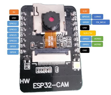
Pin assignment of the ESP32-CAM
Connection and circuit
As already mentioned, an FTDI module is required.

FTDI Modul Since we want to operate the ESP32-CAM via 5V, we have to set the jumper on the FTDI module to 5V additionally.
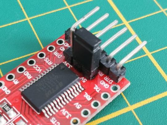
FTDI module - jumper for voltage selection So for the setup we need besides the FTDI module & the ESP32-CAM module 4 breadboard cables (20 cm, female - male) and 1 breadboard cable (10 cm, male - male), and a breadboard with min. 400 pins. FTDI ModulESP32-CAMRXUOTTXUORGNDGNDVCC5V

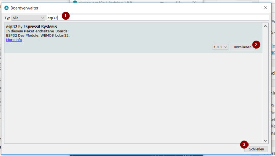
Structure of the circuit ESP32 - CAM with FTDI module However, this bridge is only needed for uploading the sketch, for operation it must be removed again. "Board: xyz" > "Board manager…". In the window of the board manager is now searched for the term "esp32" (1), there should be exactly one hit, which we install with the button "Install" (2). After the driver has been installed (this can take some time depending on the internet & computer speed of the computer) we can close this window with the button "Close" (3).
Arduino IDE - board manager, install ESP32 Although I have a 50Mbit line, the download of the approx. 32 MB package took an unusually long time, so please allow a little more time for this process. Setting up the board in the Arduino IDE If you have installed the board driver now, you have to select it and change some default values.

Configuration of the microcontroller ESP32-CAM in the Arduino IDE Upload the example from the ESP32 package The ESP32 package comes with an example for the ESP32 - CAM, if you don't have it you can download it for free from the GitHub repository espressif/arduino-esp32. Alternatively I offer you a ready configured sketch at the end of this post. Once you have uploaded this example, you will need to restart it once. This restart can be done either by using the reset button or by removing the power supply and plugging it in again. In the serial monitor of the Arduino IDE you can see the following output.

Output on the serial monitor of the Arduino IDE (after uploading the sample code) This issue stops a bit longer, which means you have to wait a bit until it continues. When the process is complete, then the connection to the Wi-Fi network is established and the IP address of the ESP32-CAM module is displayed.
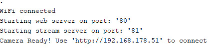
Establishing a WiFi connection Web page in browser When the WiFi connection is established, you can use the displayed IP address in the browser to display a page where you can start a stream, for example.
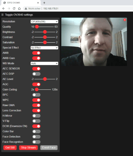
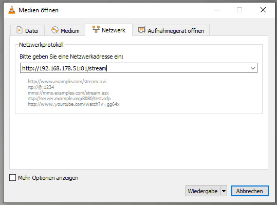
Web page in the browser of the ESP32-CAM Streaming with VLC player The free VLC player is a true all-rounder when it comes to playing multimedia files. It can also open and play network streams. I have already presented this for the Raspberry PI Camera B01 and now I would like to show it for this ESP32-CAM. The address for the stream is http://:81/stream, you can either read the IP address from your router or from the serial monitor of the Arduino IDE. In the VLC Player navigate to the main menu "Media" > "Open Network Stream…" to start the dialog "Open Media". In this dialog you have to enter the address shown above (of course with your IP address), in my case it is "http://192.168.178.51:81/stream".
start network stream in VLC player But the network stream in the VLC player can only be started if no other is started (ebsp. via the web page in the browser). Taking a picture You can also get a single picture from the active ESP32-CAM, just end the address with "/capture" instead of "/stream". A photo is now taken and displayed for 10 seconds.
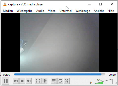
VLC Player, ESP32-CAM capture Image
Downloads
Read the full article
0 notes
Text
The Skull of the Terminator, Raspberry Pi style
The Skull of the Terminator, Raspberry Pi style
It has a Raspberry Pi 4 Model B brain and a Raspberry Pi camera in one of its eye sockets (a Pimoroni Camera Module for Raspberry Pi Zero, to be precise). Nice. There’s also an Adafruit Braincraft HAT, for machine learning-powered banter, and a Seeed Studio Grove speaker, for optimum vocalisations. Oh, and a red LED for artistic effect, in the eye socket. Because this isn’t just an objet d’art.…

View On WordPress
0 notes
Text
Top 10 Best os for pi zero w [2022]
Top 10 Best os for pi zero w [2022]
1. Aokin for Raspberry Pi Camera Module, 5MP 1080p with OV5647 Sensor Video Camera Module for Raspberry Pi Model A/B/B+, Pi 2, Raspberry Pi 3 3B+, Pi 4 and Pi Zero/Zero W with Flex Cable Buy On Amazon Compatible: camera module fit for Raspberry Pi Model A/B/B+, Pi 2B and Raspberry Pi 3B 3B+, Pi 4B, Pi Zero, Pi Zero W. Ribbon flex cable: 11.81in/30cm golden camera cable specially designed for…

View On WordPress
0 notes
Link
Feature:1. Use for Raspberry Pi 3 Model B+/ 3 / 2 / B+2. 5MP high pixels3. Support 1080P4. Mini size, easy to place and use Specification:Shot : 1/4 5M Aperture : 2.9 Focal length : ...
0 notes
Photo

Hook your raspberry pi 4 with up to 4 cameras!
Read the blog here:
http://bit.ly/2JNJZvl
Check out the product here:
http://bit.ly/2JNJZvl
Or buy it here:
https://amzn.to/2Yk4Z53
Features:
Accommodate 4 Raspberry Pi cameras on an multi camera adapter board
Take still photos in sequence (not at the same time)
Display real time video in lower frame rate
3 GPIOs required for multiplexing on the adapter board
All camera ports are FFC (flexible flat cable) connectors
Support 5MP OV5647 and 8MP IMX219 pi cameras
Support Raspberry Pi A/B/B+ and Pi 2, Pi3 B, Pi3B+
#raspberrypi#raspberry pi 4 model b#raspberry pi 4 cameras#pi camera modules#dual camera raspi#four cameras raspberry pi#Raspbrrry Pi 4
0 notes
Photo

Care – Max for Drowsiness Detection and Notification
by R N Susheel | B M Mathumitha | Mr. C Raju ""Care – Max for Drowsiness Detection and Notification""
Published in International Journal of Trend in Scientific Research and Development (ijtsrd), ISSN: 2456-6470, Volume-4 | Issue-3 , April 2020,
URL: https://www.ijtsrd.com/papers/ijtsrd30303.pdf
Paper Url :https://www.ijtsrd.com/engineering/computer-engineering/30303/care-%E2%80%93-max-for-drowsiness-detection-and-notification/r-n-susheel
ugcjournallist, listofugcapprovedjournals, researchpublication
This project proposes drowsiness detection and notification system for vehicles and a mobile application for car maintenance. The major objective of the system is to prevent the road accidents caused by driver falling asleep during the travel. The system for drowsiness detection has a camera that monitors the driver’s eye continuously. It calculates the eye aspect ratio to detect if the driver is drowsy. If found drowsy, alarm rings. In this project, a Raspberry Pi board is used for drowsiness detection and alerting the driver. The IoT based mobile application built using android studio proposed here has certain settings like next service date, interval for wheel air checking, interval for wheel alignment. The app is connected to the system using IoT. The information is sent to the system. These settings are notified to the driver through a voice module.
0 notes
Text

ORWIND PI 3 Model A+512 RAM 64QUAD 1.4GHZ
Orwind RGLS-X001 Pi 3 Model A+ is a 1.4GHz 64-bit quad-core processor, dual-band wireless LAN, Bluetooth 4.2/BLE in the same mechanical format as the Orwind RGLS-X001 Pi 1 Model A+
Broadcom BCM2837B0, Cortex-A53 (ARMv8) 64-bit SoC @ 1.4GHz | 512MB LPDDR2 SDRAM
2.4GHz and 5GHz IEEE 802.11.b/g/n/ac wireless LAN, Bluetooth 4.2/BLE | Extended 40-pin GPIO header | Full-size HDMI | Single USB 2.0 ports | CSI camera port for connecting a Orwind RGLS- X001 Pi Camera Module | DSI display port for connecting a Orwind RGLS-X001 Pi Touch Display | 4-pole stereo output and composite video port || Micro SD port for loading your operating system and storing data
5V/2.5A DC power input
.
.
.
.
.
.
.
.
.
#orwind #orwindglobal #orwindindia #orwindclub #orwindgroup #igdaily #instagood #goals #blogger #innovation #technology #onlineshopping #classic #innovative #inventions #inspiration #stayhome #staysafe #dreambig #techno #india #asia #daily #post #high #instadaily
0 notes
Link
5000円台で購入できる市販レンズを着脱可能なRaspberry Piの高品質カメラモジュール「High Quality Camera」が登場 ARMプロセッサを搭載したシングルボードコンピューターの「Raspberry Pi」から、わずか50ドル(約5400円)で購入できる高品質カメラモジュールの「High Quality Camera」が発表されました。このカメラモジュールにはソニー製の12.3メガピクセルセンサーであるIMX477が採用されており、CマウントおよびCSマウントのカメラレンズを装着することが可能です。 New product: Raspberry Pi High Quality Camera on sale now at $50 - Raspberry Pi https://www.raspberrypi.org/blog/new-product-raspberry-pi-high-quality-camera-on-sale-now-at-50/ Raspberry Piブランドから高品質カメラモジュールの「High Quality Camera」が発表されました。モジュールの詳細は以下のムービーを見ればわかります。 NEW Raspberry Pi High Quality Camera - YouTube High Quality Camera High Quality CameraはソニーのIMX477センサーを採用しており、イメージサイズは対角7.9mm。なお、正確にはIMX477のイメージサイズは対角7.857mm(1/2.3インチ)で、12.3メガピクセルのCMOSイメージセンサーを採用しています�� バックフォーカスの調整が可能な交換レンズを使用することができます。 レンズマウントはCマウントおよびCSマウントに対応。 当然ですが、Raspberry Pi向けのカメラモジュールです。 CマウントおよびCSマウントレンズを装着する場合は、レンズ用アダプターを使用する必要アリ。レンズ用アダプターには焦点を合わせるためのリングと三脚用の穴もあります。 なお、CマウントとCSマウントのレンズを装着する詳細な方法がそれぞれの���イドラインに記されています。 HQ Cam Lens Diagrams - 16 mm C-mount lens (PDF)https://static.raspberrypi.org/files/product-guides/Typical_C-Mount_Lens_Guide.pdf HQ Cam Lens Diagrams - 6 mm CS-mount lens (PDF)https://static.raspberrypi.org/files/product-guides/Typical_CS-Mount_Lens_Guide.pdf Raspberry Piの公式ブログ上には実際にHigh Quality Cameraを使用して撮影した写真が掲載されています。 Raspberry Pi財団で上級主席エンジニアとして働くサイモン・マーティン氏はブログの中で、「Raspberry Piではこれまでハッカーとカメラの間に大きなつながりが存在しました。2012年にはRaspberry Piのシングルボードコンピューターを使用して、デジタル一眼レフカメラからより多くの機能を引き出す興味深い方法が提案されました。そして2013年にはRaspberry Piと直結できるカメラモジュールのOV5647が登場。その後、赤外線感度センサーを備えたNoIR Cameraが登場し、望遠鏡に取り付けたりドローンに取り付けて植物の成長を観察したりするのに使用されました」と語り、カメラとRaspberry Piのつながりについて語っています。 しかし、OV5647は2015年に販売が終了となりました。その代替品として2016年4月に登場したのがCamera Module V2で、これはソニーの8メガピクセルイメージセンサーであるIMX219を採用したカメラモジュールです。マーティン氏がCamera Module V2の売上を調査したところ、記事作成時点までの累計販売数は170万個以上であることが明らかになったとのこと。 大ヒットとなったCamera Module V2ですが、センサーサイズが小さいため微光性能が低くなる傾向にあります。また、高価なカメラレンズを資産に持つユーザーが一眼レフカメラのように撮影時に使用するレンズを変えながら被写体を撮影することはできません。そのため、High Quality CameraではCamera Module V2の弱点を補う形でセンサーサイズを大きくし、CマウントおよびCSマウントに対応したとのこと。 以下の写真はCamera Module V2でRaspberry Pi 4を撮影したもの。問題なく撮影できていますが全体的に薄暗く、マイコンボード上の細かな文字を拡大するとぼやけてしまっているのがわかります。 同じRaspberry Pi 4をHigh Quality Cameraで撮影すると、全体がかなり明るくなり、ボード上の数字や「Raspberry Pi 4」の文字もハッキリ識別可能です。 Camera Module V2はレンズが一体となったカメラモジュールでしたが、High Quality Cameraはレンズが付属しておらず、CマウントおよびCSマウントの市販のカメラレンズを装着可能です。また、専用カメラレンズとして6mmの広角CSマウントレンズが25ドル(約2700円)、16mmの望遠Cマウントレンズが50ドル(約5400円)で販売されています。なお、High Quality Cameraに対応しているのは2012年2月15日に発売されたRaspberry Pi Model B以降のモデルほぼすべてだそうです。 テクノロジーレビューサイトのTom's HardwareはHigh Quality Cameraを「優れた柔軟��と解像度によりHigh Quality Cameraは勝者となった」と評しています。 Raspberry Pi High Quality Camera Review: Interchangeable Lenses, Powerful Sensor | Tom's Hardware https://www.tomshardware.com/reviews/raspberry-pi-high-quality-camera Tom's HardwareはHigh Quality Cameraの優れた点として、「交換式レンズに対応することで優れた柔軟性を提供している点」「三脚穴によりもたらされる優れた安定性」「Raspberry Piのモデルに関係なく使用できる点」の3つを挙げ、マイナス点としては「ソフトウェアが開発中である点」「レンズが含まれていない点」「レンズを合わせると高価になる点」の3つを挙げています。 High Quality Cameraは以下のページから購入可能で、価格は50ドル。また、High Quality Cameraの詳細な取り扱い方法が書かれたカメラガイドがPDF形式で無料公開されています。 Buy a Raspberry Pi High Quality Camera – Raspberry Pi ・関連記事 新「Raspberry Pi 4」が4Kサポート&CPU高速化など大幅にスペックアップして登場 - GIGAZINE Raspberry Pi 4の「特定の解像度でWi-Fiが不安定になる」問題を実際に検証してみた - GIGAZINE Raspberry Pi公式ブログは18台のRaspberry Pi 4上で構築されている - GIGAZINE 「Raspberry Pi 4」は発熱が懸念されるも新ファームウェアで改善可能だとのレビュー結果 - GIGAZINE 発熱が気になる「Raspberry Pi 4」のケースにドリルで穴を開けてファンを取り付けてしまった猛者が現れる - GIGAZINE Tweet 2020年05月01日 15時00分00秒 in ハードウェア, 動画, Posted by logu_ii You can read the machine translated English article here.
0 notes
Text
Can Edge Analytics Become a Game Changer?

One of the major IoT trends for 2019 that are constantly mentioned in ratings and articles is edge analytics. It is considered to be the future of sensor handling and it is already, at least in some cases, preferred over usual clouds.
But what is the hype about?
First of all, let’s go deeper into the idea.
Edge analytics refers to an approach to data collection and analysis in which an automated analytical computation is performed on data at a sensor, network switch or another device instead of sending the data back to a centralized data store. What this means is that data collection, processing and analysis is performed on site at the edge of a network in real time.
What is the hook?
You might have read dozens of similar articles speculating over the necessity of any new technique, like “Does your project need Blockchain? No!” Is Edge Analytics yet another one of such gimmicky terms?
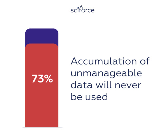
The truth is, it is really a game changer. At present, organizations operate millions of sensors as they stream endless data from manufacturing machines, pipelines and all kinds of remote devices. This results in accumulation of unmanageable data, 73% of which will never be used.
Edge analytics is believed to address these problems by running the data through an analytics algorithm as it’s created, at the edge of a corporate network. This allows organizations to set parameters on which information is worth sending to a cloud or an on-premise data store for later use — and which isn’t.
Overall, edge analytics offers the following benefits:

Edge analytics benefits
Reduced latency of data analysis: it is more efficient to analyze data on the faulty equipment and immediately shut it up instead of waiting for sending data to a central data analytics environment.
Scalability: accumulation of data increases the strain on the central data analytics resources, whereas edge analytics can scale the processing and analytics capabilities by decentralizing to the sites where the data is collected.
Increased security due to decentralization: having devices on the edge gives absolute control over the IP protecting data transmission, since it’s harder to bring down an entire network of hidden devices with a single DDoS attack, than a centralized server.
Reduced bandwidth usage: edge analytics reduces the work on backend servers and delivers analytics capabilities in remote locations switching from raw transmission to metadata.
Robust connectivity: edge analytics potentially ensures that applications are not disrupted in case of limited or intermittent network connectivity.
Reduce expenses: edge analytics minimizes bandwidth, scales operations and reduces the latency of critical decisions.
Edge architecture
The connected physical world is divided in locations — geographical units where IoT devices are deployed. In an Edge architecture, such devices can be of three types according to their role: Edge Gateways, Edge Devices, and Edge Sensors and Actuators.
Edge Devices are general-purpose devices that run full-fledged operating systems, such as Linux or Android, and are often battery-powered. They run the Edge intelligence, meaning they run computation on data they receive from sensors and send commands to actuators. They may be connected to the Cloud either directly or through the mediation of an Edge Gateway.
Edge Gateways also run full-fledged operating systems, but as a rule, they have unconstrained power supply, more CPU power, memory and storage. Therefore, they can act as intermediaries between the Cloud and Edge Devices and offer additional location management services.
Both types of devices forward selected subsets of raw or pre-processed IoT data to services running in the Cloud, including storage services, machine learning or analytics services. They receive commands from the Cloud, such as configurations, data queries, or machine learning models.
Edge Sensors and Actuators are special-purpose devices connected to Edge Devices or Gateways directly or via low-power radio technologies.

A four-level edge analytics hierarchy
Edge analytics going deep
If edge analytics is only paving its way to ruling the next-generation technology, deep learning, a branch of machine learning for learning multiple levels of representation through neural networks, has been already there for several years.
Will deep learning algorithms applied to edge analytics yield more efficient and more accurate results? In fact, an IDC report predicts that all effective IoT efforts will eventually merge streaming analytics with machine learning trained on data lakes, marts and content stores, accelerated by discrete or integrated processors by 2019. By applying deep learning to edge analytics, devices could be taught to better filter unnecessary data, saving time, money and manpower. One of the most promising domains of integrating deep learning and edge analytics is computer vision and video analytics.
The underlying idea is that edge analytics implements distributed structured video data processing, and takes each moment of recorded data from the camera and performs computations and analysis in real time. Once the smart recognition capabilities of a single camera are increased and camera clustering enables data collision and cloud computing processing, the surveillance efficiency increases drastically, at the same time reducing the manpower requirements.
Deep learning algorithms integrated into frontend cameras can extract data from human, vehicle and object targets for recognition and incident detection purposes significantly improving accuracy of video analytics. At the same time, shifting analytics processing from backend servers and moving them into the cameras themselves is able to provide end users with more relevant real-time data analysis, detecting anomaly behavior and alarm triggering during emergency incidents which does not rely on backend servers. This also means that ultra-large scale video analysis and processing can be achieved for projects such as safe cities where tens of thousands of real-time.
Experimenting with edge computers
Edge computers are not just a new trend, but they are a powerful tool for a variety of AI-related tasks. While Raspberry Pi has long been the gold standard for single-board computing, powering everything from robots to smart home devices, the latest Raspberry Pi 4 takes Pi to another level. This edge computer has a PC-comparable performance, plus the ability to output 4K video at 60 Hz or power dual monitors. Its competitor, the Intel® Movidius™ Myriad™ X VPU has a dedicated neural compute engine for hardware acceleration of deep learning inference at the edge. Google Coral adds to the competition offering a development board to quickly prototype on-device ML products with a removable system-on-module (SoM). In our experiments, we used them as a part of a larger computer vision project.
Real-time human detection
Human detection is a process similar to object detection and in the real world settings it takes raw images from (security) cameras and puts them in the camera buffer for processing in the detector&tracker. The latter detects human figures and sends the processed images to the streamer buffer. Therefore, the whole process of human detection can be divided into three threads: camera, detector&tracker and streamer.

As the detector, we used sdlite_mobilenet_v2_coco from TensorFlow Object Detection API, which is the fastest model available (1.8 sec. per image).
As the tracker, we used MedianFlow Tracker from the OpenCV library, which is also the fastest tracker (30–60 ms per image).
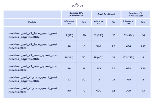
To compare how different devices work on the real-time object detection problem, we tested Coral Dev Board and Coral Accelerator for human detection from two web-cameras against Desktop CPU with Coral Accelerator and Raspberry Pi with the same Accelerator:
Coral Accelerator — Edge TPU Accelerator v.1.0, model WA1
Coral Dev Board — Edge TPU Dev Board v.1.0 model AA1
RaspberryPi — Raspberry Pi 3 Model B Rev 1.2
Desktop CPU — Intel Core i7–4790
WebCam — Logitech C170 (max width/height — 640x480, framerate — 30/1 — used these parameters)
As it turned out, the desktop CPU showed the lowest inference and the highest fps, while Raspberry Pi demonstrated the lowest performance:
Chess pieces object detection
Another experiment addressed a more general object detection task, as we used this method for model conversion for Coral Dev Board and Accelerator and one of the demo scripts for object detection. We compared the performance of the Coral Dev Board and Accelerator against the Neural Compute Stick 2. For the latter, we used the openVino native model-optimization converter and this model+script.
Our experiments proved that the Coral Dev Board showed the lowest inference, while the Intel Neural Compute Stick 2 had the inference more than four times higher:

These experiments confirm the potential of modern edge devices that show similar performance with desktop CPUs.
Challenges and Restrictions
Deep learning can boost accuracy, turning video analytics into a robust and reliable tool. Yet, its accuracy usually comes at the cost of power consumption. Power balancing is an intricate task based on improving the performance of edge devices, introducing dedicated video processing units, and keeping neural networks small.
Besides, as only a subset of data is processed and analyzed in the edge analytics approach, a share of raw data is discarded and some insights might be missed. Therefore, there is a constant tradeoff between thorough collection of data offline and prompt analysis in real time.
Therefore, edge analytics may be an exciting area of great potential, but it should not be viewed as a full replacement for central data analytics. Both can and will supplement each other in delivering data insights and add value to businesses.
0 notes
Text
A People-Following Mobile Robot Using Kinect and a Laser Scanner- Juniper Publishers

Abstract
This research proposes a people-following mobile robot system that is equipped with Kinect RGB-D camera and a laser scanner, in which the Kinect’s skeleton tracking function helps, identify people in the depth image. First, the system selects a person who raises his two hands as the target to follow. Second, the system identifies the target to follow from the person’s location and color characteristics of clothes. When an occlusion occurs, the system uses the information from the laser scanner to guide the motion of the mobile robot and tries to re-recognize the target to follow at the same time. The people-following mobile robot accomplishes a human detection and follows only the target even if more than two people are located around the target person. The research conducts several experiments and shows the effectiveness of the proposed system to identify and follow a human in an indoor environment.
Keywords: Mobile robot; People-following; Kinect camera; Laser scanner; Human skeleton detection; Gesture recognition
Introduction
The ability to detect human motion, gestures, and behavior is an important task for service robots [1]. A robot that can carry luggage and follow a customer can be very helpful in many situations. Such a service robot should be able to interact with people and co-exist with people in a crowded environment designed basically for humans. Equipped with cameras, a robot can obtain images of the environment where it is situated through visual sensors and with the ability of visual perception can recognize objects and determine their locations. However, using only a 2D image is very difficult to identify or track the target in a 3D world. Kinect is a RGB-D camera combining a RGB image and a 3D depth image that can recognize the movement of a human. Kinect can extract the 3D positions of a human body’s joints, which can then be further processed to recognize human gestures. Kinect has been applied in various application fields such as health care, sport training, gaming, security, 3D construction, human motion recognition and many others. For instance, Kinect technology has been found to be very useful in various healthcare related services, such as physical therapy exercises, sport rehabilitation games, motor skill training, monitoring patient activities, medical operation room assistance, and other clinical areas [2].
Kinect (Kinect for Windows SDK V2.0) is able to track the skeletons of multiple persons by using only their depth image, and so it can be very easy to create gesture-driven applications [3]. Kinect can track at most 25 joint points of a human body skeleton and up to 6 persons at the same time. With the availability of tracking a human body’s skeleton joints positions and orientations for each user, the task of feature extract becomes much easier. One only needs to determine which joints are the most important for each activity.
Gesture recognition can be broadly categorized into gesture detection, pose estimation and gesture classification. Hand gesture detection is even a critical factor in sign language understanding. Because a hand is a smaller part in the human body, so detection and classification of hand gestures may be even more complex. In general, to develop a useful Kinect application involving human motion recognition, the following steps are typically required:
o Real-time human skeleton tracking;
o Recognition of the semantics of the activity or gesture formed by the motion; and
o Actions triggered by the detection of the particular motion.
There are many more reports of useful applications of Kinect in mobile robot systems. A Kinect based people- following mobile robot system was designed with its mission to keep the person in the centre of depth images and in at a fixed distance away from the mobile robot [4]. An autonomous robot equipped with 3 Kinects was built to follow and track a person [5]. The system selected a person who raised a hand as the target to follow at the beginning. The system could then identify a person from the person's location and characteristics of clothes and re-recognize the target to follow when an occlusion occurred. A Kinect was installed in a mobile frame at a height of around 120cm [6]. The system utilized color, depth, and skeleton frames from Kinect to find and track people for basic robotic movements like wander around and follow- me. Kinect was found useful in building an indoor map. For instances, Kinect and a laser range finder were used together to acquire environmental 2D map information [7]. In addition, 3D point cloud data from Kinect were transformed into an enhanced 2.5D and then down to a 2D grid map [8].
For the first step toward an autonomous service robot, we study a people-following mobile robot system, which is equipped with Kinect RGB-D camera and a laser scanner. Kinect is used to track human skeletons and to identify people from the depth image. The system selects a person who raises his two hands as the target to follow at the beginning. The system then identifies the target to follow from the person's location and RGB color characteristics of clothes. In the case of target occlusion, the system switches over to use the information from a laser scanner to plan the robot motion [9]. The robot is a two-wheel differential driven mobile robot controlled by a FPGA controller operating in a closed-loop speed PI control with a built-in encoder odometer to record its pose (position and orientation).
System Overview
The experimental people-following mobile robot system as shown in Figure 1 includes mainly a differential-drive mobile robot platform, a Kinect camera V2, a laser scanner SICK 200, a notebook computer, and a 24V lithium polymer battery. The mobile robot platform consists of two independent driving wheels and two free wheels. The actuator of the driving wheel is the dc motor with gear and encoder, which is in velocity PI control. The radius of driving wheel is r=75mm, and the distance of two driving wheels is 2L, where L=20mm. The wheel is actuated by a dc motor (motor maximum no-load speed 3000rpm) with a 17:1 gear reducer, and the motor encoder has a resolution of 68,650ppc. The motor speed control system is built on an Altera DE0-nano FPGA development board running at a system clock rate of 50Mhz. Motor speed PI control and series communication modules are implemented using Verilog HDL and synthesized by an Altera Quartus II EDA tool. The Kinect camera processing and connected curve generation programs are programmed in Visual C++ for PC.
Define to be the position of the middle of the two wheels in the world frame {W}. The origin of the robot base frame {B} is assigned to the middle of the two driving wheels, and is the yaw angle of the x-axis of the robot frame with respect to the x-axis of the world reference frame, as shown in Figure 2. Thus, is the pose (position and orientation) of the mobile robot in the world coordinate frame Figure 2. Coordinate frames of the mobile robot system: the world frame {W}, the robot base frame {B} with origin at the middle of the two driving wheels, and the Kinect coordinate frame {K}.
A Kinect V2 camera is installed at the upper middle of the free wheels of the mobile robot. The Kinect has two cameras, the left one is the RGB camera to obtain color images, and the middle one is the IR depth camera. The RGB color image has a resolution of 1920x1080 at 30 frames per second. The IR depth (D) image is 16-bit (in mm) at a resolution of 512x424, and the sensor range is between 0.5m and 8.0m at 30 frames per second. The depth of each pixels is computed based on the phase shift of the emitted modulated light and corresponding reflected light. The Kinect coordinate system {K} is centered on the Kinect's IR sensor as shown in Figure 2, in which the Y-axis points upward, the Z-axis points where the Kinect is pointing, and the X-axis is to the left (or cross-product of Y-axis and Z-axis). In this work, the Kinect is used mainly for human motion tracking and recognition as well as target person detection.
A laser scanner, SICK S200, is installed at the front end of the robot platform. Its main function here is to avoid obstacles such as doors, walls, and people. The principle of a laser scanner is based on time- of-flight. It can scan a range of 270 degrees in a resolution of 0.5 degrees and returns 16-bit distance values between 1.0cm and 800cm. For practical reasons, only 120 degrees of a scanned range are used here as shown in Figure 2. The laser range data’s updating time is 0.5 seconds.
Figure 3 shows the overall system block diagram of the people-following mobile robot control system. The system's operation is according to two external sensors (Kinect & laser scanner) and internal sensors (motor encoders). When the Kinect system is successful at detecting and tracking the target person, the mobile robot follows his steps; otherwise, the mobile robot is guided by the laser scanner to avoid local obstacles and tries to return to the state of tracking the target person. The mobile robot's pose trajectory history is recorded from motor encoder odometry.
Target person recognition and detection
Human motion tracking and recognition
One of the most important Kinect features is body tracking, as the Kinect can track a total of 25 skeletal joints per person. With Kinect for Windows SDK V2.0 one can extract the 3D positions of a human body's joints, which can then be further processed to recognize human gestures. In this work, we used the data of a body skeleton: joint rotations, positions and angles between joints for tracking and recognition of the target person to follow. The system only selects the person who raises his two hands as the target to follow. Here, we build a Kinect application system using only a single depth image to supports the following human motion tracking and recognition tasks:
Step 1: Record the sequence of hand-raising gestures (Figure 4) by using Kinect Visual Gesture Builder in Kinect Studio, which is used to identify the target to follow.
Step 2: Track human body skeletons up to 6 persons (called body frames) at the same time.
Step 3: Compare body gestures with the recorded target sequence and return a confidence value between 0 and 1. A confidence value of 0.95 indicates that a target person is successfully identified. A RGB model image is saved for target person detection later.
Target person detection
Target person detection is based on a comparison of color characteristics of his clothes in a body ROI (Region-of-interest) as shown in Figure 5. The body ROI of size 250x250 is formed from 4 human body joints in a detected human skeleton: spine base, shoulder right, shoulder left and spine shoulder. First, the RGB image, 0 ≤ R,G,B ≤ 255 , is transformed to the HSV image, 0 ≤ H ≤ 180 , 0 ≤ S ≤ 255 , and 0 ≤ V ≤ 255 . To compare two histograms, the histogram I from the input image and the histogram M of the model image, a metric of intersection d (I, M) is used to express how well both histogram match, whereby
When, d(I,M) ≥ 0.25 , it indicates that the target person is detected successfully. In summary, the program flowchart of human motion detection and target person detection is shown in Figure 6.
People Following Motion Planning
Mobile robot motion planning by tracking target person
Let v and ω be the instantaneous linear velocity command of the origin and angular velocity command of the robot base frame, respectively. Let (xc, xc, zc) be the detected neck joint point of the target person in the Kinect coordinate frame {K}. Define to be the angle of the target person with respect to the robot base frame. The mobile robot motion command ( v and ω ) is planned according to target tracking position (xc,xc,zc) . The linear velocity command v is a nonlinear function consisting of linear segments, dead-zones and saturations as below,
Where, parameters zmax = 300 cm, zmln = 150 cm, z1 = 30 cm, z0 = 45 cm, vmax = 27.5 cm/sec, and vmln = 20.6 cm/sec. Similarly, the angular velocity command ω is planned as below,
Mobile robot motion planning by laser scanner
The above target tracking planning strategy will fail whenever the vision system fails to update the new location of the target person. In such a case, the laser scanner is used to resolve the difficult situation. The range data s (in cm) of the laser range scanner in a range of 120 degrees as shown in Figure 2 are rewritten as
Where, α = 0.5 (j — 271) degrees, 151 ≤ j ≤ 391 and safety threshold smln = 70 cm. The value of n(α) = 1 denotes that the line of sight at an angle of α relative to the x-axis of the robot's base frame is free of any obstacle; otherwise, n(α) = 0 denotes that there is an obstacle in this direction angle. Let θ* be the previous target tracking angle (relative to the x-axis of the world frame) just before a failed detection of a new target object occurs, and θ is the current mobile robot's orientation angle.
The mobile robot now plans to move forward, if n(α) = 1 , for -45° <α< 45° , and cos(θ-θ')> 0 ; otherwise, the robot rotates in place counter clockwise (or clockwise) if there is more free range in the left-side than the right-side (or the right- side than the left side). The above procedure is repeated until the target object is verified and detected again. Figure 7 shows the program flowchart of guidance by a laser scanner. Because the robot always maintains a minimum safety distance of 70 cm in its front end and its only mission is to follow the target person, it therefore seldom needs to consider the problem of obstacle avoidance when the target object is in front of it.
Experimental Results
During the experiments, the maximum robot's speed is set to 25.5cm/sec and the target's proximity distance to 30 cm for the safety reason. In the first people-following experiment, there are two persons around the target person. First, a person raises his two hands to be assigned as the target to follow. The mobile robot then identifies and tracks the target to follow from the target person's location and color characteristics of his clothes. The people-following mobile robot accomplishes a human detection and follows only the target of following even if more than two people are located around the target person. Figure 8 shows multi-shots of the first people-following mobile robot experiment. Multi-shots of the first people-following mobile robot experiment; the target person identification is performed right before t = 0 sec.; and tracking the target person starts right after.
In the second people-following mobile robot experiment, there is one person walking through the space between the mobile robot and the target person during the experiment. The mobile robot accomplishes the target person identification and detection and successfully follows only the target person even if a person is walking across between the mobile robot and the target person. Figure 9 shows multi-shots of the second mobile robot experiment. At time t = 21sec. a person appears in the front of the robot and an occlusion occurs, the system re-recognizes the target person after the breaking person who appeared walks away from the robot.
In the third example, the mobile robot accomplishes the task of following the target person to walk through a hallway and through doors inside an office building. Figure 10,11 show multi-shots and the mobile robot trajectory of the third people-following experiment, respectively. Whenever the target person walks inside a door, an occlusion easily occurs. The system always re-recognizes the target person after the robot passes through the door by using the information from the laser scanner. In summary, the experimental robot system recognizes the target to follow successfully on more than 95% of the trials and the target person recognition time is less than 0.1 seconds.
Conclusion
This paper has proposed a people-following mobile robot system based on a Kinect sensor and a laser scanner. The robot is able to follow a target person if that person is identified through Kinect. When the target person disappears, the robot uses the range information obtained from a laser scanner to plan its motion and to re-recognizes the target person at the same time. The experimental results show that the people-following mobile robot accomplishes the task of tracking only the target person to follow even if more than two people are located around the target person or the mobile robot. Furthermore, the mobile robot also accomplishes the task of following the target person to walk through a hallway and through doors inside an office building. In our experiments, the experimental robot system recognizes the target to follow successfully on more than 95% of the trials and the target person recognition time is less than 0.1 seconds. The main advantage of the proposed approach is that the system combines a Kinect camera and a laser scanner so that the system can look around the space and re-cognize the target when a target person is out of the sensing region of Kinect.
Acknowledgement
This work is supported by a grant from Taiwan's Ministry of Science and Technology, MOST 106-2221-E-011-151.
For more open access journals please visit: Juniper publishers For more articles please click on: Robotics & Automation Engineering Journal
0 notes
Link
Description: This camera is compatible with any version of Raspberry Pi. You can adjust it based on the distance. Features: 5 million pixels OV5647 sensor chip Camera parameters: CCD ...
0 notes
Text
Raspberry Pi 3 Model A+(Plus) 3A+ Mainboard With 2.4G & 5G WiFi 4.2 Bluetooth Quad-core 1.4GHz Broadcom processor

https://sensoq.com/product/raspberry-pi-3-model-aplus-3a-mainboard-with-2-4g-5g-wifi-4-2-bluetooth-quad-core-1-4ghz-broadcom-processor/ Overview: The Raspberry Pi 3 Model A+ is the latest product in the Raspberry Pi 3 family range, weighing in at just about 29g. Like the Raspberry Pi 3 Model B+ , it boasts a 64-bit quad core processor running at 1.4?GHz, dual-band 2.4?GHz and 5?GHz wireless LAN, and Bluetooth 4.2/BLE. The dual-band wireless LAN comes with modular compliance certification, allowing the board to be designed into end products with significantly reduced wireless LAN compliance testing, improving both cost and time to market. The Raspberry Pi 3 Model A+ has the same mechanical footprint as the older Raspberry Pi 1 Model A+ . Specifications: The Raspberry Pi 3 Model A+ extends the Raspberry Pi 3 range into the A+ board format. Broadcom BCM2837B0, Cortex-A53 (ARMv8) 64-bit SoC @ 1.4GHz 512MB LPDDR2 SDRAM 2.4GHz and 5GHz IEEE 802.11.b/g/n/ac wireless LAN, Bluetooth 4.2/BLE Extended 40-pin GPIO header Full-size HDMI Single USB 2.0 ports CSI camera port for connecting a Raspberry Pi Camera Module DSI display port for connecting a Raspberry Pi Touch Display 4-pole stereo output and composite video port Micro SD port for loading your operating system and storing data 5V/2.5A DC power input Here is WIKI for more info. Package Included: 1 x Raspberry Pi 3 Model A+ 1 x Multi-language user manual Sensoq.com
Read More >>>
https://sensoq.com/product/raspberry-pi-3-model-aplus-3a-mainboard-with-2-4g-5g-wifi-4-2-bluetooth-quad-core-1-4ghz-broadcom-processor/
0 notes
Text
Raspberry Pi 3 Model A+(Plus) 3A+ Mainboard With 2.4G & 5G WiFi 4.2 Bluetooth Quad-core 1.4GHz Broadcom processor
https://dkwana.com/product/raspberry-pi-3-model-aplus-3a-mainboard-with-2-4g-5g-wifi-4-2-bluetooth-quad-core-1-4ghz-broadcom-processor/ Raspberry Pi 3 Model A+(Plus) 3A+ Mainboard With 2.4G & 5G WiFi 4.2 Bluetooth Quad-core 1.4GHz Broadcom processor Overview: The Raspberry Pi 3 Model A+ is the latest product in the Raspberry Pi 3 family range, weighing in at just about 29g. Like the Raspberry Pi 3 Model B+ , it boasts a 64-bit quad core processor running at 1.4?GHz, dual-band 2.4?GHz and 5?GHz wireless LAN, and Bluetooth 4.2/BLE. The dual-band wireless LAN comes with modular compliance certification, allowing the board to be designed into end products with significantly reduced wireless LAN compliance testing, improving both cost and time to market. The Raspberry Pi 3 Model A+ has the same mechanical footprint as the older Raspberry Pi 1 Model A+ . Specifications: The Raspberry Pi 3 Model A+ extends the Raspberry Pi 3 range into the A+ board format. Broadcom BCM2837B0, Cortex-A53 (ARMv8) 64-bit SoC @ 1.4GHz 512MB LPDDR2 SDRAM 2.4GHz and 5GHz IEEE 802.11.b/g/n/ac wireless LAN, Bluetooth 4.2/BLE Extended 40-pin GPIO header Full-size HDMI Single USB 2.0 ports CSI camera port for connecting a Raspberry Pi Camera Module DSI display port for connecting a Raspberry Pi Touch Display 4-pole stereo output and composite video port Micro SD port for loading your operating system and storing data 5V/2.5A DC power input Here is WIKI for more info. Package Included: 1 x Raspberry Pi 3 Model A+ 1 x Multi-language user manual
Read More
https://dkwana.com/product/raspberry-pi-3-model-aplus-3a-mainboard-with-2-4g-5g-wifi-4-2-bluetooth-quad-core-1-4ghz-broadcom-processor/
0 notes