#raspberrypi zero
Explore tagged Tumblr posts
Visit Tumblr Blog
Explore Tumblr blogs with no restrictions, modern design and the best experience.
Last Seen Tumblr Blogs


Fun Fact
Celebrities use Tumblr as well.
Text

The Flipper Zero is a pocket-sized multi-tool for hardware and software hackers, security researchers, and enthusiasts interested in RFID, NFC, Bluetooth, and IR wireless protocols. It's making headlines as the Canadian government considers its legality due to concerns about car theft, but this device cannot unlock or steal cars. Developers have recently introduced a $49 Video Game Module that turns the Flipper Zero into a mini-game console, expanding its capabilities. The Video Game Module boosts the Raspberry Pi RP2040 microcontroller to 133 Hz, enhancing its capability for video output. Without the Video Game Module, Flipper Zero users are typically restricted to the 1.4 inch, 128 x 64 pixel monochrome display for gaming. Adding the module provides an HDMI port for external display, supporting resolutions up to 640 x 480 pixels at 60 Hz. Interactivity is facilitated through Flipper Zero’s D-Pad and buttons, while the module also offers motion controls via a 6-axis gyroscope and accelerometer and USB-C port for external controller connection. Additionally, the USB-C port on the Flipper Zero can function in host or device modes, enabling potential use with other devices as a game controller or mass storage device. Flipper Zero supports various wireless connections, allowing you to utilize the Video Game Module's motion sensors as a wireless air mouse for computer interactions. Developers have created demo apps and games such as a digital oscilloscope and an Arkanoid-like game, along with an air mouse app. The Flipper Zero Game Engine is available for developers interested in creating their own games utilizing the device's hardware. More information is provided in the Flipper Zero Video Game Module announcement, which includes links to firmware and schematics for the module. Other features of the Video Game Module include 11 GPIO pins, two ground pins, and a 3.3V power pin. It can also function independently, without connecting to the Flipper Zero. Available for $49 from the Flipper Zero shop or for €49 from Lab 401.


#Computer#Smartphone#Technology#console#Flipper#flipperzero#flipperzerovideogamemodule#Game#hacker#hackertoy#Liliputing#Module#raspberrypi#rp2040#toy#turns#Video#Zeros
1 note
·
View note
Text

C:// Baby Hackers Archives: MakeUseOf.Com __
C:// Data Research: LINUX, Single-Board Computing, IoT, Cybersecurity, Home-brewing, Emulators, ETech, Nintendo DS, Cool Tech, Arduino, RaspberryPi, Beagle Bone, Moodle, SLIDE Wiki, MUVE, Virtual Learning Environments, Interactive Digital Video Games, Teaching & Learning a innovation Park, Collaborative Learning, Collaborative Software, Learning Mgmt Systems, Screen-casting, Augmented Reality, Artificial Intelligence Technology, Enterprise Resource Planning, Electronically Based Teaching Materials, the MARLOT Repository, 5 Phases in ADDIE, Sharable Interoperability Framework, Sharable Content Object Reference Model, Pedology, Immersive Interactive & Fun Learning Experiences __
C:// Download & Use: DISCORD, MINDCRAFT & ROBLOX, STAR-FALL, TeachMe App, PBS Kids Video — Research How Learning & Teaching Code & Programming Increases Cognitive Functions in Kids & Adults _
C:// Happy Reading.. Much More to Come.. Enjoy!! _
0 notes
Text
Raspberry Pi Projekt: Prozessinformationen auf OLED Display anzeigen
Wie du am Raspberry Pi ein OLED Display anschließt und programmierst, habe ich dir bereits gezeigt. Im heutigen Beitrag soll es darum gehen wie du Prozessinformationen auf dem OLED Display visualisierst. Es ist hier empfehlenswert ein großes Display zu verwenden, da die Daten, welche angezeigt werden sollen, doch recht umfangreich sind (oder man muss Abstriche bei den Daten machen). https://youtu.be/nOQnx6_ekVE Für diesen Beitrag verwende ich den Raspberry Pi Zero 2 WH, da mein eigentlich für solche Beiträge verwendete Raspberry Pi 3b+ nun in ein RetroPi verwandelt wurde. Jedoch steht der kleine Pi Zero 2 dem großen in nichts nach und kann für solche Projekte ebenso verwendet werden und du kannst dieses auch auf dein Pi nachbauen.
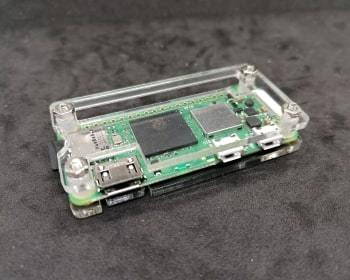
Acrylgehäuse für den Raspberry Pi Zero
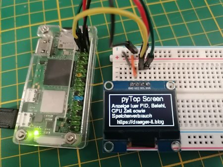
Splashscreen des Python Projektes - "pyTop Screen"
Daten aktuellen Prozessen auf dem OLED-Display Die Idee zu diesem Beitrag kommt aus einem Kommentar zu meinem YouTube-Video OLED Display am Raspberry Pi anschließen und per I2C steuern: So geht’s!. Ich bin immer froh, wenn solch Input aus meiner Community kommt und ich damit euch helfen kann und ich ebenso neuen Content generieren kann.
Benötigte Ressourcen für dieses Projekt
Wenn du dieses kleine Projekt nachbauen möchtest, dann benötigst du: - einen Raspberry Pi* inkl. Netzteil, SD-Karte etc., - ein OLED Display mit I2C Anschluss*, - ein paar Breadboardkabel*, - ein 400 Pin Breadboard* Hinweis von mir: Die mit einem Sternchen (*) markierten Links sind Affiliate-Links. Wenn du über diese Links einkaufst, erhalte ich eine kleine Provision, die dazu beiträgt, diesen Blog zu unterstützen. Der Preis für dich bleibt dabei unverändert. Vielen Dank für deine Unterstützung!
Was soll dargestellt werden?
Auf dem Display möchte ich die laufenden Prozesse darstellen, diese kann man sich recht einfach über den Befehl top anzeigen lassen. pi@raspberrypi:~ $ top top - 10:27:00 up 1:27, 1 user, load average: 0,07, 0,06, 0,09 Tasks: 194 total, 1 running, 193 sleeping, 0 stopped, 0 zombie %CPU(s): 0,5 us, 0,6 sy, 0,0 ni, 98,8 id, 0,1 wa, 0,0 hi, 0,0 si, 0,0 st MiB Spch: 426,7 total, 102,6 free, 132,7 used, 191,5 buff/cache MiB Swap: 100,0 total, 7,6 free, 92,4 used. 229,0 avail Spch PID USER PR NI VIRT RES SHR S %CPU %MEM ZEIT+ BEFEHL 17628 mysql 20 0 614080 67592 9212 S 1,3 15,5 3:49.26 mariadbd 22393 pi 20 0 11476 3204 2612 R 1,3 0,7 0:01.13 top 839 zabbix 20 0 128416 3552 2988 S 0,3 0,8 0:01.97 zabbix_server 857 zabbix 20 0 132984 2092 1808 S 0,3 0,5 0:00.36 zabbix_server 1 root 20 0 34948 5260 3568 S 0,0 1,2 0:28.14 systemd 2 root 20 0 0 0 0 S 0,0 0,0 0:00.03 kthreadd 3 root 0 -20 0 0 0 I 0,0 0,0 0:00.00 rcu_gp 4 root 0 -20 0 0 0 I 0,0 0,0 0:00.00 rcu_par_gp 5 root 0 -20 0 0 0 I 0,0 0,0 0:00.00 slub_flushwq 6 root 0 -20 0 0 0 I 0,0 0,0 0:00.00 netns 10 root 0 -20 0 0 0 I 0,0 0,0 0:00.00 mm_percpu_wq Jedoch interessieren mich hier nur die Werte, PID, %CPU, %MEM sowie der BEFEHL. Da wir diese Daten in Python weiterverarbeiten möchten, exportieren wir diese Daten mit einem Befehl in eine Semikolonseparierte CSV-Datei. (Das Komma wird in den Daten für die Gelitkommazahlen verwendet!) echo "PID;Befehl;CPU Zeit;Speicherverbrauch" > prozesse.csv && top -b -n 1 | awk 'NR > 7 { print $1 ";" $12 ";" $9 ";" $10 }' >> prozesse.csv Damit erhalten wir wie gewünscht lediglich die Daten für die Spalten PID, %CPU, %MEM, BEFEHL. PID;Befehl,CPU Zeit,Speicherverbrauch 22545;top;111;0,7 1;systemd;0,0;1,2 2;kthreadd;0,0;0,0 3;rcu_gp;0,0;0,0 4;rcu_par_gp;0,0;0,0;
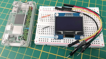
Aufbau der Schaltung - Raspberry Pi mit OLED Display
Wie bereits erwähnt baue ich die Schaltung am Raspberry Pi Zero 2 WH auf, du kannst diese aber ebenso am normalen Raspberry Pi nachbauen (solltest jedoch zusätzlich auf das ggf. geänderte Pinout achten).
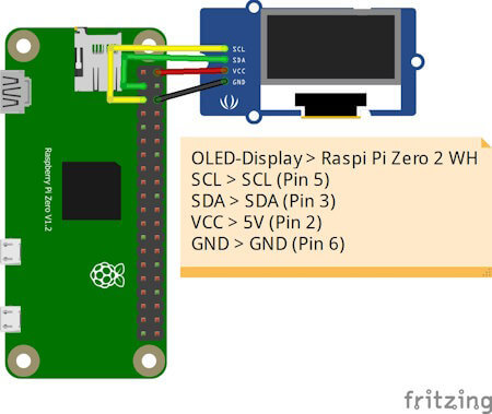
OLED-DisplayRaspberry Pi Zero 2 WHVCC5V (Pin 2)GNDGND (Pin 6)SDASDA (Pin 3)SCLSCL (Pin 5)
Python Skript im Hintergrund laufen lassen
Ich möchte das kleine Skript einmal starten und dann über die Tasten Funktionen ausführen können, während ich gleichzeitig weiterhin im geöffneten Terminalfenster arbeite. Deshalb soll das Skript im Hintergrund laufen. Es gibt hier mehrere Möglichkeiten, in diesem Beitrag möchte ich die einfachste nutzen und hänge lediglich ein & Zeichen an den Befehl und als Rückgabe erhalte ich eine PID. Mit dieser Prozess-ID kann ich dieses Skript auch jederzeit mit dem Befehl kill beenden. pi@raspberrypi:~/Python/DisplayTop $ python3 displayHello.py & 23467 pi@raspberrypi:~/Python/DisplayTop $ kill 23467 pi@raspberrypi:~/Python/DisplayTop $
Programmieren des Skriptes zum anzeigen der laufenden Prozesse
Starten wir nun und lassen die laufenden Prozesse auf dem OLED Display am Raspberry Pi anzeigen. Das Skript erstellen wir iterativ und nach jedem Schritt hast du quasi ein kleines lauffähiges Skript mit einer zusätzlichen Funktion. Schritt 1 - Willkommensnachricht anzeigen Im ersten Schritt lassen wir auf dem Display zunächst einen Text anzeigen, welcher kurz erläutert welche Daten angezeigt werden. import time from luma.core.interface.serial import i2c, spi, pcf8574 from luma.core.interface.parallel import bitbang_6800 from luma.core.render import canvas from luma.oled.device import sh1106 from PIL import ImageFont serial = i2c(port=1, address=0x3C) device = sh1106(serial) fontBig = ImageFont.truetype('FreeSans.ttf', 14) fontNormal = ImageFont.truetype('FreeSans.ttf', 10) while True: with canvas(device) as draw: draw.rectangle(device.bounding_box, outline="white", fill="black") draw.text((25, 3), "pyTop Screen", font=fontBig, fill="white") draw.text((5, 20), "Anzeige fuer PID, Befehl,", font=fontNormal, fill="white") draw.text((5, 30), "CPU Zeit sowie", font=fontNormal, fill="white") draw.text((5, 40), "Speicherverbrauch", font=fontNormal, fill="white") In meinem Fall nutze ich ein 1.3" OLED Display und musste die Schriftgröße auf 14 & 10 setzen. Hier gilt wie zuvor ein möglichst großes Display zu verwenden.
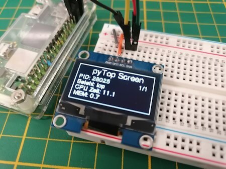
Splashscreen des Python Projektes - "pyTop Screen" Schritt 2 - exportieren der laufenden Prozesse als CSV Datei In einem Abschnitt zuvor habe ich dir gezeigt, wie der Befehl lautet, um die benötigten Daten der laufenden Prozesse in eine CSV Datei zu schreiben. Diesen wollen wir jetzt alle 2 Minuten ausführen. Damit wir eine Funktion im Hintergrund laufen lassen können, benötigen wir zusätzlich das Modul "schedule" dieses muss über den Befehl "python3 -m pip install schedule" installiert werden. pi@raspberrypi:~/Python/DisplayTop $ python3 -m pip install schedule Looking in indexes: https://pypi.org/simple, https://www.piwheels.org/simple Collecting schedule Downloading https://www.piwheels.org/simple/schedule/schedule-1.2.1-py3-none-any.whl (11 kB) Installing collected packages: schedule Successfully installed schedule-1.2.1 pi@raspberrypi:~/Python/DisplayTop $ import subprocess import schedule import time ... def loadProcessInformations(): command = 'echo "PID;Befehl;CPU Zeit;Speicherverbrauch" > prozesse.csv && top -b -n 1 | awk 'NR > 7 { print $1 ";" $12 ";" $9 ";" $10 }' >> prozesse.csv' subprocess.run(command, shell=True) loadProcessInformations() schedule.every(2).minutes.do(loadProcessInformations) ... while True: schedule.run_pending() Wenn wir das Skript ausgeführt wird, dann wird im aktuellen Verzeichnis die Datei "prozesse.csv" mit einem auszug der Daten von top angezeigt. pi@raspberrypi:~/Python/DisplayTop $ python3 pyTopScreen.py & 24037 pi@raspberrypi:~/Python/DisplayTop $ ls -ll insgesamt 12 -rw-r--r-- 1 pi pi 4987 21. Apr 11:43 prozesse.csv -rw-r--r-- 1 pi pi 1242 21. Apr 11:38 pyTopScreen.py pi@raspberrypi:~/Python/DisplayTop $ Schritt 3 - Parsen der CSV Datei in ein Dictionary Für einen einfachen Zugriff auf die exportierten Daten, parsen wir die CSV Datei in ein Dictionary. Es interessieren mich jedoch nur laufende Prozesse, diese haben eine CPU Zeit und einen Speicherverbrauch größer 0. import csv ... def loadProcessInformations(): command = 'echo "PID;Befehl;CPU Zeit;Speicherverbrauch" > prozesse.csv && top -b -n 1 | awk 'NR > 7 { print $1 ";" $12 ";" $9 ";" $10 }' >> prozesse.csv' subprocess.run(command, shell=True) prozesse_dict = {} with open('prozesse.csv', 'r') as file: csv_reader = csv.DictReader(file, delimiter=';') for row in csv_reader: pid = row cpu_zeit = float(row.replace(',', '.')) speicherverbrauch = float(row.replace(',', '.')) if cpu_zeit > 0 and speicherverbrauch > 0: befehl = row prozesse_dict = {'Befehl': befehl, 'CPU Zeit': cpu_zeit, 'Speicherverbrauch': speicherverbrauch} print(prozesse_dict) Immer wenn die neuen Daten geladen werden, werden diese zusätzlich im Terminalfenster ausgegeben. pi@raspberrypi:~/Python/DisplayTop $ python3 pyTopScreen.py { '24261': {'Befehl': 'python3', 'CPU Zeit': 100.0, 'Speicherverbrauch': 3.2}, '24530': {'Befehl': 'top', 'CPU Zeit': 5.9, 'Speicherverbrauch': 0.7} } Schritt 4 - Anzeigen der Prozessinformationen auf dem OLED Display am Raspberry Pi Kommen wir nun zum letzten Schritt und lassen die Prozessinformationen auf dem OLED Display anzeigen. Dazu müssen wir unseren bisherigen Code etwas anpassen, denn das Dictionary muss global abgelegt werden. prozesse_dict = {} def loadProcessInformations(): ... global prozesse_dict ... In der Endlosschleife in welchem der Code zum anzeigen der Daten wiederholt wird, legen wir dann eine For-Each-Schleife an welche über das Dictionary mit den Daten läuft. while True: schedule.run_pending() total = len(prozesse_dict) index = 1 for entry in prozesse_dict: showProcessEntry(entry, index, total) index += 1 time.sleep(2) Als Nächstes legen wir dann eine neue Funktion an welche einen Eintrag aus diesem Dictionary behandelt, bzw. wir übergeben lediglich die ID (die Prozess-ID / PID), zusätzlich wird noch die länge des Dictionarys sowie der aktuelle Index als Parameter übergeben (diese beiden Daten werden oben rechts im Display angezeigt). def showProcessEntry(entry, index, total): with canvas(device) as draw: draw.rectangle(device.bounding_box, outline="white", fill="black") draw.text((25, 3), "pyTop Screen", font=fontBig, fill="white") draw.text((105, 20), str(index) + "/"+ str(total), font=fontNormal, fill="white") draw.text((5, 20), "PID: "+ str(entry), font=fontNormal, fill="white") draw.text((5, 30), "Befehl: "+prozesse_dict, font=fontNormal, fill="white") draw.text((5, 40), "CPU Zeit: "+str(prozesse_dict), font=fontNormal, fill="white") draw.text((5, 50), "MEM: "+str(prozesse_dict), font=fontNormal, fill="white") Damit ist nun unser kleines Programm fertig und wir erhalten nun die Ausgabe der aktuellen Prozesse auf dem OLED-Display.
Daten aktuellen Prozessen auf dem OLED-Display Das fertige Python Skript zum anzeigen der Prozessinformationen auf einem OLED-Display Hier nun das fertige Python Skript als ZIP-Datei zum download. Programm - "pyTop-Screen" für das Anzeigen von Prozessinformationen auf einem OLED-DisplayHerunterladen import csv import subprocess import schedule import time from luma.core.interface.serial import i2c, spi, pcf8574 from luma.core.interface.parallel import bitbang_6800 from luma.core.render import canvas from luma.oled.device import sh1106 from PIL import ImageFont serial = i2c(port=1, address=0x3C) device = sh1106(serial) fontBig = ImageFont.truetype('FreeSans.ttf', 14) fontNormal = ImageFont.truetype('FreeSans.ttf', 10) fontSmall = ImageFont.truetype('FreeSans.ttf', 8) prozesse_dict = {} def loadProcessInformations(): command = 'echo "PID;Befehl;CPU Zeit;Speicherverbrauch" > prozesse.csv && top -b -n 1 | awk 'NR > 7 { print $1 ";" $12 ";" $9 ";" $10 }' >> prozesse.csv' subprocess.run(command, shell=True) global prozesse_dict prozesse_dict.clear() with open('prozesse.csv', 'r') as file: csv_reader = csv.DictReader(file, delimiter=';') for row in csv_reader: pid = row cpu_zeit = float(row.replace(',', '.')) speicherverbrauch = float(row.replace(',', '.')) if cpu_zeit > 0 and speicherverbrauch > 0: befehl = row prozesse_dict = {'Befehl': befehl, 'CPU Zeit': cpu_zeit, 'Speicherverbrauch': speicherverbrauch} print(prozesse_dict) def showProcessEntry(entry, index, total): with canvas(device) as draw: draw.rectangle(device.bounding_box, outline="white", fill="black") draw.text((25, 3), "pyTop Screen", font=fontBig, fill="white") draw.text((105, 20), str(index) + "/"+ str(total), font=fontNormal, fill="white") draw.text((5, 20), "PID: "+ str(entry), font=fontNormal, fill="white") draw.text((5, 30), "Befehl: "+prozesse_dict, font=fontNormal, fill="white") draw.text((5, 40), "CPU Zeit: "+str(prozesse_dict), font=fontNormal, fill="white") draw.text((5, 50), "MEM: "+str(prozesse_dict), font=fontNormal, fill="white") loadProcessInformations() schedule.every(15).seconds.do(loadProcessInformations) with canvas(device) as draw: draw.rectangle(device.bounding_box, outline="white", fill="black") draw.text((25, 3), "pyTop Screen", font=fontBig, fill="white") draw.text((5, 20), "Anzeige fuer PID, Befehl,", font=fontNormal, fill="white") draw.text((5, 30), "CPU Zeit sowie", font=fontNormal, fill="white") draw.text((5, 40), "Speicherverbrauch", font=fontNormal, fill="white") draw.text((15, 52), "https://draeger-it.blog", font=fontNormal, fill="white") time.sleep(3) while True: schedule.run_pending() total = len(prozesse_dict) index = 1 for entry in prozesse_dict: showProcessEntry(entry, index, total) index += 1 time.sleep(2)
Fazit & Ausblick zu Raspberry Pi Prozessinformationen am OLED Display anzeigen
Als Fazit ziehe ich ich jedoch das, dass kleine 1,3" OLED Display zu klein ist für die Informationen hier muss ich mal schauen ob es deutlich größere gibt um dieses kleine Projekt deutlich aufzuwerten. Die Nächste Ausbaustufe zu diesem Projekt könnte nun sein, drei Taster anzuschließen mit welchen man durch die aktiven Prozesse blättern kann. Zusätzlich mit einem roten Taster könnte man den Befehl kill auf einen Prozess anstoßen um den angezeigten Prozess hart zu beenden. Read the full article
0 notes
Photo


Another weekend has passed and I decided to get rid or the ugly cables connecting the raspberry pi zero to the 3d printer. For this to go well (in one end because the tri-gorilla doesn't output power in the usb-B port and in the other because the raspberry had the connections on the opposite side that I wanted) I decided to solder the 4 wires directly to the raspberry pi zero (2nd pic) and in the other end I used a female usb-b (so that I can still disconnect the whole thing easily when needed),solder the data- and data+ to the tri-gorilla and the power I connected to the aux 5v & gnd pins.
I would say the end result got pretty neat and now I'm not afraid anymore to tune the camera direction when printing since it's not so easy to disconnect the cables anymore :P
#2017#3d printer#raspberrypi zero#raspi zero#improvements#3dprinter#Anycubic#anycubicdeltaplus#raspberrypizerow
5 notes
·
View notes
Photo
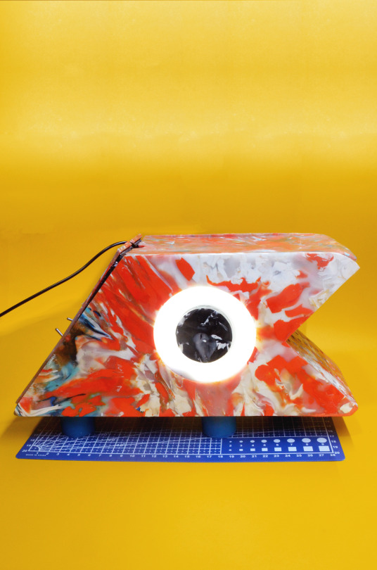
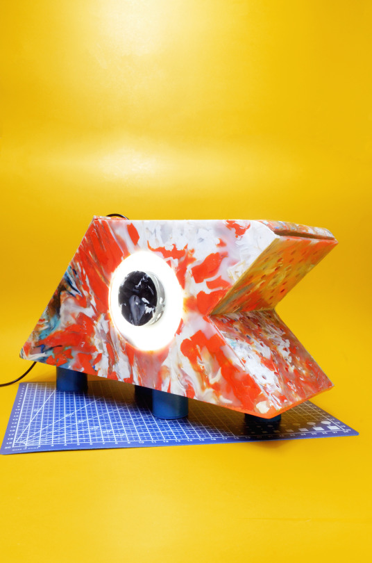
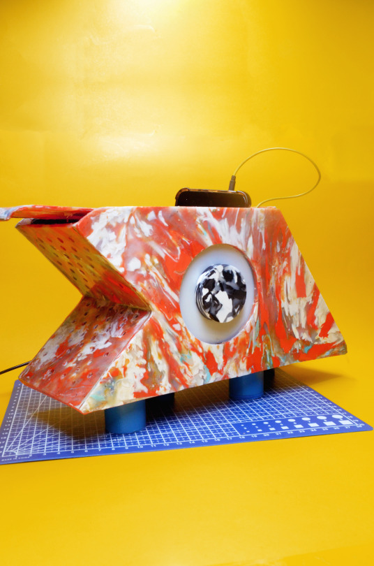

An Attempt Has Been Made | 01: OK Tuko/OK Gecko Raspberry Pi Assistant
Materials: upcycled plastics, acrylic, aluminum tubing, Sinatra board and loose electronics
The OK Tuko was made by hand during the lengthy lockdown of 2020. The Raspberry Pi (Zero W) powered Tuko, when illuminated, runs Google Assistant and Raspotify. With its insufficient battery supply, it operates whenever it feels like it. Thus making it a glorified auxiliary speaker and Pi computer - which is perfect for Retropie gaming! If I can figure out how to power it properly (coding it to turn on the Google Assistant upon booting and get the mic and speakers can work simultaneously), the Tuko can truly be my OK-faced, everyday assistant
Post project notes: If this can be re-house inside an Amazon Echo, this would be called the Echo Gecko
75 notes
·
View notes
Text
Ein Paket voll Freude
Gestern ist mein Paket, welches unter anderem den Raspberry Pi Zero W sowie das offizielle Raspberry-Kameramodul enthielt, angekommen. Ich weiß ja nicht wie es dir geht aber wenn ich ein Paket bekomme, ist das, natürlich je nach Paket, immer ein bisschen wie Weihnachten. So ähnlich war das gestern eben auch, nur dass halt nicht Weihnachten war sondern einfach ein belangloser Montag. Auf jeden Fall war ich ziemlich entzückt von dem kleinen Ding.
Für alle, die nicht wissen, was ein Raspberry Pi Zero, geschweige denn ein Raspberry Pi überhaupt ist, hier ein Link zum Wikipedia-Artikel: https://de.wikipedia.org/wiki/Raspberry_Pi Das Ganze ist eine sogenannte SoC- also eine System-on-a-Chip-Lösung. Hä, was soll das sein? Das heißt quasi dass alle oder fast alle zum Betrieb des Systems notwendigen Dinge in einem Chip vereint sind. (Schlag mich tot, wenn das genau so nicht stimmt.)
Ich besitze bereits einen "normalen" Raspberry Pi, genauer gesagt den Raspberry Pi 4. Den Raspberry Pi Zero kenne ich eigentlich schon länger, hat mich aber bis vor kurzem nicht wirklich interessiert. Allerdings sticht er vor allem wegen seiner echt kleinen Größe ins Auge.
Vielleicht kennst du den Begriff "Kleinod". Bedeutet so viel wie "Schmuckstück". Für mich ist der Raspi natürlich nicht nur ein Schmuckstück, er hat ja viele Funktionen, weit mehr als ein "herkömmliches" Schmuckstück, sei es jetzt ein Ring oder ein Armband oder dergleichen. Aber mich begeistern eben nicht nur die Funktionen und die Technik des Raspis, sondern eben auch der optische Aspekt von dem Ding, dieses Gefühl wenn man ihn ansieht bzw. in der Hand hält. Diese Begeisterung, dass etwas so kleines so viel "unter der Haube" haben kann, um das geht es mir irgendwie. Vielleicht hältst du mich mittlerweile für verrückt aber so kleine, funktionale Dinge haben einfach was an sich.
Aber zurück zum Thema. (Wird ja direkt philosophisch hier.)
Gestern ist das Paket mit dem "neuen" Raspi angekommen und ich durfte leider auch feststellen, dass ich nicht alle für mein Projekt notwendigen Dinge bestellt habe. Also hab ich natürlich gleich recherchiert, was ich noch alles brauche und hab die Dinge dann bestellt. Dabei hab ich natürlich wieder was vergessen, Bestellung wieder storniert, neu bestellt, bla bla bla. Demnächst sollte dann das zweite Paket auch noch eintrudeln und dann kanns losgehen.
Aufgrund der Größe des Raspberry Pi Zero eignet er sich perfekt für kleine bzw. "mobile" Projekte

Auf der Suche nach einer konkreten Umsetzung meiner Idee bzw. ein bisschen Projekt-Inspiration bin ich über folgendes YouTube-Video gestolpert: https://youtu.be/ll5d342QaCY
Dabei wird erklärt wie man den Raspi Zero W (Wireless) mithilfe weniger Bauteile und einer Software bzw. einem OS namens Motioneye in eine kleine, sogar optisch ansprechende Überwachungskamera verwandeln kann. Das wird auf alle Fälle mein erstes Projekt werden.
Und so könnte das am Ende ungefähr aussehen:

Sobald alle Teile eingetroffen sind, werde ich meine Experimente und den Verlauf des Projekts auf diesem Blog dokumentieren.
Für Fragen, Anregungen und ähnliches kannst du mir gerne eine Nachricht schicken oder diesen Eintrag kommentieren.
Liebe Grüße, Felix aka Fix-Tec Sollte mir noch einen besseren Namen einfallen lassen.
0 notes
Photo

new toy.. #raspberrypi #zero #pizero #vilros #noobs #myview #justplaying https://www.instagram.com/p/COwbUQJlvT0/?igshid=rz88hi78dysg
0 notes
Photo


Test fit for the first add-on for my growing wearable computer collection. I made an external monitor that magnetically attaches to the main unit, for parties and shows. I think it will make Halloween parties more fun if people can see what I'm doing while I'm doing it.
19 notes
·
View notes
Photo

#SharedProjects BassCrab uHAT by Dario Murgia. It is an expansion board for Raspberry Pi Zero, but it will work fine with other Rasbperry Pi versions (2, 3A, 3B, 4) and with ASUS ThinkerBoard. Together with Volumio, it will turn your Raspberry Pi into a tiny but powerful audio player. Learn more: https://bit.ly/3udfNxH #pcb #PCBWay #design #opensource #audio #raspberrypi #board #diy #maker #electronics #programming https://www.instagram.com/p/CPR58evLrKp/?utm_medium=tumblr
#sharedprojects#pcb#pcbway#design#opensource#audio#raspberrypi#board#diy#maker#electronics#programming
4 notes
·
View notes
Text
Retroflag GPi Case und Raspberry Pi Zero
#Werbung aus #FreudeAmTesten Retroflag GPi Case und Raspberry Pi Zero #ronnybetatester #raspberrypi #gameboy #retroflag #raspberrypi
Das Retroflag GPi Case mit dem Raspberry Pi Zero hat mich und meine Kinder in den letzten Wochen in seinen Bann gezogen. Das Gameboy-ähnliche Case sieht klasse aus, aber die Einrichtung war ein wenig schwierig. Auch mit diversen guten Anleitungen habe ich länger gebraucht als ich es mir vorgestellt hatte. Aus diesem Grund habe ich hier mal alles zusammengefasst, wie der Retroflag eingerichtet…

View On WordPress
#Case#Computer#Gameboy#Gameboy Advanced#GB#GBA#GPi#GPI Case#Mario#Pi#Raspberry#Raspberry Pi#Raspberry Pi Zero#Raspberry W#Retro#Retroflag#Sega#Sega Megadrive#Tetris#Zero
2 notes
·
View notes
Photo

Automation with Raspberry Pi Zero ☞ https://bit.ly/31dmynN #pi #raspberrypi
11 notes
·
View notes
Photo

New Raspberry Pi Zero 2 W has arrived. #raspberrypi #zero2w #pizero2w #maker #diy #tech #techy #technology #electronic #components #microcontroller #draegerit (hier: Stefan Draeger Software) https://www.instagram.com/p/CVnSjvvNppO/?utm_medium=tumblr
#raspberrypi#zero2w#pizero2w#maker#diy#tech#techy#technology#electronic#components#microcontroller#draegerit
1 note
·
View note
Text
#RaspberryPi – 1st setup no monitor 📺: Wifi 📶 auto connect, SSH, rename, update, docker 🐳 and more! Update 2021-Mar-22
#RaspberryPi – 1st setup no monitor 📺: Wifi 📶 auto connect, SSH, rename, update, docker 🐳 and more! Update 2021-Mar-22
Hi! Let’s start installing the latest Raspberry Pi OS image in an SD card. Next steps will be focus on how to access and control remotely your device you may want to follow this steps. This tutorial and tips works for Raspberry Pi 3, 4 and Zero. Update 2021-Mar-22. The version 1.6 of Raspberry Pi Imager includes a new feature that allows to Define HostNameEnable SSHConfigure WifiSet…

View On WordPress
1 note
·
View note
Video
instagram
Retro tech is all the rage! But this retro project by @oldtechnewspec is miles above the rest. - - A Raspberry Pi zero powered cassette tape with a mini LED display! - DM for the full video and tutorial! - We suggest that you use a 3D printed cassette with a project like this! - - How would you improve this project! Let us know down in the comments! - - - #diyelectronics #retro #retrotech #retrotechnology #raspberrypi #raspberrypizero #cooltech #3dprinting #cassettetapes #80stech #pimoroni #adafruit #vintagetech #diyprojects #leddisplay #stemeducation #stemeducationforkids #stemforkids #instructables (at Busan, South Korea) https://www.instagram.com/p/CD_IRcDjdnL/?igshid=1tueisx2w616n
#diyelectronics#retro#retrotech#retrotechnology#raspberrypi#raspberrypizero#cooltech#3dprinting#cassettetapes#80stech#pimoroni#adafruit#vintagetech#diyprojects#leddisplay#stemeducation#stemeducationforkids#stemforkids#instructables
2 notes
·
View notes
Video
youtube
Tutorial solidworks raspberrypi zero casing part 9
================== For modification please contact us, thanks Please visit, thanks Entertainment for Engineer's break time Rixtronix LAB Channel https://www.youtube.com/channel/UC89se0BZ2oGeqN5jNbDAyQQ Rixtronix LAB is looking for local engineering bussiness partner, please contact us, thanks Rixtronix LAB 正在寻找当地工程业务合作伙伴,请与我们联系,谢谢 Please share a coffee with me, thanks... Motherboard Capacitors 1800uF 16V low ESR https://www.ebay.com.au/itm/173840921403 Motherboard Capacitors 1000uF 16V low ESR https://www.ebay.com.au/itm/173841745704 Arduino Uno R3 Brand NEW https://www.ebay.com.au/itm/173828695857 Arduino Mega 2560 Brand NEW http://www.ebay.com.au/itm/173846013344 7812 Regulator Chip 12V TO-220 http://www.ebay.com.au/itm/173840902816 7805 5V Voltage Regulator 10 Pieces http://www.ebay.com.au/itm/173373792576 MC34063 DC-DC converter control circuits DIP8 5Pcs http://www.ebay.com.au/itm/173840921443 1N5822 Diode 10pcs 3A 40V Fast Recovery Schottky diode https://www.ebay.com.au/itm/174166491028 3D Printer Melzi 2.0 1284P Mainboard PR Usa 1Pcs http://www.ebay.com.au/itm/173831753941 3D Printer LCD Module 20x4 1Pc https://www.ebay.com.au/itm/173838265965 Mechanical Watch 6 hands Automatic 1Pcs https://www.ebay.com.au/itm/173840921415 Rixtronix Store,electronic components,3D Printer Parts and electronic modules https://www.ebay.com.au/str/rixtronix Please donate for buying my children's milk, thanks http://PayPal.Me/rixtronix Tapped Spacer M3x25 5Pcs https://www.ebay.com.au/itm/173841750164 STM32L011 Nucleo 32 https://www.ebay.com.au/itm/173846014737 3D Printed Look Keo Cleat Thicker Hook Areas 1pair, I've tested for more than 1 year ride https://www.ebay.com.au/itm/173910460603 Rixtronix LAB is looking for local engineering bussiness partner, please contact us, thanks Rixtronix LAB 正在寻找当地工程业务合作伙伴,请与我们联系,谢谢 Rixtronix LAB Log https://rixtronixlab.blogspot.com/ https://rixtronix.joomla.com/ https://bianchi77.wordpress.com/ ==================
1 note
·
View note
Photo

安かったからとりあえずって感じでpi zero WH買った #raspberrypi https://www.instagram.com/p/B8Yvx3OHfRh/?igshid=1uv24uksfhlys
4 notes
·
View notes